Transcription
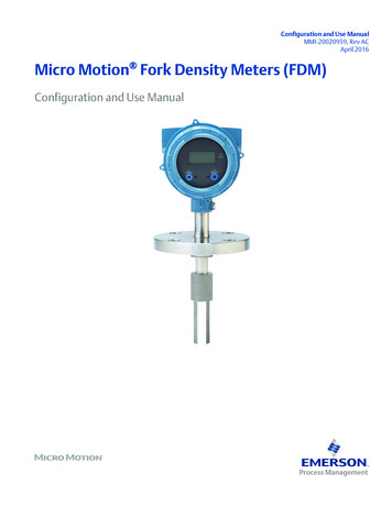
Configuration and Use ManualMMI-20020959, Rev ACApril 2016Micro Motion Fork Density Meters (FDM)Configuration and Use Manual
Safety messagesSafety messages are provided throughout this manual to protect personnel and equipment. Read each safety message carefullybefore proceeding to the next step.Emerson Flow customer serviceEmail: Worldwide: flow.support@emerson.com Asia-Pacific: APflow.support@emerson.comTelephone:North and South AmericaEurope and Middle EastAsia PacificUnited States800-522-6277U.K.0870 240 1978Australia800 158 727Canada 1 303-527-5200The Netherlands 31 (0) 704 136 666New Zealand099 128 804Mexico 41 (0) 41 7686 111France0800 917 901India800 440 1468Argentina 54 11 4837 7000Germany0800 182 5347Pakistan888 550 2682Brazil 55 15 3413 8000Italy8008 77334China 86 21 2892 9000Venezuela 58 26 1731 3446Central & Eastern 41 (0) 41 7686 111Japan 81 3 5769 6803Russia/CIS 7 495 981 9811South Korea 82 2 3438 4600Egypt0800 000 0015Singapore 65 6 777 8211Oman800 70101Thailand001 800 441 6426Qatar431 0044Malaysia800 814 008Kuwait663 299 01South Africa800 991 390Saudi Arabia800 844 9564UAE800 0444 0684
ContentsContentsPart IGetting StartedChapter 1Before you begin .31.11.21.31.4Chapter 2About this manual . 3Model codes and device types . 3Communications tools and protocols . 4Additional documentation and resources . 5Quick start . 72.12.22.3Power up the transmitter .7Check meter status .7Make a startup connection to the transmitter .8Part II Configuration and commissioningChapter 3Introduction to configuration and commissioning . 133.13.23.33.43.5Chapter 4Default values .133.1.1FDM default values . 13Enable access to the off-line menu of the display . 14Disable HART security .15Set the HART lock . 17Restore the factory configuration . 17Configure process measurement .194.14.24.34.44.54.6Verify the calibration factors .194.1.1Calibration factors . 20Configure line density measurement . 204.2.1Configure Density Measurement Unit .204.2.2Configure Density Damping . 224.2.3Configure Density Cutoff . 234.2.4Configure two-phase flow parameters . 24Configure temperature measurement .254.3.1Configure Temperature Measurement Unit . 254.3.2Configure Temperature Damping . 264.3.3Configure Temperature Input . 27Configure the pressure input . 304.4.1Configure the pressure input using ProLink III . 304.4.2Configure the pressure input using the Field Communicator .324.4.3Options for Pressure Measurement Unit . 33Set up the API referral application .344.5.1Set up the API referral application using ProLink III . 344.5.2Set up the API referral application using the Field Communicator . 40Set up concentration measurement . 474.6.1Preparing to set up concentration measurement . 474.6.2Set up concentration measurement using ProLink III .48Configuration and Use Manuali
Contents4.7Chapter 5Configure device options and preferences .675.15.25.35.45.5Chapter 6Configure the transmitter display . 675.1.1Configure the language used for the display . 675.1.2Configure the process variables and diagnostic variables shown on the display .685.1.3Configure the number of decimal places (precision) shown on the display .685.1.4Configure the refresh rate of data shown on the display .695.1.5Enable or disable automatic scrolling through the display variables . 69Enable or disable the Acknowledge All Alerts display command .70Configure security for the display menus . 71Configure alert handling .725.4.1Configure Fault Timeout .725.4.2Configure Alert Severity . 73Configure informational parameters . 75Integrate the meter with the control system . 776.16.26.36.46.56.66.7Chapter 74.6.3Set up concentration measurement using the Field Communicator .554.6.4Using equations to calculate specific gravity, Baumé, Brix, Plato, and Twaddell . 604.6.5Matrix switching . 614.6.6Measuring Net Mass Flow Rate and Net Volume Flow Rate .63Set up flow rate measurement .634.7.1Set up flow rate measurement using ProLink III . 634.7.2Set up flow rate measurement using the Field Communicator . 65Configure Channel B .77Configure the mA output . 786.2.1Configure mA Output Process Variable . 786.2.2Configure Lower Range Value (LRV) and Upper Range Value (URV) .806.2.3Configure Added Damping . 816.2.4Configure mA Output Fault Action and mA Output Fault Level .82Configure the discrete output . 846.3.1Configure Discrete Output Source .846.3.2Configure Discrete Output Polarity . 856.3.3Configure Discrete Output Fault Action . 86Configure an enhanced event .87Configure HART/Bell 202 communications . 886.5.1Configure basic HART parameters .886.5.2Configure HART variables (PV, SV, TV, QV) .896.5.3Configure burst communications . 91Configure Modbus communications .95Configure Digital Communications Fault Action . 976.7.1Options for Digital Communications Fault Action .97Complete the configuration . 997.17.27.3Test or tune the system using sensor simulation .99Back up transmitter configuration . 99Enable HART security .100Part III Operations, maintenance, and troubleshootingChapter 8Transmitter operation .1058.18.2iiRecord the process variables . 105View process variables and diagnostic variables . 105Micro Motion Fork Density Meters (FDM)
Contents8.3Chapter 9Measurement support . 1139.19.29.39.49.59.69.79.8Chapter 108.2.1View process variables using the display . 1058.2.2View process variables and other data using ProLink III . 1068.2.3View process variables using the Field Communicator . 106View and acknowledge status alerts . 1078.3.1View and acknowledge alerts using the display . 1078.3.2View and acknowledge alerts using ProLink III .1098.3.3View alerts using the Field Communicator . 1108.3.4Alert data in transmitter memory . 110Perform the inline calibration check procedure . 1139.1.1Perform the inline calibration check using ProLink III .1149.1.2Perform the inline calibration check using the Field Communicator . 115Perform the Known Density Verification procedure . 1159.2.1Perform the Known Density Verification procedure using the display . 1169.2.2Perform the Known Density Verification procedure using ProLink III . 1179.2.3Perform the Known Density Verification procedure using theField Communicator . 117Adjust density measurement with Density Offset or Density Meter Factor . 118Perform density offset calibration .1199.4.1Perform density offset calibration using the display . 1209.4.2Perform density offset calibration using ProLink III . 1219.4.3Perform density offset calibration using the Field Communicator . 121Perform temperature calibration .1229.5.1Perform temperature calibration using the display . 1229.5.2Perform temperature calibration using ProLink III . 1239.5.3Perform temperature calibration using the Field Communicator .123Adjust concentration measurement with Trim Offset .124Adjust concentration measurement with Trim Slope and Trim Offset . 125Set up user-defined calculations . 1279.8.1Equations used in user-defined calculations . 1299.8.2Measurement units used in user-defined calculations . 129Troubleshooting . 0.1210.1310.1410.15Quick guide to troubleshooting .131Check power supply wiring .132Check grounding .133Perform loop tests . 13310.4.1 Perform loop tests using the display . 13410.4.2 Perform loop tests using ProLink III . 13510.4.3 Perform loop tests using the Field Communicator . 136Status LED states . 137Status alerts, causes, and recommendations . 138Density measurement problems . 143Temperature measurement problems .144API referral problems .145Concentration measurement problems .145Milliamp output problems . 146Discrete output problems .148Time Period Signal (TPS) output problems .148Using sensor simulation for troubleshooting . 149Trim mA outputs . 149Configuration and Use Manualiii
.2410.15.1 Trim mA outputs using ProLink III .14910.15.2 Trim mA outputs using the Field Communicator .150Check HART communications . 151Check Lower Range Value and Upper Range Value . 152Check mA Output Fault Action . 153Check for radio frequency interference (RFI) .153Check the cutoffs . 153Check for two-phase flow (slug flow) . 154Check the drive gain . 15410.22.1 Collect drive gain data . 155Check for internal electrical problems . 155Locate a device using the HART 7 Squawk feature . 156Appendices and referenceAppendix ACalibration certificate . 157A.1Appendix BUsing the transmitter display . 159B.1B.2B.3B.4B.5Appendix CBasic information about the Field Communicator .191Connect with the Field Communicator . 192Concentration measurement matrices, derived variables, and process variables . 195E.1E.2E.3ivBasic information about ProLink III .177Connect with ProLink III . 178C.2.1Connection types supported by ProLink III . 178C.2.2Connect with ProLink III over Modbus/RS-485 .179C.2.3Connect with ProLink III over HART/Bell 202 . 182Using the Field Communicator with the transmitter .191D.1D.2Appendix EComponents of the transmitter interface . 159Use the optical switches . 159Access and use the display menu system . 160B.3.1Enter a floating-point value using the display . 161Display codes for process variables . 164Codes and abbreviations used in display menus . 164Using ProLink III with the transmitter .177C.1C.2Appendix DSample calibration certificate . 157Standard matrices for the concentration measurement application . 195Concentration measurement matrices available by order .196Derived variables and calculated process variables . 198Micro Motion Fork Density Meters (FDM)
Getting StartedPart IGetting StartedChapters covered in this part: Before you beginQuick startConfiguration and Use Manual1
Getting Started2Micro Motion Fork Density Meters (FDM)
Before you begin1Before you beginTopics covered in this chapter: 1.1About this manualModel codes and device typesCommunications tools and protocolsAdditional documentation and resourcesAbout this manualThis manual provides information to help you configure, commission, use, maintain, andtroubleshoot the Micro Motion Fork Density Meter (FDM).The following versions of the FDM are documented in this manual: Fork Density Meter with Analog Outputs Fork Density Meter with Analog Output and Discrete Output Fork Density Meter with Time Period Signal OutputFor the Fork Density Meter with FOUNDATION Fieldbus, see Micro Motion Fork DensityMeters with FOUNDATION Fieldbus: Configuration and Use Manual.ImportantThis manual assumes that the following conditions apply:1.2 The meter has been installed correctly and completely, according to the instructions in theinstallation manual. The installation complies with all applicable safety requirements. The user is trained in all government and corporate safety standards.Model codes and device typesYour device can be identified by the model code on the device tag.Table 1-1: Model codes and device typesElectronics mountingModel codeDevice nicknameI/OFDM*****CFDM mA Two mA outputs RS-485 terminalsIntegralFDM*****DFDM DO One mA output One discrete output RS-485 terminalsIntegralConfiguration and Use Manual3
Before you beginTable 1-1: Model codes and device types (continued)Electronics mountingModel codeDevice nicknameI/OFDM*****BFDM TPS One mA output One Time Period Signal outputFDM*****AFDM FF FOUNDATION fieldbus Integral4-wire remotetransmitterRestrictionThe FDM and FDM FF support a complete set of application and configuration options. The FDM DOand FDM TPS support a subset of configuration options. Refer to the product data sheet for details.1.3Communications tools and protocolsYou can use several different communications tools and protocols to interface with thedevice. You may use different tools in different locations or for different tasks.Table 1-2: Communications tools, protocols, and related informationCommunications toolSupported protocolsScopeIn this manualDisplayNot applicableBasic configuration andcommissioningComplete user informa- Not applicabletion. See Appendix B.ProLink III Modbus/RS-485 HART/Bell 202 Service portComplete configuration Basic user information.and commissioningSee Appendix C.User manual Installed with software On Micro Motionuser documentationCD On Micro Motionweb site(www.micromo‐tion.com)Field Communicator HART/Bell 202Complete configuration Basic user information.and commissioningSee Appendix D.User manual onMicro Motion web site(www.micromo‐tion.com )For more informationTipYou may be able to use other communications tools from Emerson Process Management, such asAMS Suite: Intelligent Device Manager, or the Smart Wireless THUM Adapter. Use of AMS or theSmart Wireless THUM Adapter is not discussed in this manual. For more information on the SmartWireless THUM Adapter, refer to the documentation available at www.micromotion.com.4Micro Motion Fork Density Meters (FDM)
Before you begin1.4Additional documentation and resourcesMicro Motion provides additional documentation to support the installation and operationof the device.Table 1-3: Additional documentation and resourcesTopicDocumentDevice installationMicro Motion Fork Density Meters (FDM): Installation ManualProduct data sheetMicro Motion Fork Density Meters: Product Data SheetAll documentation resources are available on the Micro Motion web site atwww.micromotion.com or on the Micro Motion user documentation DVD.Configuration and Use Manual5
Before you begin6Micro Motion Fork Density Meters (FDM)
Quick start2Quick startTopics covered in this chapter: 2.1Power up the transmitterCheck meter statusMake a startup connection to the transmitterPower up the transmitterThe transmitter must be powered up for all configuration and commissioning tasks, or forprocess measurement.1.Ensure that all transmitter and sensor covers and seals are closed.WARNING!To prevent ignition of flammable or combustible atmospheres, ensure that all coversand seals are tightly closed. For hazardous area installations, applying power whilehousing covers are removed or loose can cause an explosion.2.Turn on the electrical power at the power supply.The transmitter will automatically perform diagnostic routines. During this period,Alert 009 is active. The diagnostic routines should complete in approximately30 seconds.PostrequisitesAlthough the sensor is ready to receive process fluid shortly after power-up, the electronicscan take up to 10 minutes to reach thermal equilibrium. Therefore, if this is the initialstartup, or if power has been off long enough to allow components to reach ambienttemperature, allow the electronics to warm up for approximately 10 minutes beforerelying on process measurements. During this warm-up period, you may observe minormeasurement instability or inaccuracy.2.2Check meter statusCheck the meter for any error conditions that require user action or that affectmeasurement accuracy.1.Wait approximately 10 seconds for the power-up sequence to complete.Immediately after power-up, the transmitter runs through diagnostic routines andchecks for error conditions. During the power-up sequence, Alert A009 is active.This alert should clear automatically when the power-up sequence is complete.2.Check the status LED on the transmitter.Configuration and Use Manual7
Quick startTable 2-1: Transmitter status reported by status LEDLED stateDescriptionRecommendationGreenNo alerts are active.Continue with configuration or process measurement.YellowOne or more low-severity alerts are active.A low-severity alert condition does not affectmeasurement accuracy or output behavior.You can continue with configuration or process measurement. If you choose, you can identify and resolve the alert condition.Flashing yellowCalibration in progress, or Known Density Veri- The measurement can fluctuate during thefication in progress.calibration process or change as a result of thecalibration process. The alert will clear whenthe calibration is complete. Check the calibration results before continuing.RedOne or more high-severity alerts are active. 2.3A high-severity alert condition affects measurement accuracy and output behavior. Resolve the alert condition before continuing.View and acknowledge status alerts (Section 8.3)Status alerts, causes, and recommendations (Section 10.6)Make a startup connection to the transmitterFor all configuration tools except the display, you must have an active connection to thetransmitter to configure the transmitter.Identify the connection type to use, and follow the instructions for that connection type inthe appropriate appendix. Use the default communications parameters shown in theappendix.Communications toolConnection type to useInstructionsProLink IIIModbus/RS-485Appendix CHART/Bell 202Field CommunicatorHART/Bell 202Appendix DPostrequisites(Optional) Change the communications parameters to site-specific values.8 To change the communications parameters using ProLink III, choose Device Tools Configuration Communications. To change the communications parameters using the Field Communicator, chooseConfigure Manual Setup HART Communications.Micro Motion Fork Density Meters (FDM)
Quick startImportantIf you are changing communications parameters for the connection type that you are using, you willlose the connection when you write the parameters to the transmitter. Reconnect using the newparameters.Con
Emerson Flow customer service Email: Worldwide: flow.support@emerson.com Asia-Pacific: APflow.support@emerson.com Telephone: North and South America Europe and Middle East Asia Pacific United States 800-522-6277 U.K. 0870 240 1978 Australia 800 158 727 Canada 1 303-527-5200 The Netherlands 31 (0) 704 136 666 New Zealand 099 128 804