Transcription
SuperBlade 4U EnclosuresUSER’S MANUALRevision 2.0b
The information in this User’s Manual has been carefully reviewed and is believed to be accurate. The vendor assumesno responsibility for any inaccuracies that may be contained in this document, and makes no commitment to updateor to keep current the information in this manual, or to notify any person or organization of the updates. Please Note:For the most up-to-date version of this manual, please see our website at www.supermicro.com.Super Micro Computer, Inc. ("Supermicro") reserves the right to make changes to the product described in this manualat any time and without notice. This product, including software and documentation, is the property of Supermicro and/or its licensors, and is supplied only under a license. Any use or reproduction of this product is not allowed, exceptas expressly permitted by the terms of said license.IN NO EVENT WILL Super Micro Computer, Inc. BE LIABLE FOR DIRECT, INDIRECT, SPECIAL, INCIDENTAL,SPECULATIVE OR CONSEQUENTIAL DAMAGES ARISING FROM THE USE OR INABILITY TO USE THIS PRODUCTOR DOCUMENTATION, EVEN IF ADVISED OF THE POSSIBILITY OF SUCH DAMAGES. IN PARTICULAR, SUPERMICRO COMPUTER, INC. SHALL NOT HAVE LIABILITY FOR ANY HARDWARE, SOFTWARE, OR DATA STOREDOR USED WITH THE PRODUCT, INCLUDING THE COSTS OF REPAIRING, REPLACING, INTEGRATING,INSTALLING OR RECOVERING SUCH HARDWARE, SOFTWARE, OR DATA.Any disputes arising between manufacturer and customer shall be governed by the laws of Santa Clara County in theState of California, USA. The State of California, County of Santa Clara shall be the exclusive venue for the resolutionof any such disputes. Supermicro's total liability for all claims will not exceed the price paid for the hardware product.FCC Statement: This equipment has been tested and found to comply with the limits for a Class A or Class B digitaldevice pursuant to Part 15 of the FCC Rules. These limits are designed to provide reasonable protection againstharmful interference when the equipment is operated in industrial environment for Class A device or in residentialenvironment for Class B device. This equipment generates, uses, and can radiate radio frequency energy and, if notinstalled and used in accordance with the manufacturer’s instruction manual, may cause harmful interference withradio communications. Operation of this equipment in a residential area is likely to cause harmful interference, inwhich case you will be required to correct the interference at your own expense.California Best Management Practices Regulations for Perchlorate Materials: This Perchlorate warning applies onlyto products containing CR (Manganese Dioxide) Lithium coin cells. “Perchlorate Material-special handling may apply.See NING: This product can expose you to chemicals includinglead, known to the State of California to cause cancer and birthdefects or other reproductive harm. For more information, goto www.P65Warnings.ca.gov.The products sold by Supermicro are not intended for and will not be used in life support systems, medical equipment,nuclear facilities or systems, aircraft, aircraft devices, aircraft/emergency communication devices or other criticalsystems whose failure to perform be reasonably expected to result in significant injury or loss of life or catastrophicproperty damage. Accordingly, Supermicro disclaims any and all liability, and should buyer use or sell such productsfor use in such ultra-hazardous applications, it does so entirely at its own risk. Furthermore, buyer agrees to fullyindemnify, defend and hold Supermicro harmless for and against any and all claims, demands, actions, litigation, andproceedings of any kind arising out of or related to such ultra-hazardous use or sale.Manual Revision 2.0bRelease Date: April 22, 2022mkUnless you request and receive written permission from Super Micro Computer, Inc., you may not copy any part of thisdocument. Information in this document is subject to change without notice. Other products and companies referredto herein are trademarks or registered trademarks of their respective companies or mark holders.Copyright 2022 by Super Micro Computer, Inc.All rights reserved.Printed in the United States of America
PrefacePrefaceAbout this ManualThis manual is written for professional system integrators and PC technicians. It providesinformation for the installation and use of the enclosure. Installation and maintenance shouldbe performed by experienced technicians only.Please refer to the specifications page on our website for updates on supported memory,processors and operating systems (www.supermicro.com).NotesFor your system to work properly, please follow the links below to download all necessarydrivers/utilities and the user’s manual for your server. Supermicro product manuals: www.supermicro.com/support/manuals/ Product safety info: www.supermicro.com/about/policies/safety information.cfmIf you have any questions, please contact our support team at:support@supermicro.comThis manual may be periodically updated without notice. Please check the Supermicro websitefor possible updates to the manual revision level.WarningsSpecial attention should be given to the following symbols used in this manual.Warning! Indicates important information given to prevent equipment/property damageor personal injury.Warning! Indicates high voltage may be encountered when performing a procedure.3
PrefaceContentsChapter 1 Introduction1.1 Overview.7Design Features.71.2 Models and Features.8Models.8Front View.9Rear View.101.3 Switches.11Switches Supported in each Enclosure Model.12Chapter 2 Installation into a Rack2.1 Overview.132.2 Unpacking the System.132.3 Preparing for Setup.13Choosing a Setup Location.13Rack Precautions.14Rack Mounting Considerations.14Ambient Operating Temperature.14Airflow.14Mechanical Loading.14Circuit Overloading.15Reliable Ground.152.4 Installing the Enclosure.16Chapter 3 Maintenance and Component Installation3.1 Removing Power .183.2 Installing Components.19Installing a Blade Unit into the Enclosure.203.3 Software Mode Selection.213.4 Quick Start Setup.21Chapter 4 Power and Cooling4.1 Module Description.22Power Cord.224.2 Installing a Power Supply.23Removing a Power Supply.244
Preface4.3 Power Supply Failure.24Redundant Power Supplies.244.4 Power Management.254.5 Cooling.25Auxiliary Fans.254.6 Power Supply Specifications.27Chapter 5 Chassis Management Module5.1 Features.29Capabilities.31Module Redundancy.31Determining Master/Slave Modules Status.315.2 Installation.315.3 Configuring the CMM.32Configuring the CMM in Windows OS: .335.4 CMM Functions.35Remote KVM over IP.35Remote Storage (Virtual Media).35Serial Over LAN (SOL).35Monitoring Functions.36Power Consumption Management.365.5 Reset Button.365.6 USB Ports.375.7 Firmware.375.8 Web-based Management Utility.37Supported Browsers.37Network Connection/Login.38Address Defaults.38Home Page.38Chapter 6 Data Plane6.1 414J Enclosure.396.2 414E Enclosure.41Appendix A Standardized Warning Statements for AC SystemsAppendix B System Specifications5
Contacting SupermicroContacting SupermicroHeadquartersAddress:Super Micro Computer, Inc.980 Rock Ave.San Jose, CA 95131 U.S.A.Tel: 1 (408) 503-8000Fax: 1 (408) 503-8008Email:marketing@supermicro.com (General Information)support@supermicro.com (Technical per Micro Computer B.V.Het Sterrenbeeld 28, 5215 ML's-Hertogenbosch, The NetherlandsTel: 31 (0) 73-6400390Fax: 31 (0) 73-6416525Email:sales@supermicro.nl (General Information)support@supermicro.nl (Technical Support)rma@supermicro.nl (Customer ss:Super Micro Computer, Inc.3F, No. 150, Jian 1st Rd.Zhonghe Dist., New Taipei City 235Taiwan (R.O.C)Tel: 886-(2) 8226-3990Fax: 886-(2) w.supermicro.com.tw6
Chapter 1: IntroductionChapter 1Introduction1.1 OverviewThe Supermicro SuperBlade 4U Enclosures provide power, cooling, management and networkfunctions for multiple blade servers. They can house up to 14 one or two socket blades.In this manual, “blade” or “blade unit” refers to a single blade server. “Blade system” refersto the enclosure, blades units, and various management and networking modules. "Modules"refer to management, switch, network, or other specialized components.Design FeaturesRemote Management – The Chassis Management Module (CMM) manages the enclosureand individual blades. Chapter 5 and a separate CMM manual provide instruction.Efficient Power – Power supply modules are designed to operate up to 96% efficiency tolimit energy consumption and heat.Operating Systems – Microsoft Windows, VM Ware and Linux operating systems aresupported by the SuperBlade servers. Different operating systems can run on different bladeswithin the same enclosure.Status Indicators – Two LEDs on the front of the enclosure provide power status and faultstatus.Safety ModelsThe following safety models associated with the SuperBlade 4U enclosure have been certifiedas compliant with UL or CSA: B414-22.7
Chapter 1: Introduction1.2 Models and FeaturesThe enclosure houses up to 14 SuperBlade servers with one or two sockets. The maximummay vary depending on the CPU wattages. The enclosure also requires one CMM.Models4U Enclosure CapabilitiesModelPower SuppliesSwitch OptionsSBE-414J-422Four 2200WTwo Ethernet switches with 1G/10G/25Gspeed supportSBE-414E-422Four 2200WSBE-414E-222Two 2200W(plus two fans)SBE-414E-220DFour 2000W DCTwo Ethernet switches with 1G/10G speedsupport8
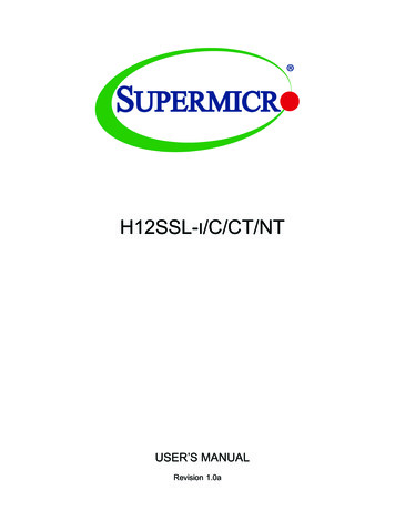
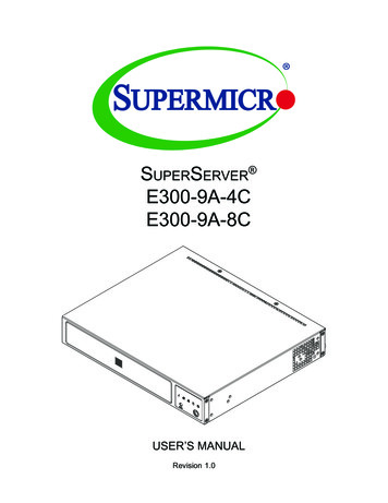
Chapter 1: IntroductionFront ViewStatusIndicatorsLAN PortConsole PortFigure 1-1. SBE-414E Front ViewFront FeaturesFeatureDescriptionStatusIndicatorsGreen: All blades, switch modules, CMM, power supplies, and fans are operating normally.Red: Critical warning—some components or modules are not operating normally.LAN PortManagement of network port for the blade systemConsole PortSerial console port for the CMM9
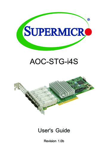
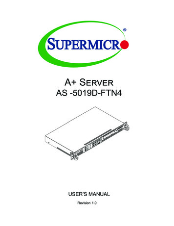
Chapter 1: IntroductionRear View1111PA1PA2PA3PA4342422Figure 1-2. SBE-414E-422 Rear ViewRear FeaturesFeatureDescription1Four power supply modules with fans; for models with only two power supply modules, the outsidetwo positions are filled with non-power supply fans2Nine auxiliary fans in three modules3Chassis Management Module (CMM)4Two switch modules10
Chapter 1: Introduction1.3 SwitchesSeveral switch module and pass-thru module options facilitate networking.Switch ModulesModelDescriptionSBM-25G-100Marvell BobCat3 98CX8410 25GbE Low Latency Switch20x 25G Ethernet downlink (backward compatible to 20x10G), 4x 100G/40G Ethernetuplinks, each can split into 4x 25G or 4x 10G uplinks with optional fan-out cables1x Gigabit Ethernet uplinkone console portMBM-GEM-001*Intel FM5224 GbE Low Latency Switch56x 2.5Gbps internal ports,1Gbps RJ45, 2x 40Gbps QSFP or 8x 10Gbps SFP uplinksone USB port, one Console portMBM-GEM-004Broadcom Switch40x 1Gbps internal ports; 4x 10Gbps (SFP ) and 8x 1Gbps (RJ45) External Uplink PortsVLAN, STP, 802.1AX, 02.1AB10GbE, one console portMBM-XEM-001*Intel FM6348 10GbE Low Latency Switch4x 40Gbps QSFP uplinks, 56x 10Gbps or 1Gbps downlinks, one console port, one USB portMBM-XEM-002Broadcom Low Latency Switch56x 10Gbps Internal Ports; 2x 40Gbps (QSFP ) and 4x 10 Gbps (SFP ) External UplinkPorts VLAN, STP, 802.1AX, 802.1AB, one console port, one USB portMBM-XEM-002 Broadcom Low Latency Switch56x 10Gbps Internal Ports; 2x 40Gbps (QSFP ) and 4x 10 Gbps (SFP ) External UplinkPorts VLAN, STP, 802.1AX, 802.1AB, one console port, one USB portMBM-XEM-100Marvel BobCat3 Low Latency Switch56x 10Gbps Internal Ports; 4x 100Gbps/40Gbps (QSFP28) and 1x 1Gbps (RJ45) ExternalUplink Ports VLAN, STP, 802.1AX, 802.1AB, one console portSBM-25G-P10Supermicro Pass-thru Switch20x 25G/10G Ethernet downlinks, 5x 100G Ethernet uplinks (each can split into 4x 25G or4x 10G uplinks with optional fan-out cables) or 5x 40G Ethernet uplinks (each can split into4x 10G uplinks with optional fan-out cables)1 Console port*EOLSee also the SuperBlade Switch Support Matrix.These modules are further described in a separate manual.11
Chapter 1: IntroductionSwitches Supported in each Enclosure ModelSwitch Modules per EnclosureSwitch Module414E414J25G EthernetSBM-25G-100na21G EthernetMBM-GEM-001*221G EthernetMBM-GEM-0042210G EthernetMBM-XEM-001*2210G EthernetMBM-XEM-0022210G EthernetMBM-XEM-002 2210G EthernetMBM-XEM-1002225G Path-ThruSBM-25G-P1022*EOL12
Chapter 2: Installation into a RackChapter 2Installation into a Rack2.1 OverviewThis chapter provides advice and instructions for mounting your system in a server rack.2.2 Unpacking the SystemInspect the box in which the enclosure was shipped, and note if it was damaged. If so, filea claim with the carrier.Decide on a suitable location for the rack unit that will hold the server. It should be situatedin a clean, dust-free area that is well ventilated. Avoid areas where heat, electrical noise andelectromagnetic fields are generated. It will also require a grounded AC power outlet nearby.Be sure to read the precautions and considerations noted in Appendix A.2.3 Preparing for SetupThe box in which the system was shipped should include the rackmount hardware needed toinstall it into the rack. Please read this section in its entirety before you begin the installation.Choosing a Setup Location The system should be situated in a clean, dust-free area that is well ventilated. Avoid areaswhere heat, electrical noise and electromagnetic fields are generated. Leave enough clearance in front of the rack so that you can open the front door completely( 25 inches) and approximately 30 inches of clearance in the back of the rack to allowsufficient space for airflow and access when servicing. This product should be installed only in a Restricted Access Location (dedicated equipmentrooms, service closets, etc.). This product is not suitable for use with visual display workplace devices according to §2of the German Ordinance for Work with Visual Display Units.13
Chapter 2: Installation into a RackRack Precautions Ensure that the leveling jacks on the bottom of the rack are extended to the floor so thatthe full weight of the rack rests on them. In single rack installations, stabilizers should be attached to the rack. In multiple rack installations, the racks should be coupled together. Always make sure the rack is stable before extending a server or other component fromthe rack. You should extend only one server or component at a time. Extending two or more simultaneously may cause the rack to become unstable. Review the electrical and general safety precautions in Appendix A. Determine the placement of each component in the rack before you install the rails. Install the heaviest server components at the bottom of the rack first and then work yourway up. Use a regulating uninterruptible power supply (UPS) to protect the server from powersurges and voltage spikes and to keep your system operating in case of a power failure. Allow power supply modules to cool before touching them. When not servicing, always keep the front door of the rack and all covers/panels on theservers closed to maintain proper cooling.Rack Mounting ConsiderationsAmbient Operating TemperatureIf installed in a closed or multi-unit rack assembly, the ambient operating temperature ofthe rack environment may be greater than the room's ambient temperature. Therefore,consideration should be given to installing the equipment in an environment compatible withthe manufacturer’s maximum rated ambient temperature (TMRA).AirflowEquipment should be mounted into a rack so that the amount of airflow required for safeoperation is not compromised.Mechanical LoadingEquipment should be mounted into a rack so that a hazardous condition does not arise dueto uneven mechanical loading.14
Chapter 2: Installation into a RackCircuit OverloadingConsideration should be given to the connection of the equipment to the power supply circuitryand the effect that any possible overloading of circuits might have on overcurrent protectionand power supply wiring. Appropriate consideration of equipment nameplate ratings shouldbe used when addressing this concern.Reliable GroundA reliable ground must be maintained at all times. To ensure this, the rack itself should begrounded. Particular attention should be given to power supply connections other than thedirect connections to the branch circuit (i.e. the use of power strips, etc.).Warning! To prevent bodily injury when mounting or servicing this unit in a rack, youmust take special precautions to ensure that the system remains stable. The followingguidelines are provided to ensure your safety: This unit should be mounted at the bottom of the rack if it is the only unit in the rack. When mounting this unit in a partially filled rack, load the rack from the bottom to the topwith the heaviest component at the bottom of the rack. If the rack is provided with stabilizing devices, install the stabilizers before mounting orservicing the unit in the rack. Slide rail mounted equipment is not to be used as a shelf or a work space.15
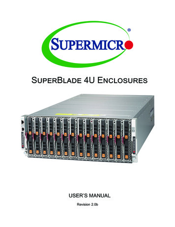
Chapter 2: Installation into a Rack2.4 Installing the EnclosureThere are a variety of rack units on the market, which may require a slightly different assemblyprocedure. Also see the instructions that came with the rails. This rail set fits a rack between28.5 and 33.7 inch depth.1Figure 2-1. Rack Rails(Left Rail Assembly Shown)When installing the enclosure, remove all blades, power supplies, switches and managementmodules. Install these modules after the enclosure is mounted.If desired, use the template to mark the position that the enclosure will occupy on the rack.The chassis comes with two sets of rack rails, one set for the right side of the chassis andone for the left.1. For each rail, sections are screwed together to keep them immobile during shipping.Release these screws just enough to allow the rails to slide apart.2. Slide the rails apart far enough to match the depth of the rack. Note the arrow on therail, which indicates the end that attaches to the front of the rack. Position each rail andsecure the front to the front post of the rack with two flathead screws. Then secure theback of each rail to the rear of the rack with two flathead screws .16
Chapter 2: Installation into a RackFigure 2-2. Securing the Left Rail to the Rack3. Lift the enclosure and slide it into the rack. Use two roundhead screws on each side ofthe server to lock it into place.Figure 2-4. Enclosure InstalledNote: The figure above is for illustrative purposes only. Always install enclosures at the bottomof the rack first.Stability hazard. The rack stabilizing mechanism must be in place, or the rack must bebolted to the floor before you slide the unit out for servicing. Failure to stabilize the rackcan cause the rack to tip over.SCALE171:2
Chapter 3: Maintenance and Component InstallationChapter 3Maintenance and Component InstallationThis chapter provides instructions on installing and replacing main system components. Toprevent compatibility issues, only use components that match the specifications and/or partnumbers given.3.1 Removing PowerUse the following procedure to ensure that power has been removed from the system. Thisstep is necessary when removing or installing non-hot-swap components, such as the onlyCMM in an enclosure.1. Use the operating systems to power down all blades.2. Disconnect all the power cords from the power strip or outlet.3. Disconnect the power cords from the power supply modules.18
Chapter 3: Maintenance and Component Installation3.2 Installing ComponentsInstall: Power Supply Modules (details in Chapter 4)FansCMMSwitches or pass-thru modulesBlade serversIn all cases, slide the component into the enclosure, then secure with the locking lever.Note: All module bays must be populated either with a module or a dummy module cover tomaintain proper airflow.Locking LeverFigure 3-1. Installling a Switch19
Chapter 3: Maintenance and Component InstallationInstalling a Blade Unit into the EnclosureSee the manual for your SuperBlade server for full details on its installation and configuration.1. Fully open the locking lever on the blade and slowly push it into its bay.2. When the blade is seated in the bay, push the locking lever into its locked position,making sure the notches in both handles catch the lip of the enclosure.Blades can be hot-plugged into the enclosure.Use caution when inserting a blade into the enclosure, and do not damage the powerconnector.Locking LeversFigure 3-1. Installling a Blade into the Enclosure20
Chapter 3: Maintenance and Component Installation3.3 Software Mode SelectionUsing the Web-based Management Utility, you can specify your SuperBlade system to use adifferent mode for quieter operation and lower fan speed. This is done by selecting a modein the CMM Operation Mode section of the CMM Status screen. This screen allows you tospecify your system to run in either Office Blade Mode (for quieter operation) or EnterpriseMode (for normal operation). See the CMM manual for more details.3.4 Quick Start SetupThis section is a brief description of how to get your SuperBlade system up and running.1. Unpack the components of your SuperBlade system and check the packing list fordamaged or missing components.2. Mount the enclosure in your server rack. (Chapter 2)3. Install the power supply modules into the rear of the enclosure. (Chapter 4).4. Install the CMM module (Chapter 5) and any other modules into the rear of theenclosure.5. Install networking modules, such as switches.6. Prepare each blade server with memory, storage drives, add-on cards, etc. Install theminto the enclosure. (See Blade User's Manual)7. Connect the power cords for your enclosure power supply and plug them into yourpower source only after you have installed and secured all system components.8. Power up your system. Check all to be sure all components are operating normally.9. Install an operating system for each blade module.21
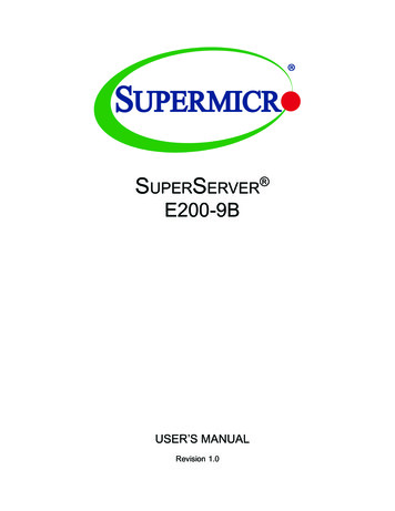
Chapter 4: Power Supplies and FansChapter 4Power and CoolingThe SuperBlade enclosure integrates a power supply and a cooling fan into a single module.The fan can operate independently from the power supply, so that if the power supply fails,the fan continues to provide cooling for the system. The Chassis Management Module (CMM)monitors the status of the power supplies and the power information for the enclosure.Figure 4-1. Example Power and Fan Module, PWS-2K21A-BR4.1 Module DescriptionAn LED status indicator is located near the locking lever.Status IndictorColorDescriptionRedPower module failureAmberPossible module failure or the AC power cord unpluggedGreenModule operating normallyPower CordA plastic locking clip partially covering the socket was designed to prevent the power supplymodule from being removed with the power cord still connected.Only the recommended power cord or an equivalent 14 gauge cord should be used. TypicalC13/C14 cords are only 16 Gauge wiring and pose a fire hazard if substituted.22
Chapter 4: Power Supplies and FansFor details on the required power cord for your country, see the Supermicro web site ply/powercord.cfm4.2 Installing a Power SupplyTo prevent compatibility issues, only use components that match the specifications or partnumbers.1. Insert the power module into the empty power bay. Be sure that the orientation iscorrect. Match the pictures of the chassis front in Chapter 1. If you inadvertently put apower supply upside down, it can be very difficult to remove.If using fan-only modules (non-power) or BBPs, insert them in the two outside slots.2. Push unit
Remote Management - The Chassis Management Module (CMM) manages the enclosure and individual blades. Chapter 5 and a separate CMM manual provide instruction. Efficient Power - Power supply modules are designed to operate up to 96% efficiency to limit energy consumption and heat.