Transcription
A ServerAS -5019D-FTN4USER’S MANUALRevision 1.0
The information in this User’s Manual has been carefully reviewed and is believed to be accurate. The vendor assumesno responsibility for any inaccuracies that may be contained in this document, and makes no commitment to updateor to keep current the information in this manual, or to notify any person or organization of the updates. Please Note:For the most up-to-date version of this manual, please see our website at www.supermicro.com.Super Micro Computer, Inc. ("Supermicro") reserves the right to make changes to the product described in this manualat any time and without notice. This product, including software and documentation, is the property of Supermicro and/or its licensors, and is supplied only under a license. Any use or reproduction of this product is not allowed, exceptas expressly permitted by the terms of said license.IN NO EVENT WILL Super Micro Computer, Inc. BE LIABLE FOR DIRECT, INDIRECT, SPECIAL, INCIDENTAL,SPECULATIVE OR CONSEQUENTIAL DAMAGES ARISING FROM THE USE OR INABILITY TO USE THIS PRODUCTOR DOCUMENTATION, EVEN IF ADVISED OF THE POSSIBILITY OF SUCH DAMAGES. IN PARTICULAR, SUPERMICRO COMPUTER, INC. SHALL NOT HAVE LIABILITY FOR ANY HARDWARE, SOFTWARE, OR DATA STOREDOR USED WITH THE PRODUCT, INCLUDING THE COSTS OF REPAIRING, REPLACING, INTEGRATING,INSTALLING OR RECOVERING SUCH HARDWARE, SOFTWARE, OR DATA.Any disputes arising between manufacturer and customer shall be governed by the laws of Santa Clara County in theState of California, USA. The State of California, County of Santa Clara shall be the exclusive venue for the resolutionof any such disputes. Supermicro's total liability for all claims will not exceed the price paid for the hardware product.FCC Statement: This equipment has been tested and found to comply with the limits for a Class A digital devicepursuant to Part 15 of the FCC Rules. These limits are designed to provide reasonable protection against harmfulinterference when the equipment is operated in a commercial environment. This equipment generates, uses, and canradiate radio frequency energy and, if not installed and used in accordance with the manufacturer’s instruction manual,may cause harmful interference with radio communications. Operation of this equipment in a residential area is likelyto cause harmful interference, in which case you will be required to correct the interference at your own expense.California Best Management Practices Regulations for Perchlorate Materials: This Perchlorate warning applies onlyto products containing CR (Manganese Dioxide) Lithium coin cells. “Perchlorate Material-special handling may apply.See NING: This product can expose you to chemicals includinglead, known to the State of California to cause cancer and birthdefects or other reproductive harm. For more information, goto www.P65Warnings.ca.gov.The products sold by Supermicro are not intended for and will not be used in life support systems, medical equipment,nuclear facilities or systems, aircraft, aircraft devices, aircraft/emergency communication devices or other criticalsystems whose failure to perform be reasonably expected to result in significant injury or loss of life or catastrophicproperty damage. Accordingly, Supermicro disclaims any and all liability, and should buyer use or sell such productsfor use in such ultra-hazardous applications, it does so entirely at its own risk. Furthermore, buyer agrees to fullyindemnify, defend and hold Supermicro harmless for and against any and all claims, demands, actions, litigation, andproceedings of any kind arising out of or related to such ultra-hazardous use or sale.Manual Revision 1.0Release Date: March 25, 2019Unless you request and receive written permission from Super Micro Computer, Inc., you may not copy any part of thisdocument. Information in this document is subject to change without notice. Other products and companies referredto herein are trademarks or registered trademarks of their respective companies or mark holders.Copyright 2019 by Super Micro Computer, Inc.All rights reserved.Printed in the United States of America
PrefacePrefaceAbout this ManualThis manual is written for professional system integrators and PC technicians. It providesinformation for the installation and use of this server. Installation and maintenance should beperformed by experienced technicians only.Please refer to the AS -5019D-FTN4 server specifications page on our website for updateson supported memory, processors and operating systems (http://www.supermicro.com).NotesFor your system to work properly, please follow the links below to download all necessarydrivers/utilities and the user’s manual for your server. Supermicro product manuals: http://www.supermicro.com/support/manuals/ Product drivers and utilities: https://www.supermicro.com/wftp Product safety info: http://www.supermicro.com/about/policies/safety information.cfmIf you have any questions, please contact our support team at:support@supermicro.comThis manual may be periodically updated without notice. Please check the Supermicro websitefor possible updates to the manual revision level.WarningsSpecial attention should be given to the following symbols used in this manual.Warning! Indicates important information given to prevent equipment/property damageor personal injury.Warning! Indicates high voltage may be encountered when performing a procedure.3
A Server AS -5019D-FTN4 User's ManualContentsChapter 1 Introduction1.1 Overview.81.2 Unpacking the System.81.3 System Features.91.4 Chassis Features.10Control Panel.10Front Features.11Chassis Rear.121.5 Motherboard Layout.13Quick Reference.14Chipset Block Diagram.151.6 Where to Get Replacement Components.161.7 Returning Merchandise for Service.16Chapter 2 Server Installation2.1 Overview.172.2 Preparing for Setup.17Choosing a Setup Location.17Rack Precautions.17Server Precautions.18Rack Mounting Considerations.18Ambient Operating Temperature.18Airflow.18Mechanical Loading.18Circuit Overloading.18Reliable Ground.192.3 Installing the System Into a Rack.20Installing the Server into a Telco Rack.21Chapter 3 Maintenance and Component Installation3.1 Removing Power.223.2 Accessing the System.234
PrefaceMemory.24Memory Support.24General Guidelines for Optimizing Memory Performance.24DIMM Module Population Sequence.25DIMM Installation.26Motherboard Battery.273.4 Chassis Components.28Storage Drives.28PCI Expansion Cards .30System Fans.31Power Supply.33Chapter 4 Motherboard Connections4.1 Power Connections.344.2 Headers and Connectors.35Front Control Panel.384.3 Ports.414.4 Jumpers.42Explanation of Jumpers.424.5 LED Indicators.44Chapter 5 Software5.1 Microsoft Windows OS Installation.465.2 Driver Installation.485.3 SuperDoctor 5.495.4 IPMI.49Chapter 6 BIOS6.1 Introduction.50Starting BIOS Setup Utility.506.2 Main Setup.506.3 Advanced Settings Menu.526.4 Event Logs.746.5 IPMI.756.6 Security Settings.775
A Server AS -5019D-FTN4 User's Manual6.7 Boot Settings.816.8 Save & Exit.84AppendixAppendixAppendixAppendixA BIOS Error CodesB Standardized Warning Statements for AC SystemsC System SpecificationsD UEFI BIOS Recovery6
Contacting SupermicroContacting SupermicroHeadquartersAddress:Super Micro Computer, Inc.980 Rock Ave.San Jose, CA 95131 U.S.A.Tel: 1 (408) 503-8000Fax: 1 (408) 503-8008Email:marketing@supermicro.com (General Information)support@supermicro.com (Technical per Micro Computer B.V.Het Sterrenbeeld 28, 5215 ML's-Hertogenbosch, The NetherlandsTel: 31 (0) 73-6400390Fax: 31 (0) 73-6416525Email:sales@supermicro.nl (General Information)support@supermicro.nl (Technical Support)rma@supermicro.nl (Customer ss:Super Micro Computer, Inc.3F, No. 150, Jian 1st Rd.Zhonghe Dist., New Taipei City 235Taiwan (R.O.C)Tel: 886-(2) 8226-3990Fax: 886-(2) w.supermicro.com.tw7
A Server AS -5019D-FTN4 User's ManualChapter 1Introduction1.1 OverviewThis chapter provides a brief outline of the functions and features of the AS -5019D-FTN4server, based on the M11SDV-8C-LN4F motherboard and the SC505-203B chassis. TheAS -5019D-FTN4 server has input/output ports in the rear and in the front.In addition to the motherboard and chassis, several important parts that are included withthe system are listed below.Main Parts ListDescriptionPart NumberQuantityPower Supply 1Riser CardRSC-RR1U-E1611.2 Unpacking the SystemInspect the box the system was shipped in and note if it was damaged in any way. If anyequipment appears damaged, please file a damage claim with the carrier who delivered it.Decide on a suitable location for the rack unit that will hold the server. It should be situatedin a clean, dust-free area that is well ventilated. Avoid areas where heat, electrical noise andelectromagnetic fields are generated. It will also require a grounded AC power outlet nearby.Be sure to read the precautions and considerations noted in Appendix B.8
Chapter 1: Introduction1.3 System FeaturesThe following table is an overview of the main features of the AS -5019D-FTN4 server.System CPUAMD EPYC 3251 SoCMemoryUp to 512GB of Registered ECC DDR4 wth speeds up to 2666MHz in four DIMMs 4-channel memory bus.ChipsetSystem on ChipExpansion SlotsOne PCI-E 3.0 x16One M.2 M-Key (PCI-E x4 80mm length support NVMe SSD)Storage DrivesFour 2.5" SATA3Two front USB3Power200W AC-DC 80Plus Gold level moduleCoolingTwo 40x28mm 4-pin PWM fanInput/OutputFour SATA3 (6Gbps) portsTwo USB 3.0 ports (front)One VGA port (fron)LAN portsFour RJ45 Gigabit Ethernet LAN ports (front)One RJ45 Dedicated IPMI LAN port (front)Form FactorMini-iTX form factor (6.75" x 6.75") (170mm x 170mm)9
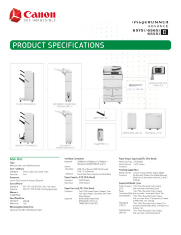
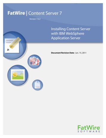
A Server AS -5019D-FTN4 User's Manual1.4 Chassis FeaturesControl PanelPower switches and status LEDs are located on the control panel on the front of the chassis.1234567Figure 1-1. Control PanelControl Panel FeaturesItemFeaturesDescription1Information LEDAlerts operator to several states, as noted in the table below2NIC2 LEDIndicates network activity on LAN port 2 when flashing3NIC1 LEDIndicates network activity on LAN port 1 when flashing4HDD LEDIndicates hard drive activity when flashing5Power LEDIndicates power is being supplied to the system power supply; illuminated whenthe system is operating normally6Reset ButtonReboots the system7Power ButtonApplies or removes power from the power supply to the server; standby power ismaintainedInformation LEDStatusDescriptionContinuously on andredAn overheat condition has occurred.(This may be caused by cable congestion.)Blinking red (1Hz)Fan failure, check for an inoperative fan.Blinking red (0.25Hz)Power failure, check for a non-operational power supply.Solid blueUID has been activated locally to locate the server in a rackenvironment.Blinking blueUID has been activated using IPMI to locate the server in arack environment.10
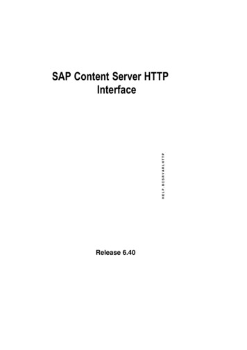
Chapter 1: IntroductionFront FeaturesThe illustration below shows the features included on the front of the chassis.Control PanelPCI SlotI/O PortsFigure 1-2. SC505-203B Chassis Front ViewFront Chassis FeaturesItemFeatureDescription1Control PanelFront control panel with LEDs and buttons (see preceding page)2I/O PortsInput/Output ports (see next page and Section 4.3 for details)3PCI SlotSlot for an expansion card145623Figure 1-3. Front Input/Output PortsFront Input/Output PortsItemDescriptionItemDescription1IPMI LAN4LAN1/22USB75LAN3/43USB66VGA11
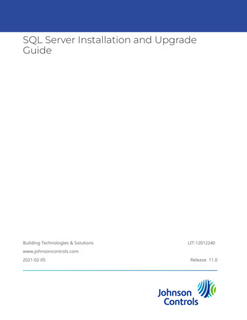
A Server AS -5019D-FTN4 User's ManualChassis RearThe illustration below shows the features included on the rear of the chassis. Power supplymodules display status lights.1Figure 1-4. SC505-203B Rear ViewChassis Rear FeaturesItemFeaturesDescription1Power SupplyFixed internal module12
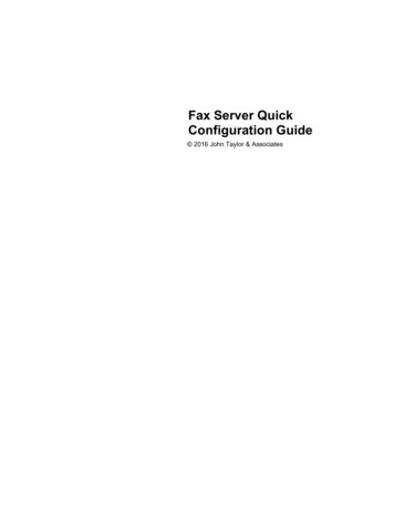
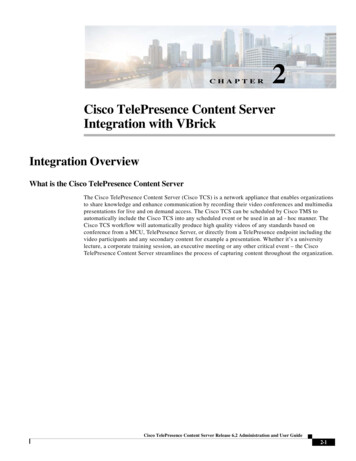
Chapter 1: Introduction1.5 Motherboard LayoutBelow is a layout of the M11SDV-8C-LN4F motherboard with jumper, connector and LEDlocations shown. See the table on the following page for descriptions. For detailed descriptions,pinout information and jumper settings, refer to Chapter 4.VGALED1IPMI LANLEDM1JPCIE1USB6/7 (3.1 Gen 1)LAN1/2LAN3/4UIDVGALED1LED2M2 SRW1UIDLED2LEDM1M2 SRW1JBM2i350JBM2IPMI LANUSB 6/7(3.0)LAN 1/2LAN 3/4BMCAST25001BAR 4FUSB4/5USB 4/5JSMBJSMBDESIGNED IN USAREV:1.01AJI2C2JI2C2JD1: 1-3:PWR LED4-7:SPEAKERJI2C1JI2C1JBM1JBM1JPCIE1CPU SLOT7 PCI-E 3.0 X16JPG1: 1-2:ENABLEVGA JPV1BT1PWR RST X OH/FF NIC NIC HDD PWR X NMI1 LED LEDUID2ONJGP1USB0/1JF1COM1FANAPJ1PJ1USB VR1JPI2C1JMD2PCI-E 3.0 X4 M.2-HCJWD1JWD1JPI2C1JPG1JMD2JPG1JWD1:WATCH DOG1-2:RST2-3:NMIJD1JD1FAN1LED3JF1USB 2/3SATA3SUPER STBY1FAN2SATA POWERFAN1JSTBY1JBT1FAN2BT1Figure 1-5. Motherboard Layout13
A Server AS -5019D-FTN4 User's ManualQuick ReferenceJumperDescriptionDefault SettingJBM1Disable Share LANPin 1-2 Open (Enable)JBM2Disable IPMI/Share LANPin 1-2 Open (Enable)JBT1CMOS ClearOpen: Normal, Closed: Clear CMOSJI2C1, JI2C2SMB to PCI-E Slots Enable/DisablePins 2-3 (Disabled)JPG1Onboard VGA Enable/DisablePins 1-2 (Enabled)JVRM1VRM SMB Clock (to BMC or PCH)Pins 1-2 (Normal)JVRM2VRM SMB Data (to BMC or PCH)Pins 1-2 (Normal)JWD1Watch Dog TimerPins 1-2 (Reset)LEDDescriptionStatusLED1UID LEDSolid Blue: Unit IdentifiedLED2Overheat (OH)/PWR Fail/Fan Fail LEDSolid Red: OverheatBlinking Red: PWR Fail or Fan FailLED3Power LEDSolid Green: Power OnLEDM1BMC HeartbeatBlinking Green: BMC NormalConnectorDescriptionBT1Onboard BatteryCOM1RS232 COM Port HeaderFAN1 - FAN2, FANACPU/System Fan HeadersIPMI LANDedicated IPMI LAN PortJD1Pins 1-2: PWR LED, Pin 4-7: SpeakerJF1Front Control Panel HeaderJGP18-bit General Purpose I/O HeaderJMD2M.2 Slot 2280 M-key (PCIe x 4/SATA 3.0)JPCIE1PCI-E 3.0 x 16 SlotJPI C1Power I2C System Management Bus (Power SMB) HeaderJPV18-pin 12V DC Power Input (Required for 12V only or 24-pin ATX power)JSMBSystem Management Bus HeaderJSTBY1Standby Power ConnectorJTPM1Trusted Platform Module (TPM)/Port 80 ConnectorLAN1 - LAN41 GbE LAN (RJ45) PortsPJ1Header for ATX Power Signal 5VSTBY/Power ON/Power GOOD/Ground; 24pin ATX to4pin power cable for PJ1 (Supermicro P/N: CBL-PWEX-1063)SATA0 - SATA3SATA 3.0 PortsUIDUnit Identifier SwitchUSB0-5USB 2.0 HeaderUSB6/7Back Panel USB 3.0 PortsVGAVGA Port (back panel)214
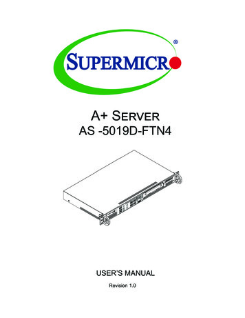
Chapter 1: IntroductionChipset Block DiagramMEM DIMMAMEM DIMMBMEM DIMMCMEM DIMMD2666MHzSVID3 Phase VRSVI28.0GT/sGroup B 0 15BGALPCPCIe x 1HUBPCIe3.0 x4 / SATA x 1M.2 M PCIe x4USB 0 HSD0USB 0 HSD1PCIe3.0 x48.0GT/s Group A 12 15I350 PCIe x4CPU1AMDPCIe3.0 x16Slot 1 PCIe x16 ( or 2 x 8 )RJ45 x42666MHzHUB8.0GT/s or 6Gb/s Group A 4 7SATA-III6Gb/s4 X SATA-IIIHeaderUSB2 x2HeaderUSB2 x2Group A 0 3USB3.0 USB 1 SS 0 & USB 1 HSD05Gbps USB 1 SS 1 & USB 1 HSD1USB2.0500MbpsRear USB 3.0 x 2Header USB 2.0 x 2TPM1.2 HeaderRJ45VGA (KVM)REAR IODedicated LAN USB3.0COM1 (Header)AST2500Health Info.1G LAN 1G LANSPIVGAFLASHSPI 128MbFigure 1-6. Chipset Block DiagramNote: This is a general block diagram and may not exactly represent the features on yourmotherboard. See the previous pages for the actual specifications of your motherbotard.15
A Server AS -5019D-FTN4 User's Manual1.6 Where to Get Replacement ComponentsIf you need replacement parts for your system, to ensure the highest level of professionalservice and technical support, purchase exclusively from our Supermicro AuthorizedDistributors/System Integrators/Resellers. A list can be found at: http://www.supermicro.com.Click the "Where to Buy" link.1.7 Returning Merchandise for ServiceA receipt or copy of your invoice marked with the date of purchase is required before anywarranty service will be rendered. You can obtain service by calling your vendor for a ReturnedMerchandise Authorization (RMA) number. When returning to the manufacturer, the RMAnumber should be prominently displayed on the outside of the shipping carton, and mailedprepaid or hand-carried. Shipping and handling charges will be applied for all orders thatmust be mailed when service is complete.For faster service, RMA authorizations may be requested online (http://www.supermicro.com/support/rma/).Whenever possible, repack the chassis in the original Supermicro carton, using the originalpackaging material. If these are no longer available, be sure to pack the chassis securely,using packaging material to surround the chassis so that it does not shift within the cartonand become damaged during shipping.This warranty only covers normal consumer use and does not cover damages incurred inshipping or from failure due to the alteration, misuse, abuse or improper maintenance ofproducts.During the warranty period, contact your distributor first for any product problems.16
A Server AS -5019D-FTN4 User's ManualChapter 2Server Installation2.1 OverviewThis chapter provides advice and instructions for mounting your system in a server rack.Caution: Electrostatic Discharge (ESD) can damage electronic components. To prevent suchdamage to PCBs (printed circuit boards), it is important to use a grounded wrist strap, handleall PCBs by their edges and keep them in anti-static bags when not in use.2.2 Preparing for SetupThe box in which the system was shipped should include the rackmount hardware needed toinstall it into the rack. Please read this section in its entirety before you begin the installation.Choosing a Setup Location The system should be situated in a clean, dust-free area that is well ventilated. Avoid areaswhere heat, electrical noise and electromagnetic fields are generated. Leave enough clearance in front of the rack so that you can open the front door completely( 25 inches) and approximately 30 inches of clearance in the back of the rack to allowsufficient space for airflow and access when servicing. This product should be installed only in a Restricted Access Location (dedicated equipmentrooms, service closets, etc.). This product is not suitable for use with visual display workplace devices according to §2of the German Ordinance for Work with Visual Display Units.Rack Precautions Ensure that the leveling jacks on the bottom of the rack are extended to the floor so thatthe full weight of the rack rests on them. In single rack installations, stabilizers should be attached to the rack. In multiple rack installations, the racks should be coupled together.17
Chapter 2: Server InstallationServer Precautions Review the electrical and general safety precautions in Appendix B. Determine the placement of each component in the rack before you install the rails. Install the heaviest server components at the bottom of the rack first and then work yourway up. Use a regulating uninterruptible power supply (UPS) to protect the server from powersurges and voltage spikes and to keep your system operating in case of a power failure. Allow any drives and power supply modules to cool before touching them. When not servicing, always keep the front door of the rack and all covers/panels on theservers closed to maintain proper cooling.Rack Mounting ConsiderationsAmbient Operating TemperatureIf installed in a closed or multi-unit rack assembly, the ambient operating temperature ofthe rack environment may be greater than the room's ambient temperature. Therefore,consideration should be given to installing the equipment in an environment compatible withthe manufacturer’s maximum rated ambient temperature (Tmra).AirflowEquipment should be mounted into a rack so that the amount of airflow required for safeoperation is not compromised.Mechanical LoadingEquipment should be mounted into a rack so that a hazardous condition does not arise dueto uneven mechanical loading.Circuit OverloadingConsideration should be given to the connection of the equipment to the power supply circuitryand the effect that any possible overloading of circuits might have on overcurrent protectionand power supply wiring. Appropriate consideration of equipment nameplate ratings shouldbe used when addressing this concern.18
A Server AS -5019D-FTN4 User's ManualReliable GroundA reliable ground must be maintained at all times. To ensure this, the rack itself should begrounded. Particular attention should be given to power supply connections other than thedirect connections to the branch circuit (i.e. the use of power strips, etc.).To prevent bodily injury when mounting or servicing this unit in a rack, you must takespecial precautions to ensure that the system remains stable. The following guidelinesare provided to ensure your safety: This unit should be mounted at the bottom of the rack if it is the only unit in the rack. When mounting this unit in a partially filled rack, load the rack from the bottom to the topwith the heaviest component at the bottom of the rack. If the rack is provided with stabilizing devices, install the stabilizers before mounting orservicing the unit in the rack.19
Chapter 2: Server Installation2.3 Installing the System Into a RackThis section provides information on installing the AS -5019D-FTN4 system into a rack.The chassis has two rack mounting "ear" brackets, which are located on each side of thefront of the chassis. To mount the system into a rack, screw these brackets directly to thefront of the rack, two screws for each bracket.Figure 2-1. Installing the Server into a RackNote: Figures are for illustrative purposes only. Always install servers to the bottom of a rackfirst.20
A Server AS -5019D-FTN4 User's ManualInstalling the Server into a Telco RackIf you are installing the system into a two post (Telco) rack, follow the directions given on theprevious pages for rack installation. The only difference in the installation procedure will bethe positioning of the rack brackets to the rack. They should be spaced apart just enough toaccommodate the width of the telco rack.Figure 2-2. Installing the Server into a Telco RackNote: Figure is for illustrative purposes only. Always install servers to the bottom of a rack first.21
A Server AS -5019D-FTN4 User's ManualChapter 3Maintenance and Component InstallationThis chapter provides instructions on installing and replacing main system components. Toprevent compatibility issues, only use components that match the specifications and/or partnumbers given.Installation or replacement of most components require that power first be removed from thesystem. Please follow the procedures given in each section.3.1 Removing PowerUse the following procedure to ensure that power has been removed from the system. Thisstep is necessary when removing or installing non hot-swap components or when replacinga non-redundant power supply.1. Use the operating system to power down the system.2. After the system has completely shut-down, disconnect the AC power cord from thepower strip or outlet.3. Disconnect the power cord from the power supply module.22
Chapter 3: Maintenance and Component Installation3.2 Accessing the SystemThe SC505 chassis features a removable top cover to allow access to components inside.Removing the Top Cover1. Remove the five screws that hold the chassis cover in place. There are two screws oneach side of the chassis, and one screw on the back.2. Slide the cover toward the rear and lift it off the chassis.Check that all ventilation openings on the top cover and the top of the chassis are clear andunobstructed.Caution: Except for short periods of time, do not operate the server without the cover in p
Contacting Supermicro Contacting Supermicro Headquarters Address: Super Micro Computer, Inc. 980 Rock Ave. San Jose, CA 95131 U.S.A. Tel: 1 (408) 503-8000 Fax: 1 (408) 503-8008 Email: marketing@supermicro.com (General Information) support@supermicro.com (Technical Support) Website: www.supermicro.com Europe Address: Super Micro Computer B.V.