Transcription
X9SRW-FUSER’S MANUALRevision 1.1
The information in this User’s Manual has been carefully reviewed and is believed to be accurate.The vendor assumes no responsibility for any inaccuracies that may be contained in this document,makes no commitment to update or to keep current the information in this manual, or to notify anyperson or organization of the updates. Please Note: For the most up-to-date version of thismanual, please see our web site at www.supermicro.com.Super Micro Computer, Inc. ("Supermicro") reserves the right to make changes to the productdescribed in this manual at any time and without notice. This product, including software and documentation, is the property of Supermicro and/or its licensors, and is supplied only under a license.Any use or reproduction of this product is not allowed, except as expressly permitted by the termsof said license.IN NO EVENT WILL SUPER MICRO COMPUTER, INC. BE LIABLE FOR DIRECT, INDIRECT,SPECIAL, INCIDENTAL, SPECULATIVE OR CONSEQUENTIAL DAMAGES ARISING FROM THEUSE OR INABILITY TO USE THIS PRODUCT OR DOCUMENTATION, EVEN IF ADVISED OFTHE POSSIBILITY OF SUCH DAMAGES. IN PARTICULAR, SUPER MICRO COMPUTER, INC.SHALL NOT HAVE LIABILITY FOR ANY HARDWARE, SOFTWARE, OR DATA STORED OR USEDWITH THE PRODUCT, INCLUDING THE COSTS OF REPAIRING, REPLACING, INTEGRATING,INSTALLING OR RECOVERING SUCH HARDWARE, SOFTWARE, OR DATA.Any disputes arising between manufacturer and customer shall be governed by the laws of SantaClara County in the State of California, USA. The State of California, County of Santa Clara shallbe the exclusive venue for the resolution of any such disputes. Supermicro's total liability for allclaims will not exceed the price paid for the hardware product.FCC Statement: This equipment has been tested and found to comply with the limits for a Class Bdigital device pursuant to Part 15 of the FCC Rules. These limits are designed to provide reasonable protection against harmful interference in a residential installation. This equipment generates,uses, and can radiate radio frequency energy and, if not installed and used in accordance with themanufacturer’s instruction manual, may cause interference with radio communications. However,there is no guarantee that interference will not occur in a particular installation. If this equipmentdoes cause harmful interference to radio or television reception, which can be determined by turning the equipment off and on, you are encouraged to try to correct the interference by one or moreof the following measures: Reorient or relocate the receiving antenna. Increase the separation between the equipment and the receiver. Connect the equipment into an outlet on a circuit different from that to which thereceiver is connected. Consult the dealer or an experienced radio/television technician for help.California Best Management Practices Regulations for Perchlorate Materials: This Perchlorate warning applies only to products containing CR (Manganese Dioxide) Lithium coin cells. “PerchlorateMaterial-special handling may apply. See ING: Handling of lead solder materials used in this product may expose you to lead, a chemical known to the State ofCalifornia to cause birth defects and other reproductive harm.Manual Revision 1.1Release Date: December 23, 2013Unless you request and receive written permission from Super Micro Computer, Inc., you may notcopy any part of this document. Information in this document is subject to change without notice.Other products and companies referred to herein are trademarks or registered trademarks of theirrespective companies or mark holders.Copyright 2013 by Super Micro Computer, Inc. All rights reserved.Printed in the United States of America
PrefacePrefaceThis manual is written for system integrators, PC technicians andknowledgeable PC users. It provides information for the installation and use of theX9SRW motherboard series.About This MotherboardTheX9SRW motherboard series supports a single Intel E5-1600/E52600 series processor (2011-pin, Socket R). With the Intel C600 series chipsetbuilt in, the X9SRW Motherboard series offers top-of-the-line system performanceand storage capability. Features such as support for up to 256GB of memory, dual1Gb LAN, eight (8) USB ports, and an IPMI port make the X9SRW series ideal forhigh end rack-mounted single-processor platforms.Please refer to our website (http://www.supermicro.com/products/) for processorand memory support updates.*This product is intended to be installed and serviced by professional technicians.Manual OrganizationChapter 1 describes the features, specifications and performance of the motherboard, and provides detailed information on the Intel Patsburg chipset.Chapter 2 provides hardware installation instructions. Read this chapter when installing the processor, memory modules and other hardware components into thesystem. If you encounter any problems, see Chapter 3, which describes troubleshooting procedures for video, memory and system setup stored in the CMOS.Chapter 4 includes an introduction to the BIOS, and provides detailed informationon running the CMOS Setup utility.Appendix A provides BIOS Error Beep Codes.Appendix B lists software program installation instructions.Appendix C contains the UEFI BIOS Recovery instructions.iii
X9SRW Motherboard Series User’s ManualConventions Used in the Manual:Special attention should be given to the following symbols for proper installation andto prevent damage done to the components or injury to yourself:Danger/Caution: Instructions to be strictly followed to prevent catastrophicsystem failure or to avoid bodily injuryWarning: Critical information to prevent damage to the components ordata loss.Important: Important information given to ensure proper system installation or to relay safety precautions.Note: Additional Information given to differentiate various models or provides information for correct system setup.iv
Contacting SupermicroContacting SupermicroHeadquartersAddress:Super Micro Computer, Inc.980 Rock Ave.San Jose, CA 95131 U.S.A.Tel: 1 (408) 503-8000Fax: 1 (408) 503-8008Email:marketing@supermicro.com (General Information)support@supermicro.com (Technical Support)Web Site:www.supermicro.comEuropeAddress:Super Micro Computer B.V.Het Sterrenbeeld 28, 5215 ML's-Hertogenbosch, The NetherlandsTel: 31 (0) 73-6400390Fax: 31 (0) 73-6416525Email:sales@supermicro.nl (General Information)support@supermicro.nl (Technical Support)rma@supermicro.nl (Customer Support)Web Site:www.supermicro.comAsia-PacificAddress:Super Micro Computer, Inc.3F, No. 150, Jian 1st Rd.Zhonghe Dist., New Taipei City 235Taiwan (R.O.C)Tel: 886-(2) 8226-3990Fax: 886-(2) 8226-3992Email:support@supermicro.com.twTel: 886-(2)-8226-3990Web Site:www.supermicro.com.twv
X9SRW Motherboard Series User’s ManualTable of ContentsPrefaceChapter 1 Introduction1-1Overview. 1-11-2Chipset Overview . 1-101-3Special Features.1-111-4PC Health Monitoring.1-111-5ACPI Features. 1-121-6Power Supply. 1-121-7Super I/O. 1-13Chapter 2 Installation2-1Static-Sensitive Devices. 2-1Precautions. 2-1Unpacking. 2-12-2Processor and Heatsink Installation. 2-2The LGA2011 Socket . 2-2Opening the LGA2011 Socket . 2-3Installing the LGA2011 Processor . 2-5Installing a Passive CPU Heatsink. 2-7Removing the Heatsink. 2-82-3Installing DDR3 Memory. 2-9DIMM Installation. 2-9Removing Memory Modules. 2-9Memory Support. 2-10Memory Population Guidelines.2-112-4Motherboard Installation. 2-12Tools Needed. 2-12Location of Mounting Holes. 2-12Installing the Motherboard. 2-132-5Connectors/IO Ports. 2-14Motherboard I/O Backpanel. 2-14Universal Serial Bus (USB). 2-15Ethernet Ports. 2-16Serial Port. 2-16Video (VGA/CRT) Connector. 2-16Front Control Panel. 2-17Front Control Panel Pin Definitions. 2-18vi
Table of ContentsNMI Button. 2-18Power LED . 2-18HDD LED. 2-18NIC1/NIC2 (LAN1/LAN2). 2-19Overheat (OH)/Fan Fail/UID LED. 2-19Reset Button . 2-20Power Button . 2-202-6Connecting Cables & Optional Devices. 2-21ATX Main PWR (JPW1) & CPU PWR Connectors (JPW2). 2-21Fan Headers (FAN1 6). 2-22Chassis Intrusion (JL1). 2-22Speaker (JD1). 2-23Legacy Wake-On-LAN Header (JSTBY). 2-23Power Supply I2C (JPI2C). 2-24DOM PWR Connector (JSD1). 2-24T-SGPIO 1/2 & 3-SGPIO 1/2 Headers. 2-25TPM Header (JTPM1). 2-25Overheat/Fan Fail LED (JOH1). 2-262-7Jumper Settings. 2-27Explanation of Jumpers. 2-27LAN Port Enable/Disable (JPL1). 2-27Clear CMOS (JBT1). 2-28PCI Slot SMB Enable (JI2C2/JI2C3). 2-28Watch Dog Reset (JWD). 2-29BMC Enable/Disable (JPB1). 2-29Onboard VGA Enable (JPG1). 2-30Unit Identifier Switch (UID). 2-30BIOS Recovery (JP3). 2-31ME Recovery (JPME1). 2-31VRM SMB Clock/Data (J29/J30). 2-312-8Onboard Indicators. 2-32LAN Port LEDs. 2-32Onboard Power LED (LE1). 2-32Rear Unit ID LED (LE2). 2-33IPMI Heartbeat LED (BD1). 2-33Onboard Standby Power LED (LED2). 2-332-9SATA Connections. 2-34SATA/SAS Connections . 2-34vii
X9SRW Motherboard Series User’s ManualChapter 3 Troubleshooting3-1Troubleshooting Procedures. 3-13-2Technical Support Procedures. 3-33-3Frequently Asked Questions. 3-43-4Battery Removal and Installation. 3-63-5Returning Merchandise for Service. 3-7Chapter 4 BIOS4-1Introduction. 4-14-2Main Setup. 4-24-3Advanced Setup Configurations. 4-44-4Event Logs. 4-194-5IPMI . 4-214-6Boot Settings. 4-234-8Security Settings. 4-244-8Save & Exit. 4-25Appendix A BIOS Error Beep CodesA-1BIOS Error Beep Codes.A-1Appendix B Software Installation InstructionsB-1Installing Drivers.B-1B-2Configuring SuperDoctor III.B-2Appendix C UEFI BIOS Recovery InstructionsAn Overview to the UEFI BIOS.C-1How to Recover the UEFI BIOS Image (the Main BIOS Block).C-1To Recover the Main BIOS Block Using a USB-Attached Device.C-1viii
Chapter 1: IntroductionChapter 1Introduction1-1OverviewChecklistCongratulations on purchasing your computer motherboard from an acknowledgedleader in the industry. Supermicro boards are designed with the utmost attention todetail to provide you with the highest standards in quality and performance.Please check that the following items have all been included with your motherboard.If anything listed here is damaged or missing, contact your retailer.The following items are included in the retail box: One (1) Supermicro Mainboard Six (6) SATA cables One (1) I/O shield One (1) Supermicro CD containing drivers and utilitiesNote: For your system to work properly, please follow the links below todownload all necessary drivers/utilities and the user's manual for yourmotherboard. SMCI product manuals: http://www.supermicro.com/support/manuals/ Product Drivers and utilities: ftp://ftp.supermicro.com/Warning: For safety considerations, please refer to the complete list ofsafety warnings posted on the Supermicro website at http://www.supermicro.com/about/policies/safety information.cfm.If you have any questions, please contact our support team at support@supermicro.com.1-1
X9SRW Motherboard Series User’s ManualMotherboard ImageNote: All graphics shown in this manual were based upon the latest PCBRevision available at the time of publishing of the manual. The motherboardyou've received may or may not look exactly the same as the graphicsshown in this manual.1-2
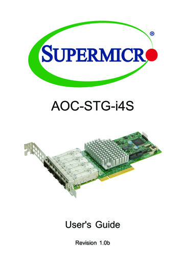
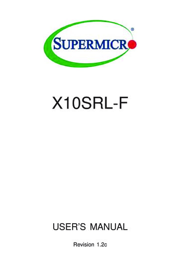
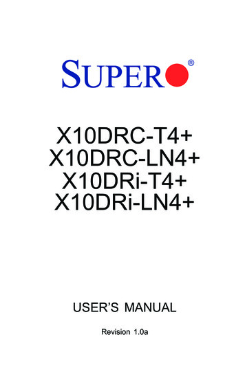
Chapter 1: IntroductionMotherboard Layout14VGAJVGA1IPMI 2-3:DisableJPG1: LAN1LAN2J17JI2C3JI2C2SXB1AJWP1:WRITE PROTECTJ26BD1USBJ23JWDJPL1JOH1:OVER HEAT LEDSXB1A: LEFT WIO UPSXB1B: LEFT WIO MIDDLE11JPG1SXB2SXB2: RIGHT WIO1USBJOH1J30BT1133J29JSTBY1:STAND BY POWER FOR DOM13SAS4JTPM1JBT1:CMOS CLEARJPB1: BMC1-2:ENABLE2-3:DISABLEJPME1:ON:ME RECOVERYOFF:NORMALJTPM1: TPM/PORT80SAS3 JWD:WATCH DOG D1:1-2:PWR 2C1JTPM1:TPM/PORT8018SAS171LE1H-HS2 25SAS2CPUJ1J2J3J4DESIGNED IN SATA2CLOSE 1stR136C241I-SATA51JWF1I-SATA4Socket RLGA 2011CPUJPWR11OPEN JF11FAN1FAN3JL1 :CHASSIS INTRUSIONJL119Important Notes to the User See Chapter 2 for detailed information on jumpers, I/O ports and JF1 frontpanel connections. " " indicates the location of "Pin 1". Jumpers not indicated are for testing only.1-3
X9SRW Motherboard Series User’s ManualMotherboard Quick D2JUSBKMLED214VGAJVGA1JPG1: VGA1-2:Enable2-3:DisableJLAN2JCOM1IPMI PMBJIPMB1J17JWP1:WRITE 1B: LEFT WIO MIDDLESXB2: RIGHT WIO313JSTBY1JD1:1-2:PWR STBY1:STAND BY POWER FOR DOMJPME1JTPM1: TPM/PORT80JPB11 SAS433JBT1:CMOS CLEARJPB1: BMC1-2:ENABLE2-3:DISABLEJPME1:ON:ME T1JP3SXB1B11JPG1JWD:WATCH DOG TIMER1-2:RST(DEFAULT)2-3:NMISAS31USBJOH1:OVER HEAT LEDSXB1A: LEFT WIO -SGPIO4T-SGPIO3T-SGPIO2T-SGPIO1LE1I-SAS1H-HS2 25SAS2CPUJ1J2J3J4DESIGNED IN M3AI-SATA3I-SATA2CLOSE 1stR136C241I-SATA5Socket RLGA 2011CPU1JWF1I-SATA4JSD1JPWR11JPW2OPEN 1stDIMM1ADIMM1BDIMM2BDIMM2AI-SATA0 I-SATA1I-SATA2 I-SATA3I-SATA4 AN1FAN3JL1 :CHASSIS INTRUSIONJL119JF1FAN31-4FAN2FAN1
Chapter 1: IntroductionMotherboard Headers/ConnectorsConnectorDescriptionI-SAS0 I-SAS3 (SATA 3.0)I-SATA 2.0 ports (supports up to 3Gb/s)I-SATA0, I-SATA1 (SATA 3.0)I-SATA2 I-SATA5 (SATA 2.0)Internal SATA ports (I-SATA0 and I-SATA1 supports up to6Gb/s), I-SATA2 I-SATA5 supports up to 3Gb/s)FAN1 FAN5Headers for system cooling fansJSD1SATA DOM (Disk On Module) Power ConnectorJL1Chassis Intrusion HeaderJF1Front Panel Control HeaderJPW124-pin Main ATX Power ConnectorJPW28-pin Secondary Power ConnectorJD1Power LED / Speaker Header (Pins 4 7: External Speaker)JPI2C1Power Supply SMBus I2C HeaderT-SGPIO1 4Serial Link General Purpose I/O Headers (5V Gen1/Gen 2)JTPM1Trusted Platform Module (TPM) HeaderJSTBY1Legacy Wake On LAN HeaderUSB0/1, USB2/3Back panel USB 2.0 portsUSB4/5, USB4/5Internal USB 2.0 headersJIPMBSystem Management Bus Header for the IPMI SlotJCOM1Back panel Serial Port ConnectorIPMIBack panel IPMI LAN PortJLAN1/JLAN2Back panel LAN1 / LAN2 Ethernet PortsJVGA1Back panel VGA PortJOH1Overheat LED/Fan FailBT1System BatterySP1Internal Speaker / BuzzerSXB1A, SXB1BSlot for Supemicro riser card P/N RSC-R1UW-2E16SXB2Slot for Supemicro riser card P/N RSC-R1UW-E8R1-5
X9SRW Motherboard Series User’s ManualMotherboard JumpersJumperDescriptionDefaultJI2C2/JI2C3SMB to PCI SlotsOn (EnabledJPG1Onboard VGA EnablePins 1-2 (On)JPL1LAN1 EnablePins 1-2 (Enabled)JPME1Intel ME Mode SelectPins 1-2 (Normal)UIDUnit ID SwitchOff (Disabled)JWDWatch Dog Timer ResetPins 1-2 (Reset)JPB1IPMI/BMC EnablePins 1-2 (Enabled)JP3BIOS RecoverPins 2-3 (Normal)JWP1BIOS Write ProtectPins 1-2 (Normal)JBT1CMOS ClearSee Chapter 2J29VRM SMB Clock (to BMC or PCH)Pins 1-2 (BMC, Normal)J30VRAM SMB Data (to BMC or PCH)Pins 1-2 (BMC, Normal)Motherboard LED by 3.3V PowerGreen/SteadyStandby PowerLE1Power LEDGreen/SteadySystem is On/RunningLE2UID LEDBlue/SteadyUID Switch is OnBD1IPMI HeartbeatGreen/BlinkingIPMI is enabled1-6
Chapter 1: IntroductionMotherboard FeaturesCPUSupports a single Intel E5-1600/E5-2600 series processor (2011-pin, Socket R)MemoryEight (8) DIMM slots support up to 256GB of DDR3 Unbuffered, ECC RDIMM memory or 64GB of DDR3 Unbuffered,ECC/non-ECC UDIMM memory, 1066/1333/1600MHz.Supports dual-channel memory busDIMM sizesUDIMM1GB, 2GB, 4GB, 8GB, 16GBRDIMM2GB, 4GB, 8GB, 16GB, 32GB, 64GBChipsetIntel C600-D or C600-AExpansionPCI Slots (using riser cards)Two (2) PCI-Express 3.0 x16 Slot, using Supemicro risercard P/N RSC-R1UW-2E16One (1) PCI-Express 2.0 x8 Slot, using Supermicro risercard P/N RSC-R1UW-E8RNetwork ConnectionsIntegrated LANOne (1) Intel i350 Dual Gb LANI/O DevicesSATA ConnectionsSATATwo SATA 3.0 ports (6Gb/s)RAID (0,1)Four SATA 2.0 ports (3Gb/s)RAID (0,1,10,5)SCUFour SATA ports (3Gb/s) via SCURAID (0,1,10,5)USB DevicesTwo (2) USB 2.0 ports on the rear I/O panelSix (6) USB 2.0 headers for front panel accessSerial (COM) PortsOne (1) Fast UART 16550 connection on the I/O backpanel (COM1)BIOS32 Mb SPI AMI BIOS SM Flash BIOSPlug and Play APM 1.2, DMI 2.3, PCI 2.2, ACPI 1.0/2.0,USB Keyboard and SMBIOS 2.3Power ConfigurationACPI/ACPM Power ManagementWake On LAN (WOL) HeaderKeyboard Wake-up from Soft-Off1-7
X9SRW Motherboard Series User’s ManualCPU Fan Auto-off in Sleep ModePower-on mode for AC power recoveryPC Health MonitoringCPU & Chassis MonitoringOnboard voltage monitors for CPU core, 1.8V, 3.3V, 5V, /-12V, 3.3V Stdby, 5V Stdby, VBAT, Memory,ChipsetCPU 5-phase switching voltage regulatorCPU/System overheat LED and controlCPU Thermal Trip supportCPU & Chassis Environment MonitorFan ControlFan status monitoring with firmware 4-pin (Pulse WidthModulation) fan speed controlLow noise fan speed controlSystem ManagementPECI 2.0 supportSystem resource alert via SuperDoctor IIISuperDoctor III, Watch Dog, NMIChassis Intrusion header and detectionCD UtilitiesBIOS flash upgrade utilityDrivers and software for Intel C204 chipset utilitiesOtherROHS 6/6 (Full Compliance, Lead Free)TPM 1.2 header on boardDOM (Disk on Module) Power Connector SupportFCC B, EuP Lot 6, WHQLDimensionsWIO form factor (8.15" x 13.05")1-8
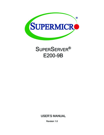
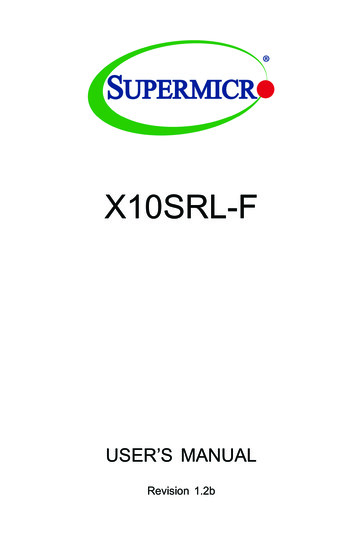
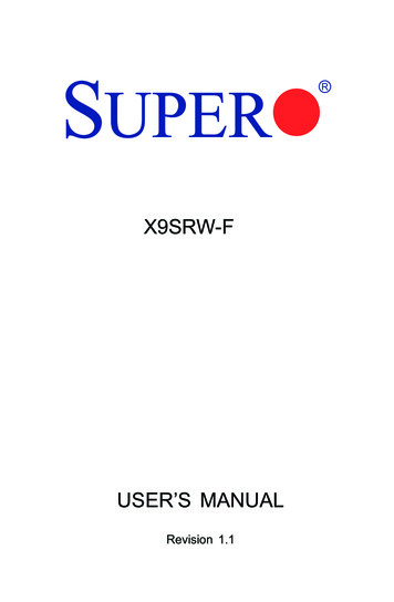
Chapter 1: IntroductionMotherboard Block DiagramX9SRW-FVR125 ge-EP8 SNB COREDDR-III#3A #3B #1ADMI2#1BDDRIII1066/1333/1600#2P0P1PCI-E X16SXB1PCI-E X16 G3PCI-E X16 G3SXB2PCI-E X8PCI-E X8G3 (PE1)DMI24GB/sDMI2PCI-E X4SASPORTs#0 3SASSASPORTs#4 7G2LANLANE1/2/3/4i350LANE6PCH-APATSBURGSSB3.0 Gb/S6.0 Gb/SFOR PORT 0/1SATALANE5#5#4#3#2#1#0284 Rear4 FrontPCI 32bitVGACOM1ExternalUSB 2.0SPIUSBBMCSIOW83527optionSystem Block DiagramNote: This is a general block diagram and may not exactly representthe features on your motherboard. See the Motherboard Featurespages for the actual specifications of each motherboard.1-9
X9SRW Motherboard Series User’s Manual1-2Chipset OverviewThe Intel C600 series is a single chip solution that is designed for dedicated servers and workstations. It supports high-speed SAS, SATA and advanced requirements for Intel Xeon platforms. Intel C600 Chipset FeaturesDirect Media Interface (up 5 Gt/s transfer, Full Duplex) Intel Matrix Storage Technology and Intel Rapid Storage Technology Intel I/O Virtualization (VT-d) Support Intel Trusted Execution Technology Support PCI Express 2.0 Interface (up to 5.0 GT/s) PCI Express 3.0 Interface (up to 8.0 GT/s) 4 SATA 2.0 ports, 2 SATA 3.0 ports (up to 6Gb/s) Advanced Host Controller Interface (AHCI)1-10
Chapter 1: Introduction1-3Special FeaturesRecovery from AC Power LossBasic I/O System (BIOS) provides a setting for you to determine how the systemwill respond when AC power is lost and then restored to the system. You canchoose for the system to remain powered off (in which case you must press thepower switch to turn it back on), or for it to automatically return to a power-on state.See the Advanced BIOS Setup section to change this setting. The default settingis Last State.1-4PC Health MonitoringThis section describes the PC health monitoring features of the board. All have anonboard System Hardware Monitoring chip that supports PC health monitoring. Anonboard voltage monitor will scan these onboard voltages continuously: 1.8V, 3.3V, 5V, /-12V, 3.3V Stdby, 5V Stdby, VBAT, Memory, Chipset. Once a voltage becomes unstable, a warning is given, or an error message is sent to the screen. Theuser can adjust the voltage thresholds to define the sensitivity of the voltage monitor.Fan Status Monitor with Firmware ControlPC health monitoring in the BIOS can check the RPM status of the cooling fans. Theonboard CPU and chassis fans are controlled by Thermal Management via BIOS(under the Hardware Monitoring section in the Advanced Setting).Environmental Temperature ControlThe thermal control sensor monitors the CPU temperature in real time and will turnon the thermal control fan whenever the CPU temperature exceeds a user-definedthreshold. The overheat circuitry runs independently from the CPU. Once the thermal sensor detects that the CPU temperature is too high, it will automatically turnon the thermal fans to prevent the CPU from overheating. The onboard chassisthermal circuitry can monitor the overall system temperature and alert the user whenthe chassis temperature is too high.Note: To avoid possible system overheating, please be sure to provideadequate airflow to your system.System Resource AlertThis feature is available when the system is used with SuperDoctor III in theWindows OS environment or used with SuperDoctor II in Linux. SuperDoctor1-11
X9SRW Motherboard Series User’s Manualis used to notify the user of certain system events. For example, you can alsoconfigure SuperDoctor to provide you with warnings when the system temperature,CPU temperatures, voltages and fan speeds go beyond predefined thresholds.1-5ACPI FeaturesACPI stands for Advanced Configuration and Power Interface. The ACPI specification defines a flexible and abstract hardware interface that provides a standardway to integrate power management features throughout a PC system, includingits hardware, operating system and application software. This enables the systemto automatically turn on and off peripherals such as CD-ROMs, network cards, harddisk drives and printers.In addition to enabling operating system-directed power management, ACPI alsoprovides a generic system event mechanism for Plug and Play, and an operatingsystem-independent interface for configuration control. ACPI leverages the Plug andPlay BIOS data structures, while providing a processor architecture-independentimplementation that is compatible with Windows XP, Windows Vista and Windows2008 Operating Systems.Slow Blinking LED for Suspend-State IndicatorWhen the CPU goes into a suspend state, the chassis power LED will start to blinkto indicate that the CPU is in suspend mode. When the user presses any key, theCPU will "wake up", and the LED will automatically stop blinking and remain on.1-6Power SupplyAs with all computer products, a stable power source is necessary for proper andreliable operation. It is even more important for process
Contacting Supermicro Contacting Supermicro Headquarters Address: Super Micro Computer, Inc. 980 Rock Ave. San Jose, CA 95131 U.S.A. Tel: 1 (408) 503-8000 Fax: 1 (408) 503-8008 Email: marketing@supermicro.com (General Information) support@supermicro.com (Technical Support) Web Site: www.supermicro.com Europe Address: Super Micro Computer B.V.