Transcription
SuperServer E200-9BUSER’S MANUALRevision 1.0
The information in this User’s Manual has been carefully reviewed and is believed to be accurate. The vendor assumesno responsibility for any inaccuracies that may be contained in this document, and makes no commitment to updateor to keep current the information in this manual, or to notify any person or organization of the updates. Please Note:For the most up-to-date version of this manual, please see our website at www.supermicro.com.Super Micro Computer, Inc. ("Supermicro") reserves the right to make changes to the product described in this manualat any time and without notice. This product, including software and documentation, is the property of Supermicro and/or its licensors, and is supplied only under a license. Any use or reproduction of this product is not allowed, exceptas expressly permitted by the terms of said license.IN NO EVENT WILL Super Micro Computer, Inc. BE LIABLE FOR DIRECT, INDIRECT, SPECIAL, INCIDENTAL,SPECULATIVE OR CONSEQUENTIAL DAMAGES ARISING FROM THE USE OR INABILITY TO USE THIS PRODUCTOR DOCUMENTATION, EVEN IF ADVISED OF THE POSSIBILITY OF SUCH DAMAGES. IN PARTICULAR, SUPERMICRO COMPUTER, INC. SHALL NOT HAVE LIABILITY FOR ANY HARDWARE, SOFTWARE, OR DATA STOREDOR USED WITH THE PRODUCT, INCLUDING THE COSTS OF REPAIRING, REPLACING, INTEGRATING,INSTALLING OR RECOVERING SUCH HARDWARE, SOFTWARE, OR DATA.Any disputes arising between manufacturer and customer shall be governed by the laws of Santa Clara County in theState of California, USA. The State of California, County of Santa Clara shall be the exclusive venue for the resolutionof any such disputes. Supermicro's total liability for all claims will not exceed the price paid for the hardware product.FCC Statement: This equipment has been tested and found to comply with the limits for a Class A digital devicepursuant to Part 15 of the FCC Rules. These limits are designed to provide reasonable protection against harmfulinterference when the equipment is operated in a commercial environment. This equipment generates, uses, and canradiate radio frequency energy and, if not installed and used in accordance with the manufacturer’s instruction manual,may cause harmful interference with radio communications. Operation of this equipment in a residential area is likelyto cause harmful interference, in which case you will be required to correct the interference at your own expense.California Best Management Practices Regulations for Perchlorate Materials: This Perchlorate warning applies onlyto products containing CR (Manganese Dioxide) Lithium coin cells. “Perchlorate Material-special handling may apply.See ING: Handling of lead solder materials used in this product may expose you to lead, achemical known to the State of California to cause birth defects and other reproductive harm.The products sold by Supermicro are not intended for and will not be used in life support systems, medical equipment,nuclear facilities or systems, aircraft, aircraft devices, aircraft/emergency communication devices or other criticalsystems whose failure to perform be reasonably expected to result in significant injury or loss of life or catastrophicproperty damage. Accordingly, Supermicro disclaims any and all liability, and should buyer use or sell such productsfor use in such ultra-hazardous applications, it does so entirely at its own risk. Furthermore, buyer agrees to fullyindemnify, defend and hold Supermicro harmless for and against any and all claims, demands, actions, litigation, andproceedings of any kind arising out of or related to such ultra-hazardous use or sale.Manual Revision 1.0Release Date: February 11, 2016mkUnless you request and receive written permission from Super Micro Computer, Inc., you may not copy any part of thisdocument. Information in this document is subject to change without notice. Other products and companies referredto herein are trademarks or registered trademarks of their respective companies or mark holders.Copyright 2016 by Super Micro Computer, Inc.All rights reserved.Printed in the United States of America
SuperServer E200-9B User's ManualPrefaceAbout this ManualThis manual is written for professional system integrators and PC technicians. It providesinformation for the installation and use of the SuperServer E200-9B. Installation andmaintainance should be performed by experienced technicians only.Please refer to the E200-9B server specifications page on our website for updates onsupported memory, processors and operating systems (http://www.supermicro.com).NotesFor your system to work properly, please follow the links below to download all necessarydrivers/utilities and the user’s manual for your server. Supermicro product manuals: http://www.supermicro.com/support/manuals/ Product drivers and utilities: ftp://ftp.supermicro.com Product safety info: http://www.supermicro.com/about/policies/safety information.cfmIf you have any questions, please contact our support team at:support@supermicro.comThis manual may be periodically updated without notice. Please check the Supermicro websitefor possible updates to the manual revision level.WarningsSpecial attention should be given to the following symbols used in this manual.Warning! Indicates important information given to prevent equipment/property damageor personal injury.Warning! Indicates high voltage may be encountered when performing a procedure.3
ContentsContentsChapter 1 Introduction1.1 Overview.71.2 Unpacking the System.71.3 System Features.81.4 Chassis Features.9Front Features.9Rear Features.91.5 Motherboard Layout.10System Block Diagram.121-6 Server Installation and Setup.13Unpacking the System.13Warnings and Precautions.13Adding Components to your System .13Installing Mounting Brackets.14Chapter 2 Maintenance and Component Installation2.1 Removing Power.152.2 Accessing the System.162.3 Motherboard Components.17Processor.17Memory Support.17Installing Memory.18Expansion Card.19Motherboard Battery.202-4 Chassis Components.21Installing the Hard Drive .21System Cooling.22Chapter 3 Motherboard Connections3.1 Power Connections.233.2 Headers and Connectors.243.3 Ports.283.4 Jumpers.29Explanation of Jumpers.293.5 LED Indicators.314
SuperServer E200-9B User's ManualChapter 4 Software4.1 Driver Installation.334.2 SuperDoctor 5.344.3 IPMI.35Chapter 5 BIOS5.1 Introduction.36Starting the Setup Utility.365.2 Main Setup.375.3 Advanced Setup Configurations.395.4 IPMI. 585.5 Security.615.6 Boot.64Appendix A BIOS Error CodesAppendix B Standardized Warning Statements for AC SystemsAppendix C System Specifications5
SuperServer E200-9B User's ManualContacting SupermicroHeadquartersAddress:Super Micro Computer, Inc.980 Rock Ave.San Jose, CA 95131 U.S.A.Tel: 1 (408) 503-8000Fax: 1 (408) 503-8008Email:marketing@supermicro.com (General Information)support@supermicro.com (Technical per Micro Computer B.V.Het Sterrenbeeld 28, 5215 ML's-Hertogenbosch, The NetherlandsTel: 31 (0) 73-6400390Fax: 31 (0) 73-6416525Email:sales@supermicro.nl (General Information)support@supermicro.nl (Technical Support)rma@supermicro.nl (Customer ss:Super Micro Computer, Inc.3F, No. 150, Jian 1st Rd.Zhonghe Dist., New Taipei City 235Taiwan (R.O.C)Tel: 886-(2) 8226-3990Fax: 886-(2) w.supermicro.com.tw6
Chapter 1: IntroductionChapter 1Introduction1.1 OverviewThe SuperServer E200-9B is a compact, embedded system comprised of the SC101S chassisand the X11SBA-LN4F single processor motherboard. Refer to our website for information onoperating systems that have been certified for use with the system (www.supermicro.com).This chapter provides a brief outline of the functions and features. In addition to the motherboardand chassis, several important parts that are included with the system are listed below.Main Parts ListDescriptionPart NumberQuantity60W DC power adapterMCP-250-10117-0N11.2 Unpacking the SystemInspect the box in which the server was shipped and note if it was damaged. If any equipmentappears damaged, file a claim with the carrier who delivered it.7
SuperServer E200-9B User's Manual1.3 System FeaturesThe following table provides an overview of the main features of the E200-9B. Please referto Appendix C for additional specifications.System FeaturesMotherboardX11SBA-LN4FChassisCompact Embedded Mini ITX Box ,SC101SCPUIntel Pentium Processor N3700 SoC (System on a Chip) in the FCBGA1170 format.FanOne 4-cm system fan, plus an option for one additional 4-cm fanMemorySupports up to 8 GB of DDR3L (1.35, Low Voltage) Dual Channel, Non-ECC SO-DIMM up to 1600MHz in twohorizontal sockets.Expansion SlotsOne mini-PCIe slot with mSATA supportHard DrivesSingle fixed 2.5" hard drive up to 15 mm thicknessPowerOne external 60 watt DC power adapterInput/Output PortsLAN: Four Gigabit portsIPMI: One dedicated LAN portUSB: Two USB3.0 ports, twon USB2.0 portsDisplay: 1x Display Port, 1x HDMI, 1x VGA (Two Independent Displays)Serial ATA: Two SATA3 (6Gbps) portsDOM: SuperDOM (Disk on Module) port with built-in powerCOM port from PIN headerDimensionsWidth 7.68" (195mm), Height 1.75" (44mm), Depth 7.68" (195mm)8
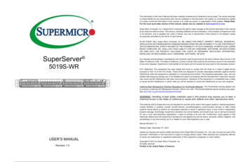
Chapter 1: Introduction1.4 Chassis FeaturesThe SC101S is a compact embedded Mini ITX chassis.Front FeaturesThe front of the chassis includes a power on/off push-button, including an LED status light,and a reset button.21Reset ButtonPower ButtonFigure 1-1. Chassis Front ViewFront Chassis FeaturesItemFeatureDescription1Power button/HDD statusThe power button displays a multicolored LED. The colors indicate serveractivity.Blue – Power onWhite – HDD activityThe power switch applies or removes power to the server system. Turningoff power with this button removes the main power but keeps standby powersupplied to the system.2Reset buttonRestarts the systemRear FeaturesThe chassis rear holds Input/Output ports, described in a later chapter.9
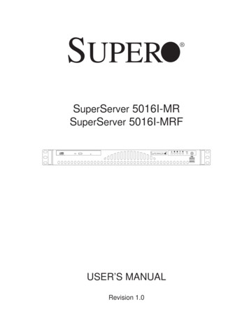
SuperServer E200-9B User's Manual1.5 Motherboard LayoutBelow is a layout of the X11SBA-LN4F with jumper, connector and LED locations shown. Seethe table on the following page for descriptions. For detailed descriptions, pinout informationand jumper settings, refer to Chapter 4.USB0/1 IPMI LANVGAUSB2/3 (3.0)JPG1LAN2/4AUDIO FPHDMI/DPLAN1/3VGAAUDIO FPJPAC1JPG1JPAC1LAN2LAN4JIPMB1SRW1USB0/1IPMI LANLAN1LAN3JIPMB1FAN1BAR CODEDESIGNED IN USALEDBMC(install first)SRW2SODIMM1(1.35V only)mSATA/mini PCIESODIMM2(1.35V only)JGP1JPW2JSTBY1JSTBY1BIOS LICENSEUSB4BT1JSD1JF1PWR RST X 2JPW21JI2C2 ED2X11SBACPU SLOT1 PCI-E 2.0 X1 (IN X8)LEDBMCHDMI/DPUSB2/3(3.0)NIC NIC HDD PWR X NMI21 LED LEDJPW1JBT1JSATA1JF1LED3JF1 USB5/6 USB7/8 JSD1JWD1I-SATA0 USB4 I-SATA1 JTPM1 JD2JSATA1Figure 1-2. Motherboard Layout10JPW1JBT1BT1
Chapter 1: IntroductionJumperDescriptionDefault SettingJBT1CMOS ClearOpen (Normal); Short: Clear CMOSJI2C1/JI2C2SMB to PCI-E Slots Enable/DisablePins 1-2 (Enabled)JPAC1Audio EnablePins 1-2 (Enabled)JPG1VGA Enable/DisablePins 1-2 (Enabled)JPME2Manufacturing ModePins 1-2 (Normal)JWD1Watch Dog TimerPins 1-2 (Reset)LEDDescriptionStatusLED1CPU Power LEDBlue On: Power OnLED2Standby Power LEDGreen On: Power OnLED3Main Power LEDGreen On: Power OnLEDBMCBMC Heartbeat LEDBlinking Green: BMC NormalConnectorDescriptionAUDIO FPAudio Front Panel HeaderBT1Onboard BatteryCOM1/COM2Serial COM HeadersFAN1/FAN2System/CPU Fan HeadersHDMI/DPBack Panel High Definition Multimedia Interface/DisplayPortIPMI LANIPMI Dedicated LAN PortI-SATA0/I-SATA1Intel PCH SATA 3.0 Ports (I-SATA1 supports SuperDOM)JGP1General Purpose I/O HeadersJD2External Speaker HeaderJF1Front Panel Control HeaderJIPMB14-pin BMC External I2C HeaderJL1Chassis Intrusion HeaderJPW124-pin ATX Power ConnectorJPW24-pin 12V Power Connector (Optional Power Source when the 24-pin ATX power is notin use)JSATA14-pin Connector for HDD use (to provide power from the motherboard to onboarddevices)JSD1SATA DOM Power ConnectorJSTBY1Standby Power HeaderJTPM1Trusted Platform Module/Port 80 ConnectorLAN1 LAN4LAN (RJ45) Ports (-F with dual LAN only)mSATA/miniPCI-EmSATA/mini-PCI-E ConnectorSLOT1CPU Slot PCI-E 2.0 X1 (IN X8)SRW1/SRW2mSATA Holding ScrewsUSB0/1Back panel Universal Serial Bus (USB) 2.0 PortsUSB2/3Back Panel USB 3.0 PortsUSB4USB Type A HeaderUSB5/6, USB7/8Front Panel USB 2.0 Headers11
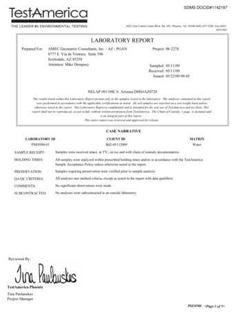
SuperServer E200-9B User's ManualNotes: " " indicates the location of Pin 1. Jumpers/LED indicators not indicated are used for testing only. See Chapter 3 for detailed information on connectors, jumpers, and I/O portsSystem Block DiagramHDMI connectorIntel BRASWELL-DDDI04 Cores/8 Threads2.4G/ 2M L2 CacheDP connectorFor booting up, should pop in Channel 0DUAL CHANNELDDI2Non-ECC-SODIMM0DDR3L 1600 MHzFLASHSPI 128MbSPIRear USB3.0 connector (USB 1)Rear USB3.0 connector (USB 2)Rear USB2.0 connector (USB 1)Rear USB2.0 connector (USB 2)USB HEADERUSB HEADERUSB s480Mb/sUSB 2.0 [1]480Mb/sUSB 2.0 [4]PCIE [0]PCIE [1]PCIE [3]USB 2.0 [C2-2]MUXSATA5.0GT/sFRONT AUDIOHEADERPCIe Gen2 x 15.0GT/sPCIe Gen2 x 15.0GT/s6Gb/sSATA 6Gb/sPCIe X8 SLOTGLAN1INTEL I210BMCAST 2400SATA [0]5.0GT/s608GPSATA [1]RJ45VGARTL 8211E(LN4F/F)IPMIRJ45PCIe Gen2 x 1PericomI-SATA0I-SATA1PCIe Gen2 x 1USB 2.0 [C2-1]PCIE [2]mSATAREALTEKALC888S-VD2-GRUSB 2.0 [0]480Mb/sUSB 2.0 [C1-3]USB 2.0 [C2-3]USB 2.0 [C1-4]USB 2.0 [C2-4]USB 2.0 [C1-1]High DefinitionUSB 2.0 [2]USB 3.0 [1]USB 2.0 [3]USB 3.0 [2]5.0Gb/sGL854G480Mb/sMAX. 8G SO-DIMM SUPPORTEDFST SPILPCDebug Header/TPM HEADERNon-ECC-SODIMM1GLAN2INTEL I210RJ45(LN4F/F)GLAN3INTEL I210RJ45(LN4F)GLAN4INTEL I210RJ45(LN4F)Mini PCIeFigure 1-3. Intel N3700 SoC Chipset: System Block DiagramNote: This is a general block diagram and may not exactly represent the features on yourmotherboard. See the System Specifications appendix for the actual specifications of yourmotherboard.12
Chapter 1: Introduction1-6 Server Installation and SetupThe server is shipped with the onboard processor and the motherboard installed in thechassis. Several steps are necessary to begin using your server. You must add memory,mount the hard disk drive, and mount the system in place.Unpacking the SystemInspect the box in which the system was shipped and note if it was damaged. If the serveritself shows damage, file a damage claim with the carrier.Warnings and Precautions Use a regulating uninterruptible power supply (UPS) to protect the server from powersurges, voltage spikes and to keep your system operating in case of a power failure. Review the electrical and general safety precautions in Appendix B.Adding Components to your System Memory: If your system is not already fully integrated with system memory, refer to Chapter2 for details on compatible types of memory and the installation procedure. Drives and Storage: To add storage capabilities to your server, see Chapter 2.Input/Output: See Chapter 3 for I/O ports and connect them as needed.Software: See Chapter 4 for description and procedures for installing software, includingdrivers and monitoring programs.13
SuperServer E200-9B User's ManualInstalling Mounting BracketsThe chassis includes mounting brackets that allow it to be mounted in any convenient spacein the work environment.1. Choose the desired bracket mounting configuration. Note that the backets can beinstalled in two orientations--with the brackets extending out from the chassis (as Figure1-2), or he brackets under the chassis (as Figure 1-3).Figure 1-2. Installing Mounting Brackets(Brackets extending out from the chassis)2. Secure the brackets to the surface where you want the server to be mounted.3. Install the server, using four screws through the holes in the brackets and screw theminto the chassis.Figure 1-3. Installed Mounting Brackets(Brackets under the chassis)14
Chapter 2Maintenance and Component InstallationChapter 2Maintenance and Component InstallationThis chapter provides instructions on installing and replacing main system components. Toprevent compatibility issues, only use components that match the specifications and/or partnumbers given.Installation or replacement of most components require that power first be removed from thesystem. Please follow the procedures given in each section.2.1 Removing PowerUse the following procedure to ensure that power has been removed from the system. Thisstep is necessary when removing or installing non hot-swap components or when replacinga non-redundant power supply.1. Use the operating system to power down the system.2. After the system has completely shut-down, disconnect the AC adapter power cord fromthe power source.3. Disconnect the power cord from the chassis.15
SuperServer E200-9B User's Manual2.2 Accessing the SystemThe SC101S features a removable top cover to access to the inside of the chassis.2Cover HookCover Hook3Figure 2-1. Removing the Chassis CoverRemoving the Top Cover1. Power down the system as described in section 3.1.2. Remove the two side screws that hold the chassis cover in place and set these aside forlater use.3. Slide the cover sideways as illlustrated above to release the front and rear cover hooksfrom the chassis.4. Lift the cover up and off the chassis.Caution: Except for short periods of time, do not operate the server without the cover inplace. The chassis cover must be in place to allow proper airflow and prevent overheating.16
Chapter 2Maintenance and Component Installation2.3 Motherboard ComponentsProcessorThe E200-9B features an embedded Intel N3700 SoC processor.Memory SupportThe motherboard supports up to 8 GB of DDR3L Dual Non-ECC SO-DIMM of speeds up to1600MHz in two low-profile slots.Channel0Channel1SoC Memory 066MHz1600MHz1600MHz1600MHzCheck the Supermicro website for a list of memory modules that have been validated. Usememory modules of the same type, speed and frequency.17
SuperServer E200-9B User's ManualInstalling MemoryInsert one or two SO-DIMMs into the memory slots, starting with JDIMM1 then JDIMM2.Caution: Exercise extreme care when installing or removing DIMM modules to preventdamage.Installing a SO-DIMM Module into a Horizontal Socket1. Align the receptive point on the bottom of the SO-DIMM module against the key on thememory socket. Note the notches on the side of the SO-DIMM module and those on thesocket to avoid causing damage.SO-DIMM MemoryModuleReceptive Pointon the ModuleSocket KeyMemory Module Socket2. Line up the bottom of the SO-DIMM memory module with the edge of the horizontalsocket.3. Once they are lined up, push the memory module into the memory socket until themodule is securely seated in the socket.18
Chapter 2Maintenance and Component InstallationExpansion CardThis server offers a mini-PCIe slot with mSATA support.Half-size Cardwith BracketFull-size CardFigure 2-2. Installing a Mini-PCIe Expansion CardInstalling a mSATA Mini-PCIe Expansion Card1. Access the motherboard and find the mSATA/mini PCIe connector.2. Gently insert mini-PCIe Card into the connector. For a half size card, obtain the optionalbracket, P/N MCP-120-00089-0N, to support your card.3. Use screws to secure the mini-PCIe Card to SRW1 standoff.19
SuperServer E200-9B User's ManualMotherboard BatteryThe motherboard uses non-volatile memory to retain system information when system poweris removed. This memory is powered by a lithium battery residing on the motherboard.LITHIUM BATTERYBATTERY HOLDERFigure 2-3. Installing the Onboard BatteryReplacing the Battery1. Remove power from the system as described in section 3.1.2. Push aside the small clamp that covers the edge of the battery. When the battery isreleased, lift it out of the holder.3. To insert a new battery, slide one edge under the lip of the holder with the positive ( )side facing up. Then push the other side down until the clamp snaps over it.Note: Handle used batteries carefully. Do not damage the battery in any way; a damagedbattery may release hazardous materials into the environment. Do not discard a used batteryin the garbage or a public landfill. Please comply with the regulations of your local hazardouswaste management agency to dispose of your used battery properly.Warning: There is a danger of explosion if the onboard battery is installed upside down (whichreverses its polarities). This battery must be replaced only with the same or an equivalenttype recommended by the manufacturer (CR2032).20
Chapter 2Maintenance and Component Installation2-4 Chassis ComponentsInstalling the Hard DriveThe SC101S can accommodate a single fixed 2.5" hard drive of 15 mm thickness. It is installedto a mounting tray inside the chassis. Use an enterprise quality drive.Figure 2-4. Installing the Hard DriveInstalling the Hard DriveThe motherboard should be installed before installing the hard drive.1. Make sure there is no power to the system as described in section 3-1 and remove thechassis cover.2. Remove the two screws securing the hard drive tray to the support bracket and set themaside for later use. Lift the tray out.3. Place the hard drive into the tray and secure it to the tray with the screws provided withhard drive.4. Return the hard drive tray assembly into the chassis, aligning the tabs of the tray withthe slots in the chassis. Secure the tray to the chassis support bracket with the screwspreviously set aside.5. Attach the cable SATA connector and to the motherboard connector. This cable carriesboth the SATA sginal and the SATA power.6. Reinstall the chassis cover and power up the system.21
SuperServer E200-9B User's ManualSystem CoolingThe SC101S includes one 4-cm fan. The chassis also supports an additional optional 4-cmfan.Replacing the System Fan1. Power down the system as described in section 3-1 and remove the AC power cord andthe chassis cover.2. Remove the failed fan power cable from motherboard.3. Remove the screws securing the fan to the chassis wall and set these aside for lateruse.4. Lift the fan out of the chassis.5. Align the replacement fan with the holes in the wall of the chassis.6. Secure the fan to the chassis wall using the screws previously set aside.7. Reconnect the fan cable to motherboard.8. Reinstall the chassis top cover, reconnect the AC power cord and power up the system.Figure 2-5. System Fan22
Chapter 3Motherboard ConnectionsChapter 3Motherboard ConnectionsThis section describes the connections on the X11SBA-LN4F motherboard and providespinout definitions. Note that depending on how the system is configured, not all connectionsare required. The LEDs on the motherboard are also described here. A motherboard layoutindicating component locations may be found in Chapter 1.Please review the Safety Precautions in Appendix A before installing or removing components.3.1 Power ConnectionsMain ATX Power Supply ConnectorThe primary power supply connector (JPW1) meets the ATX SSI EPS 24-pin specification.ATX Power 24-pin ConnectorPin DefinitionsPin#DefinitionPin#Definition13 3.3V1 3.3V14NC2 3.3V15Ground3Ground16PS ON4 5V17Ground5Ground18Ground6 5V19Ground7Ground20Res (NC)8PWR OK21 5V95VSB22 5V10 12V23 5V11 12V24Ground12 3.3V23
SuperServer E200-9B User's Manual4-pin 12V Power ConnectorJPW2 is the 12V DC power connector that provides alternative single power source for specialenclosure when the 24-pin ATX power is not in use. 12V 4-pin PowerPin DefinitionsPin#Definition1-2Ground3-4 12V3142JPW2 Pin LayoutRequired ConnectionNote 1: The 12V DC input is limited to 12A by design. It provides up to 144W power input tothe motherboard. Please keep onboard power use within the power limits specified above.Over-current DC power use may cause damage to the motherboard.Note 2: Do not use the 4-pin DC power at JPW2 when the 24-pin ATX Power at JPW1 isconnected to the power supply. Do not plug in both JPW1 and JPW2 at the same time.3.2 Headers and ConnectorsFan HeadersThere are two 4-pin fan headers on the motherboard. Although pins 1-3 of the fan headersare backward compatible with the traditional 3-pin fans, we recommend you use 4-pin fans totake advantage of the fan speed control via Pulse Width Modulation through the BMC. Thisallows the fan speeds to be automatically adjusted based on the motherboard temperature.Fan HeaderPin DefinitionsPin#Definition1Ground (Black)2 12V (Red)3Tachometer4PWM ControlExternal SpeakerThe JD2 header is for the external speaker. If you wish to use an external speaker, connectits cable to pins 1-4.External Speaker ConnectorPin DefinitionsPin SettingDefinitionPins 1-4Speaker24
Chapter 3Motherboard ConnectionsGPIO HeadersThe JGP1 (General Purpose Input/Output) header is located near the SATA connectors onthe motherboard. The JGP1 header is a general-purpose I/O expander on a pin header fromIntel SoC. See the table below for pin definitions. Refer to the board layout below for thelocations of the headers.GPIO HeaderPin DefinitionsPin#DefinitionCFIO NameCFG0CFG113V3 STBYN/AN/AN/A3GP0I2C0 SCL0xFED854280xFED8542C5GP1I2C0 SDA0xFED854080xFED8540C7GP2I2C1 SCL0xFED854180xFED8541C9GP3I2C1 SDA0xFED854000xFED854042GNDN/AN/AN/A4GP4I2C2 SCL0xFED854300xFED854346GP5I2C2 SDA0xFED854100xFED854148GP6I2C3 SCL0xFED854380xFED8543C10GP7I2C3 SDA0xFED854200xFED8542421019GPIO Header Pin LayoutNote: The "I2C# SCL/SDA" are pin names of Intel N3700 SoC GPIO.Disk-
support@supermicro.com (Technical Support) Website: www.supermicro.com Europe Address: Super Micro Computer B.V. Het Sterrenbeeld 28, 5215 ML 's-Hertogenbosch, The Netherlands Tel: 31 (0) 73-6400390 Fax: 31 (0) 73-6416525 Email: sales@supermicro.nl (General Information) support@supermicro.nl (Technical Support) rma@supermicro.nl (Customer .