Transcription
SUPERH8DGiH8DGi-FH8DG6H8DG6-FUSER’S MANUALRevision 1.0b
The information in this User’s Manual has been carefully reviewed and is believed to be accurate.The vendor assumes no responsibility for any inaccuracies that may be contained in this document,makes no commitment to update or to keep current the information in this manual, or to notify anyperson or organization of the updates. Please Note: For the most up-to-date version of thismanual, please see our web site at www.supermicro.com.Super Micro Computer, Inc. ("Supermicro") reserves the right to make changes to the productdescribed in this manual at any time and without notice. This product, including software anddocumentation, is the property of Supermicro and/or its licensors, and is supplied only under alicense. Any use or reproduction of this product is not allowed, except as expressly permitted bythe terms of said license.IN NO EVENT WILL SUPERMICRO BE LIABLE FOR DIRECT, INDIRECT, SPECIAL, INCIDENTAL,SPECULATIVE OR CONSEQUENTIAL DAMAGES ARISING FROM THE USE OR INABILITY TOUSE THIS PRODUCT OR DOCUMENTATION, EVEN IF ADVISED OF THE POSSIBILITY OFSUCH DAMAGES. IN PARTICULAR, SUPERMICRO SHALL NOT HAVE LIABILITY FOR ANYHARDWARE, SOFTWARE, OR DATA STORED OR USED WITH THE PRODUCT, INCLUDING THECOSTS OF REPAIRING, REPLACING, INTEGRATING, INSTALLING OR RECOVERING SUCHHARDWARE, SOFTWARE, OR DATA.Any disputes arising between manufacturer and customer shall be governed by the laws of SantaClara County in the State of California, USA. The State of California, County of Santa Clara shallbe the exclusive venue for the resolution of any such disputes. Super Micro's total liability for allclaims will not exceed the price paid for the hardware product.FCC Statement: This equipment has been tested and found to comply with the limits for a ClassA digital device pursuant to Part 15 of the FCC Rules. These limits are designed to providereasonable protection against harmful interference when the equipment is operated in a commercialenvironment. This equipment generates, uses, and can radiate radio frequency energy and, if notinstalled and used in accordance with the manufacturer’s instruction manual, may cause harmfulinterference with radio communications. Operation of this equipment in a residential area is likelyto cause harmful interference, in which case you will be required to correct the interference at yourown expense.California Best Management Practices Regulations for Perchlorate Materials: This Perchloratewarning applies only to products containing CR (Manganese Dioxide) Lithium coin cells. “PerchlorateMaterial-special handling may apply. See NG: Handling of lead solder materials used in thisproduct may expose you to lead, a chemical known tothe State of California to cause birth defects and otherreproductive harm.Manual Revision 1.0bRelease Date: March 28, 2011Unless you request and receive written permission from SUPER MICRO COMPUTER, you may notcopy any part of this document.Information in this document is subject to change without notice. Other products and companiesreferred to herein are trademarks or registered trademarks of their respective companies or markholders.Copyright 2011 by SUPER MICRO COMPUTER INC.All rights reserved.Printed in the United States of America
PrefacePrefaceAbout This ManualThis manual is written for system integrators, PC technicians andknowledgeable PC users. It provides information for the installation and use of theH8DG6/i(-F) serverboard.The H8DG6/i(-F) serverboard is based on the AMD Dual SR5690 and one SP5100chipset and supports two AMD Socket G34 type processor with up to64 GB of ECC/Non-ECC UDIMM or up to 256 GB of ECC RDIMM. This boardseries includes the following serverboards and characteristics:Embeded IPMIOnbard SAS2H8DG6YesH8DGiH8DG6-FYesH8DGi-FYesYesPlease refer to the motherboard specifications pages on our web site for updates onsupported processors (http://www.supermicro.com/aplus/). This product is intendedto be professionally installed.Manual OrganizationChapter 1 includes a checklist of what should be included in your motherboardbox, describes the features, specifications and performance of the motherboardand provides detailed information about the chipset.Chapter 2 begins with instructions on handling static-sensitive devices. Read thischapter when installing the processor(s) and memory modules and when installingthe motherboard in a chassis. Also refer to this chapter to connect the hard diskdrives, the various ports, and the power and reset buttons and the system LEDs.If you encounter any problems, see Chapter 3, which describes troubleshootingprocedures for the video, the memory and the setup configuration stored in CMOS.For quick reference, a general FAQ (Frequently Asked Questions) section isprovided. Instructions are also included for contacting technical support. In addition,you can visit our web site for more detailed information.Chapter 4 includes an introduction to BIOS and provides detailed information onrunning the CMOS Setup utility.Appendix A provides BIOS Error Beep Code Messages.Appendix B lists BIOS POST Checkpoint Codes.iii
H8DG6/i(-F) Serverboard User’s ManualNotesiv
Table of ContentsTable of ContentsChapter 1 Introduction1-1Overview . 1Checklist . 11-2Contacting Supermicro . 21-3Chipset Overview . 10H8DG6/i(-F) Quick Reference . 5AMD SR5690/SP5100 Processor . 10HyperTransport Technology . 101-4PC Health Monitoring . 101-5Power Configuration Settings.111-6Power Supply . 121-7Super I/O . 13Chapter 2 Installation2-1Static-Sensitive Devices . 1Precautions . 1Unpacking . 12-2Processor and Heatsink Installation. 22-3Mounting the Motherboard into a Chassis . 42-4Installing Memory . 42-5PCI Expansion Cards . 72-6I/O Port and Control Panel Connections . 82-7Connector Definitions . 9DIMM Module Population Configuration . 6Front Control Panel . 8Power Connectors . 9Power LED Connector . 9HDD/FP UID Switch . 9Overheat (OH)/Fan Fail/PWR Fail/UID LED . 10Power Fail LED . 10Reset Connector . 10Power Button . 10Serial Ports .11Fan Headers.11Power LED/Speaker .11Chassis Intrusion .11Overheat LED. 12v
H8DG6/i(-F) Serverboard User’s ManualPower I2C. 12Trusted Platform Module Header . 12JSMB1 (H8DG6/i-F only) . 12Wake-On-LAN . 13LAN1/2 (Ethernet Ports) . 13ATX PS/2 Keyboard and PS/2 Mouse Ports . 13DOM Power Connector . 13SGPIO . 14Unit Identifier Button. 14Universal Serial Bus Ports . 14USB Headers . 14Video Connector . 15JIBTN1 Header(only on H8DG6(-F)). 152-8Jumper Settings . 16Explanation of Jumpers . 16CMOS Clear . 16LAN Enable/Disable . 17SAS Enable/Disable . 17VGA Enable/Disable . 17I2C to PCI-Express Slot . 17BMC Jumper . 17Watch Dog Enable/Disable . 18USB Wake-Up . 182-9Onboard Indicators. 18LAN1/LAN2 LEDs . 18Dedicated IPMI LAN LEDs (H8DG6/i-F only) . 18BMC Heartbeat LED . 19Power LED . 19SAS2008 Heartbeat LED . 19UID LED (LE1) . 192-10SAS and SATA Drive Connections . 20SATA Ports . 20SAS Ports (H8DG6(-F) Only) . 202-11Enabling SATA RAID . 21Serial ATA (SATA). 21Installing the OS/SATA Driver . 21Building a Driver Diskette . 21Enabling SATA RAID in the BIOS . 22Using the Adaptec RAID Utility . 23vi
Table of ContentsInstalling the RAID Driver During OS Installation . 232-12Installing Drivers. 24Supero Doctor III . 25Chapter 3 Troubleshooting3-1Troubleshooting Procedures . 1Before Power On . 1No Power . 1No Video . 2Memory Errors . 2Losing the System’s Setup Configuration . 23-2Technical Support Procedures . 33-3Frequently Asked Questions . 33-4Returning Merchandise for Service. 4Chapter 4 BIOS4-1Introduction. 14-2Main Menu . 24-3Advanced Settings Menu . 24-3Security Menu . 144-4Boot Menu . 144-5Exit Menu . 15Appendix A BIOS Error Beep CodesAppendix B BIOS POST Checkpoint CodesB-1Uncompressed Initialization Codes . 1B-2Bootblock Recovery Codes . 2B-3Uncompressed Initialization Codes . 3vii
H8DG6/i(-F) Serverboard User’s ManualNotesviii
Chapter 1: IntroductionChapter 1Introduction1-1OverviewChecklistCongratulations on purchasing your computer motherboard from an acknowledgedleader in the industry. Supermicro boards are designed with the utmost attention todetail to provide you with the highest standards in quality and performance.Please check that the following items have all been included with your motherboard.If anything listed here is damaged or missing, contact your retailer. One (1) H8DG6/i(-F) serverboard One (1) I/O shield (MCP-260-00027-0N) One (1) 9-pin serial port cable (CBL-0010L) One (1) 15.7-inch USB 2.0 2-Port with Key cable (CBL-0083L) Two (2) 50-cm I-Pass to four SATA PBF cables (CBL-0097L-02) (for H8DG6and H8DG6-F only) Four (4) 2ft. Amphenol, SATA cable (CBL-0044L) (Six for H8DGi or H8DGi-F) One (1) CD containing drivers and utilities1-1
H8DG6/i(-F) Serverboard User’s Manual1-2Contacting SupermicroHeadquartersAddress:Super Micro Computer, Inc.980 Rock Ave.San Jose, CA 95131 U.S.A.Tel: 1 (408) 503-8000Fax: 1 (408) 503-8008Email:marketing@supermicro.com (General Information)support@supermicro.com (Technical Support)Web Site:www.supermicro.comEuropeAddress:Super Micro Computer B.V.Het Sterrenbeeld 28, 5215 ML's-Hertogenbosch, The NetherlandsTel: 31 (0) 73-6400390Fax: 31 (0) 73-6416525Email:sales@supermicro.nl (General Information)support@supermicro.nl (Technical Support)rma@supermicro.nl (Customer Support)Asia-PacificAddress:Super Micro Computer, Inc.4F, No. 232-1, Liancheng Rd.Chung-Ho 235, Taipei CountyTaiwan, R.O.C.Tel: 886-(2) 8226-3990Fax: 886-(2) 8226-3991Web Site:www.supermicro.com.twTechnical 228-1366, ext.132 or 1391-2
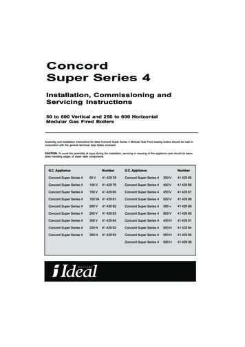
Chapter 1: IntroductionFigure 1-1. H8DG6/i(-F) Image1-3
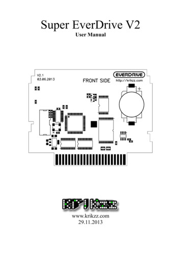
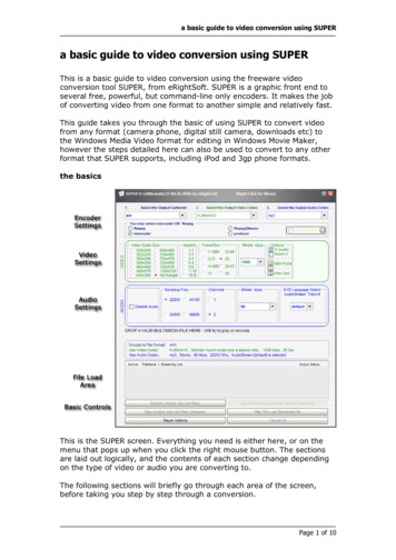
H8DG6/i(-F) Serverboard User’s ManualFigure 1-2. H8DG6/i(-F) Motherboard Layout(not drawn to KB/MOUSEVGAJPL1UIDUSB0/1IPMI 1-DIMM4AP1-DIMM4BSLOT6 PCI-E 2.0 X16SLOT5 PCI-E 2.0 X4 (IN X8)SLOT4 PCI-E 2.0 X16SLOT3 PCI-E 2.0 X8T-SGPIO1 T-SGPIO2SLOT2 PCI-E 2.0 X16USB4/5SLOT1 PCI-E 2.0 X4 (IN A5LEDS1JPW2USB7JTPM1SAS 4 7SAS 0 es:Jumpers not indicated are for test purposes only.Not all ports, jumpers or LED Indicators are available on all serverboards.1-4
Chapter 1: IntroductionH8DG6/i(-F) Quick ReferenceJumperDescriptionDefault SettingJBT1CMOS Clear(See Section 2-7)JI2C1/JI2C2I2C to PCI-E Slot Enable/DisableBoth Closed (Enabled)JPB1BMC Enable/DisablePins 1-2 (Enabled)JPG1VGA Enable/DisablePins 1-2 (Enabled)JPL1LAN 1 Enable/DisablePins 1-2 (Enabled)JPS1SAS Controller Enable/DisablePins 1-2 (Enabled)JWD1Watch DogPins 1-2 (Reset)LEDDescriptionLAN PortsLEDs for the LAN Ethernet portsDedicated IPMI LANLEDs for the dedicated IPMI LAN Ethernet port (H8DGi/6-F only)DP1LED for BMC HeartbeatDP3LED for Serverboard Power-OnLE1LED for UID ButtonLEDS1SAS2008 Heartbeat LED1-5
H8DG6/i(-F) Serverboard User’s ManualConnectorDescriptionCOM1/COM2COM1 Serial Port/HeaderFAN 1-8Chassis/CPU Fan HeadersIPMI LANDedicated IPMI LAN Port (H8DGi/6-F only)JD1Speaker HeaderJF1Front Panel ConnectorJIBTN1RAIDKey for RAID 5 SAS support (optional for H8DG6(-F))JL1Chassis Intruder HeaderJOH1Overheat Warning HeaderJPI2C1Power I2C HeaderJPW124-pin Main ATX Power ConnectorJPW2/3 12V 8-pin CPU Power ConnectorsJTPM1Trusted Platform Module HeaderJSMB1System Management Bus Header (SMBus)JWF1SATA DOM (Disk On Module) PWRJWOL1Wake-On-LAN HeaderLAN1/2Gigabit Ethernet (RJ45) PortsPS2 Mouse/KeyboardPS2 Mouse/Keyboard connectorsSAS0 3, SAS4 7SAS Ports (H8DG6(-F) only)SATA0 SATA5SATA PortsT-SGPIO-1/T-SGPIO-2Serial General Purpose Input/Output Header for SATAUSB0/1, USB2/3, USB4/5, USB6/7Universal Serial Bus (USB) Ports, Headers and Type-A PortVGAVGA Connector1-6
Chapter 1: IntroductionMotherboard FeaturesCPU Dual AMD Opteron 6100 series (AMD Socket G34 type) processorNote: Refer to our web site for details on supported processors.Memory Sixteen (16) four channel DIMM slots support up to64 GB of ECC/Non-ECC UDIMM or up to 256 GB of ECC RDIMMDDR3-1333/1066 in 1 GB, 2 GB, 4 GB, 8 GB or 16 GB sizes of 1.5V or 1.35Vvoltages.Note: Refer to Section 2-4 before installing memory and our web site for recommended DIMMs.Chipset Dual AMD SR5690 chipset and one SP5100 Southbridge chipsetExpansion Slots Three (3) PCI-Express x16 Gen. 2One (1) PCI-Express x8 Gen. 2Two (2) PCI-Express x4 (in x8 slot) Gen. 2BIOS 16 Mb AMIBIOS SPI Flash ROMDMI 2.3, PCI 2.2, ACPI 1.0 (ACPI 2.0 is BIOS supported), SMBIOS 2.3, RealTime Clock Wakeup, Plug and Play (PnP), BIOS resume hot keys, HardwareBIOS Virus ProtectionPC Health Monitoring Onboard voltage monitorsFan status monitor with firmware/software on/off and speed controlWatch DogEnvironmental temperature monitoring via BIOSPower-up mode control for recovery from AC power lossSystem resource alert (via included utility program)Auto-switching voltage regulator for the CPU coreCPU thermal trip supportI2C temperature sensing logicChipkill Support1-7
H8DG6/i(-F) Serverboard User’s ManualACPI Features Microsoft OnNowSlow blinking LED for suspend state indicatorBIOS support for USB keyboardWake-On-LAN (WOL)Onboard I/O Six (6) SATA ports supported by an on-chip SATA controller (RAID 0, 1, 10supported) Eight (8) SAS ports supported by an LSI 2008 SAS2 controller (RAID 0, 1, 10supported; Raid 5 Optional) (H8DG6(-F) only) Eight (8) USB (Universal Serial Bus 2.0) ports (2x rear, 4x header,2x type A) Two (2) LAN ports supported by two onboard Intel 82576 Ethernet controllersfor 10/100/1000Base-T One (1) dedicated IPMI LAN port (H8DG6/i-F only) One (1) VGA port supported by an onboard Matrox G200 graphics controller(with 16 MB DDR2 memory)Two COM Ports (one external serial port, one Fast UART 16550 port)Other Onboard power LEDChassis intrusion detectionCD Utilities BIOS flash upgrade utilitySuper Doctor IIIIPMI 1.5 / 2.0Dimensions Extended-ATX form: 12" x 13" (305 x 330 mm)1-8
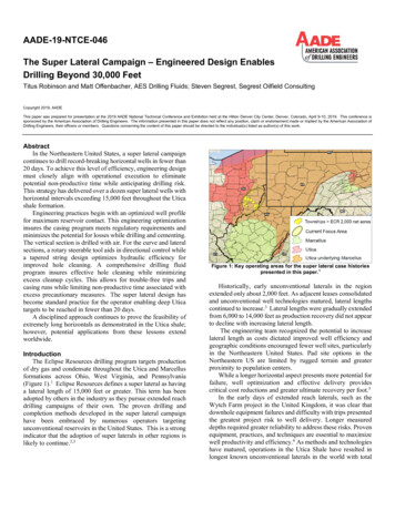
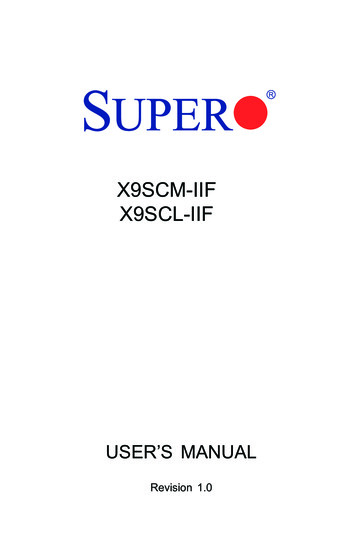
Chapter 1: IntroductionFigure 1-3. AMD Dual SR5690 and one SP5100 Chipset:System Block DiagramNote: This is a general block diagram and may not exactly representthe features on your motherboard. See the previous pages for theactual specifications of your motherboard.VRMVRMDDR31333/10668x DIMMG34-SOCKET #2LANIntel 82576AMDSR5690#2HT Link16/16-2.6GHzSLOT#1PCIE (X4)8x DIMMG34-SOCKET #1HT Link16/16-2.6GHzSLOT#2PCIE (X16)DDR31333/1066HT LinkPCIE (X8)LSISAS2 2008PCIE (X4)SLOT#5PCIE (X4)PCIE (X8)SLOT#3PCIE (X8)PCIE (X16)SLOT#6PCIE (X16)PCIE (x4)AMDSR5690#1SLOT#4PCIE (X16)SATASATA PORT X6VGAWinbondWPCM450AMDSP5100USBUSB PORT X8LPC BUSH/W MONITORW83795LPC SIOW83627DHG-PFANCONN. (8)KEYBOARD/MOUSE1-9FWH
H8DG6/i(-F) Serverboard User’s Manual1-3Chipset OverviewThe H8DG6/i(-F) serverboard is based on the AMD Dual SR5690 and one SP5100chipset. This chipset functions as a Media and Communications Processor (MCP).Controllers for the system memory are integrated directly into AMD Opteronprocessors.AMD SR5690/SP5100 ProcessorThe AMD Dual SR5690 and one SP5100 are each a single-chip, high-performanceHyperTransport peripheral controller. It includes a 42-lane PCI Express interface, anAMD Opteron 16-bit Hyper Transport interface link, a six-port Serial ATA interfaceand an eight-port USB 2.0 interface. This hub connects directly to the CPU.HyperTransport TechnologyHyperTransport technology is a high-speed, low latency point to point link that wasdesigned to increase the communication speed by a factor of up to 48x betweenintegrated circuits. This is done partly by reducing the number of buses in thechipset to reduce bottlenecks and by enabling a more efficient use of memoryin multi-processor systems. The end result is a significant increase in bandwidthwithin the chipset.1-4PC Health MonitoringThis section describes the PC health monitoring features of the H8DG6/i(-F)serverboard. The serverboard has an onboard System Hardware Monitor chip thatsupports PC health monitoring.Onboard Voltage MonitorsThe onboard voltage monitor will continuously scan crucial voltage levels. Oncea voltage becomes unstable, it will give a warning or send an error message tothe screen. Users can adjust the voltage thresholds to define the sensitivity of thevoltage monitor. Real time readings of these voltage levels are all displayed inBIOS.Fan Status Monitor with Firmware/Software Speed ControlThe PC health monitor can check the RPM status of the cooling fans. The onboardfans are controlled by thermal management via BIOS.1-10
Chapter 1: IntroductionCPU Overheat/Fan Fail LED and ControlThis feature is available when the user enables the CPU overheat/Fan Fail warningfunction in the BIOS. This allows the user to define an overheat temperature. Whenthis temperature is exceeded or when a fan failure occurs, the Overheat/Fan Failwarning LED is triggered.Auto-Switching Voltage Regulator for the CPU CoreThe 6-phase-switching voltage regulator for the CPU core can support up toAMD Opteron 6100 series processors and auto-sense voltage IDs ranging from 0.8V to 1.55V. This will allow the regulator to run cooler and thus make the systemmore stable.1-5Power Configuration SettingsThis section describes the features of your motherboard that deal with power andpower settings.Microsoft OnNowThe OnNow design initiative is a comprehensive, system-wide approach to systemand device power control. OnNow is a term for a PC that is always on but appearsto be off and responds immediately to user or other requests.Slow Blinking LED for Suspend-State IndicatorWhen the CPU goes into a suspend state, the chassis power LED will start blinkingto indicate that the CPU is in suspend mode. When the user presses any key, theCPU will wake-up and the LED will automatically stop blinking and remain on.BIOS Support for USB KeyboardIf a USB keyboard is the only keyboard in the system, it will function like a normalkeyboard during system boot-up.Note: To wake up the system from an S4 state by the USB keyboard/mouse, pleaseconnect the keyboard/mouse to USB port 0/1 at the rear I/O side.1-11
H8DG6/i(-F) Serverboard User’s ManualMain Switch Override MechanismThe power button can function as a system suspend button. When the userdepresses the power button, the system will enter a SoftOff state. The monitorwill be suspended and the hard drive will spin down. Depressing the power buttonagain will cause the whole system to wake-up. During the SoftOff state, the powersupply provides power to keep the required circuitry in the system alive. In case thesystem malfunctions and you want to turn off the power, just depress and hold thepower button for 4 seconds. The power will turn off and no power will be providedto the motherboard.Wake-On-LAN (WOL)Wake-On-LAN is defined as the ability of a management application to remotelypower up a computer that is powered off. Remote PC setup, up-dates and accesstracking can occur after hours and on weekends so that daily LAN traffic is keptto a minimum and users are not interrupted. The motherboard has a 3-pin header(WOL) to connect to the 3-pin header on a Network Interface Card (NIC) that hasWOL capability. Wake-On-LAN must be enabled in BIOS.1-6Power SupplyAs with all computer products, a stable power source is necessary for proper andreliable operation. It is even more important for processors that have high CPUclock rates.The H8DG6/i(-F) serverboard requires the use of proprietary power supplies. Pleaserefer to the pinout information for the power connectors in Section 7 of Chapter 2for detailed information on power requirements.In areas where noisy power transmission is present, you may choose to install aline filter to shield the computer from noise. It is recommended that you also installa power surge protector to help avoid problems caused by power surges.Warning: To prevent the possibility of explosion, do not use the wrong type ofonboard CMOS battery or install it upside down.1-12
Chapter 1: Introduction1-7Super I/OThe disk drive adapter functions of the Super I/O Winbond BMC chip includes adata separator, write pre-compensation circuitry, decode logic, data rate selection,a clock generator, drive interface control logic and interrupt and DMA logic. Thewide range of functions integrated onto the Super I/O greatly reduces the numberof components required for interfacing with floppy disk drives.The Super I/O provides two high-speed, 16550 compatible serial communicationports (UARTs), one of which supports serial infrared communication. Each UARTincludes a 16-byte send/receive FIFO, a programmable baud rate generator,complete modem control capability and a processor interrupt system. Both UARTsprovide legacy speed with baud rate of up to 115.2 Kbps as well as an advancedspeed with baud rates of 250 K, 500 K, or 1 Mb/s, which support higher speedmodems.The Super I/O provides functions that comply with ACPI (Advanced Configurationand Power Interface), which includes support of legacy and ACPI power managementthrough a SMI or SCI function pin. It also features auto power management to reducepower consumption.The IRQs, DMAs and I/O space resources of the Super I/O can be flexibly adjustedto meet ISA PnP requirements, which support ACPI and APM (Advanced PowerManagement).1-13
Chapter 2: InstallationChapter 2Installation2-1Static-Sensitive DevicesElectrostatic Discharge (ESD) can damage electronic components. To preventdamage to your system board, it is important to handle it very carefully. The followingmeasures are generally sufficient to protect your equipment from ESD.Precautions Use a grounded wrist strap designed to prevent static discharge.Touch a grounded metal object before removing the board from the antistaticbag.Handle the board by its edges only; do not touch its components, peripheralchips, memory modules or gold contacts.When handling chips or mo
support@supermicro.com (Technical Support) Web Site: www.supermicro.com Europe Address: Super Micro Computer B.V. Het Sterrenbeeld 28, 5215 ML 's-Hertogenbosch, The Netherlands Tel: 31 (0) 73-6400390 Fax: 31 (0) 73-6416525 Email: sales@supermicro.nl (General Information) support@supermicro.nl (Technical Support) rma@supermicro.nl (Customer .