Transcription
SuperServer E300-9A-4CE300-9A-8CUSER’S MANUALRevision 1.0
The information in this User’s Manual has been carefully reviewed and is believed to be accurate. The vendor assumesno responsibility for any inaccuracies that may be contained in this document, and makes no commitment to updateor to keep current the information in this manual, or to notify any person or organization of the updates. Please Note:For the most up-to-date version of this manual, please see our website at www.supermicro.com.Super Micro Computer, Inc. ("Supermicro") reserves the right to make changes to the product described in this manualat any time and without notice. This product, including software and documentation, is the property of Supermicro and/or its licensors, and is supplied only under a license. Any use or reproduction of this product is not allowed, exceptas expressly permitted by the terms of said license.IN NO EVENT WILL Super Micro Computer, Inc. BE LIABLE FOR DIRECT, INDIRECT, SPECIAL, INCIDENTAL,SPECULATIVE OR CONSEQUENTIAL DAMAGES ARISING FROM THE USE OR INABILITY TO USE THIS PRODUCTOR DOCUMENTATION, EVEN IF ADVISED OF THE POSSIBILITY OF SUCH DAMAGES. IN PARTICULAR, SUPERMICRO COMPUTER, INC. SHALL NOT HAVE LIABILITY FOR ANY HARDWARE, SOFTWARE, OR DATA STOREDOR USED WITH THE PRODUCT, INCLUDING THE COSTS OF REPAIRING, REPLACING, INTEGRATING,INSTALLING OR RECOVERING SUCH HARDWARE, SOFTWARE, OR DATA.Any disputes arising between manufacturer and customer shall be governed by the laws of Santa Clara County in theState of California, USA. The State of California, County of Santa Clara shall be the exclusive venue for the resolutionof any such disputes. Supermicro's total liability for all claims will not exceed the price paid for the hardware product.FCC Statement: This equipment has been tested and found to comply with the limits for a Class A digital devicepursuant to Part 15 of the FCC Rules. These limits are designed to provide reasonable protection against harmfulinterference when the equipment is operated in a commercial environment. This equipment generates, uses, and canradiate radio frequency energy and, if not installed and used in accordance with the manufacturer’s instruction manual,may cause harmful interference with radio communications. Operation of this equipment in a residential area is likelyto cause harmful interference, in which case you will be required to correct the interference at your own expense.California Best Management Practices Regulations for Perchlorate Materials: This Perchlorate warning applies onlyto products containing CR (Manganese Dioxide) Lithium coin cells. “Perchlorate Material-special handling may apply.See NING: This product can expose you to chemicals includinglead, known to the State of California to cause cancer and birthdefects or other reproductive harm. For more information, goto www.P65Warnings.ca.gov.The products sold by Supermicro are not intended for and will not be used in life support systems, medical equipment,nuclear facilities or systems, aircraft, aircraft devices, aircraft/emergency communication devices or other criticalsystems whose failure to perform be reasonably expected to result in significant injury or loss of life or catastrophicproperty damage. Accordingly, Supermicro disclaims any and all liability, and should buyer use or sell such productsfor use in such ultra-hazardous applications, it does so entirely at its own risk. Furthermore, buyer agrees to fullyindemnify, defend and hold Supermicro harmless for and against any and all claims, demands, actions, litigation, andproceedings of any kind arising out of or related to such ultra-hazardous use or sale.Manual Revision 1.0Release Date: July 06, 2018Unless you request and receive written permission from Super Micro Computer, Inc., you may not copy any part of thisdocument. Information in this document is subject to change without notice. Other products and companies referredto herein are trademarks or registered trademarks of their respective companies or mark holders.Copyright 2018 by Super Micro Computer, Inc.All rights reserved.Printed in the United States of America2
PrefacePrefaceAbout this ManualThis manual is written for professional system integrators and PC technicians. It providesinformation for the installation and use of the SuperServer E300-9A-4C/E300-9A-8C.Installation and maintenance should be performed by experienced technicians only.NotesFor your system to work properly, please follow the links below to download all necessarydrivers/utilities and the user’s manual for your server. Supermicro product manuals: http://www.supermicro.com/support/manuals/ Product drivers and utilities: ftp://ftp.supermicro.com Product safety info: http://www.supermicro.com/about/policies/safety information.cfmIf you have any questions, please contact our support team at:support@supermicro.comThis manual may be periodically updated without notice. Please check the Supermicro website(http://www.supermicro.com) for possible updates to the manual revision level.WarningsSpecial attention should be given to the following symbols used in this manual.Warning! Indicates important information given to prevent equipment/property damageor personal injury.Warning! Indicates high voltage may be encountered when performing a procedure.3
SuperServer E300-9A-4C/E300-9A-8C User's ManualContentsChapter 1 Introduction1.1 Overview.71.2 System Features.81.3 Chassis Features.9Front Features.9Rear Features.101.4 Motherboard Layout.11Quick Reference Table.12Chipset Block Diagram.131-5 Server Installation and Setup.14Unpacking the System.14Warnings and Precautions.14Adding Components to your System .14Installing Rack Mounting Brackets.15Chapter 2 Maintenance and Component Installation2.1 Removing Power.162.2 Accessing the System.172.3 Motherboard Components.18Processor.18Memory Support.18Memory Population Sequence.18Installing Memory.19Solid State Storage .20Mini-PCI-E mSATA.21M.2.21Motherboard Battery.222.4 Chassis Components.23Installing the Storage Drive .23Installing the Riser Card .24System Cooling.254
PrefaceChapter 3 Motherboard Connections3.1 Power Connections.263.2 Headers and Connectors.27Control Panel.303.3 Ports.323.4 Jumpers.34Explanation of Jumpers.343.5 LED Indicators.363.6 SATA Connections.39Chapter 4 Software4.1 Driver Installation.404.2 SuperDoctor 5.414.3 IPMI.42Chapter 5 BIOS5.1 Introduction.43Starting the Setup Utility.435.2 Main Setup.445.3 Advanced.465.4 Event Logs.725.5 IPMI.745.6 Security.775.7 Boot.825.8 Save & Exit.84Appendix A BIOS Error CodesAppendix B Standardized Warning Statements for DC SystemsAppendix C System Specifications5
SuperServer E300-9A-4C/E300-9A-8C User's ManualContacting SupermicroHeadquartersAddress:Super Micro Computer, Inc.980 Rock Ave.San Jose, CA 95131 U.S.A.Tel: 1 (408) 503-8000Fax: 1 (408) 503-8008Email:marketing@supermicro.com (General Information)support@supermicro.com (Technical per Micro Computer B.V.Het Sterrenbeeld 28, 5215 ML's-Hertogenbosch, The NetherlandsTel: 31 (0) 73-6400390Fax: 31 (0) 73-6416525Email:sales@supermicro.nl (General Information)support@supermicro.nl (Technical Support)rma@supermicro.nl (Customer ss:Super Micro Computer, Inc.3F, No. 150, Jian 1st Rd.Zhonghe Dist., New Taipei City 235Taiwan (R.O.C)Tel: 886-(2) 8226-3990Fax: 886-(2) w.supermicro.com.tw6
Chapter 1: IntroductionChapter 1Introduction1.1 OverviewThe SuperServer E300-9A-4C/E300-9A-8C is a compact, embedded system comprised of theSCE300 chassis and the A2SDi-4C-HLN4F/A2SDi-8C-HLN4F single processor motherboard.Refer to our website for information on operating systems that have been certified for usewith the system (www.supermicro.com).This chapter provides a brief outline of the functions and features. In addition to the motherboardand chassis, several important parts that are included with the system are listed below.Main Parts ListDescriptionPart NumberQuantity84W DC Power AdapterMCP-250-10122-0N14-cm Cooling FansFAN-0065L42PCI-E x8 Riser CardRSC-RR1U-E81Rackmount Rail Kit (optional)MCP-290-30002-0B1 setRJ45 Serial Cable for Console (optional)CBL-CUSB-097517
SuperServer E300-9A-4C/E300-9A-8C User's Manual1.2 System FeaturesThe following table provides an overview of the main features of the E300-9A-4C/E300-9A-8C.Please refer to Appendix C for additional specifications.System assisSCE300: Compact Embedded Mini ITX BoxCPUIntel Atom processor C3558/C3758 (System on a Chip)MemoryFour DDR4 DIMM sockets; supports up to 256GB DDR4 ECC RDIMM or up to 64GB DDR4 ECC/non-ECCUDIMM; Memory Type 2666/2400/2133MHz; DIMM Sizes 64GB, 32GB, 16GB, 8GB, 4GBExpansion SlotsOne PCI-E 3.0 x4 slot (low profile)Storage DrivesTwo fixed 2.5" drive bays, one with bracket, one on base mount (one fixed drive bay when AOC area isoccupied)One PCI-E 3.0 x2 interface for M.2 (M Key 2242/2280)PowerOne 84W DC power adapterInput/Output PortsLAN: Four 1Gbe RJ45 LAN portsIPMI: One dedicated LAN portUSB: Two USB 2.0 portsDisplay: VGASATA: One SATA 3.0 portDOM: SuperDOM (Disk on Module) power connectorsTPM 2.0 headerCoolingTwo 4-cm PWM chassis fans, plus a passive CPU heatsinkDimensionsW x H x D: 10" (254 mm) x 1.7" (43 mm) x 8.9" (226 mm)8
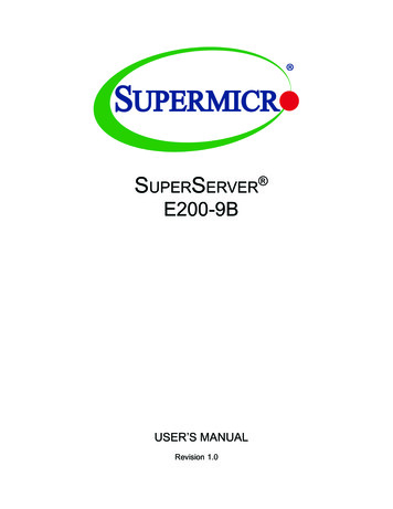
Chapter 1: Introduction1.3 Chassis FeaturesThe SCE300 is a compact embedded 1U chassis for Mini-ITX and a Flex-ATX motherboards.Front FeaturesThe front of the chassis includes the control panel.3456271Figure 1-1. Chassis Front and Control PanelControl Panel FeaturesItemFeaturesDescription1Power buttonThe main power switch applies or removes primary power from the power supplyto the server but maintains standby power. To perform most maintenance tasks,unplug the system to remove all power.2Reset buttonResets the system3Information LED Alerts operator to several states, as noted in the table below4 and 5NIC LEDIndicates network activity on the LAN when flashing.6HDD LEDIndicates hard disk drive activity when flashing.7Power LEDIndicates power is being supplied to the system power supply units. This LED isilluminated when the system is operating normally.9
SuperServer E300-9A-4C/E300-9A-8C User's ManualInformation LEDStatusDescriptionContinuously on andredAn overheat condition has occurred.(This may be caused by cable congestion.)Blinking red (1Hz)Fan failure, check for an inoperative fan.Blinking red (0.25Hz)Power failure, check for a non-operational powersupply.Solid blueUID has been activated locally to locate theserver in a rack environment.Blinking blueUID has been activated using IPMI to locate theserver in a rack environment.Rear FeaturesThe chassis rear holds input/output ports, described in chapter 3.2C1Figure 1-2. Rear Chassis ViewRear Chassis FeaturesItemFeaturesDescription1I/O PortsIPMI LAN, USB, LAN, VGA (further described in Chapter 3)2AOM WindowReserved for RJ45 console redirection cable3PCI BayBay for low-profile PCI-E add-on card103
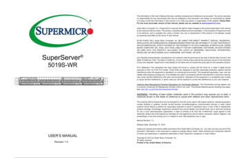
Chapter 1: Introduction1.4 Motherboard LayoutBelow is a layout of the A2SDi-4C-HLN4F/A2SDi-8C-HLN4F with jumper, connector andLED locations shown. See the table on the following page for descriptions. For detaileddescriptions, pin-out information and jumper settings, refer to Chapter 3.LEDM1UIDLAN2LAN4VGALAN1LAN3USB0/1IPMI LANJWD1UIDLED1JWD1COM1JPL1JGP1DESIGNED IN USAJPME2SRW1USB2/3JBT1JL1: :1-2:ENABLE2-3:DISABLEPRESS FITJD1:1-4:SPEAKERFANASATA DOM POWERSUPERDOMPRESS TA2JPV1JF1 PWR RST X OH/FF NIC NIC HDD PWRON21 LED L1BT1JSAS2I-SATA8-11JBT1BT1JMD1M.2:PCI-E 3.0 X2 / 1JSMB1JPH1USB2/3FANA1JSMB1JPI2C1CPU SLOT7 PCI-E 3.0 X4JI2C2BIOS BR1JBR1USB0/1IPMI LANALWAYS POPULATE DIMMA1 FIRSTLEDM1ADIMMB1DIMMB2DIMMA1DIMMA2BAR E MANUFACTURING MODEJWD1:WATCH BR1 2-3:BIOS RECOVERYJB3UIDLED1VGAJPG1JPG1JUIDBFAN2 FAN1Figure 1-3. Motherboard LayoutNotes: " " indicates the location of pin 1. Jumpers/LED indicators not indicated are used for testing only. The JSAS1 connector (I-SATA4-7) is not included on the A2SDi-8C-HLN4F.11JPV1
SuperServer E300-9A-4C/E300-9A-8C User's ManualQuick Reference TableJumperDescriptionDefault SettingJBR1BIOS RecoveryPins 1-2 (Normal)JBT1CMOS ClearOpen (Normal)JI2C1/JI2C2SMB to PCI-E Slots Enable/DisablePins 2-3 (Disable)JPG1VGA Enable/DisablePins 1-2 (Enabled)JPL1LAN Enable/DisablePins 1-2 (Enabled)JPME2ME Manufacturing ModePins 1-2 (Normal)JWD1Watch DogPins 1-2 (Reset)LEDDescriptionStatusLED1Onboard Power LEDSolid Green: Power OnLEDM1BMC Heartbeat LEDBlinking Green: BMC NormalUIDLED1UID LEDSolid Blue: Unit IdentifiedConnectorDescriptionBT1Onboard BatteryCOM1COM HeaderFAN1 - FAN3, FANASystem/CPU Fan Headers (FAN1: CPU Fan)IPMI LANDedicated IPMI LAN PortI-SATA0 - I-SATA3Intel SATA 3.0 Ports (I-SATA0 supports SuperDOM)JD1Speaker HeaderJF1Front Control Panel HeaderJGP1General Purpose I/O HeaderJL1Chassis Intrusion HeaderJMD1M.2 PCI-E 3.0 x2 / I-SATA SlotJPH14-pin Power Connector for HDD use (To provide power from the motherboard to onboard HDDdevices)JPI2C1Power Supply SMBbus I2C HeaderJPV14-pin DC Power Connector (To provide alternative power for special enclosure when the 24-pinATX power is not in use.)JPW124-pin ATX Power ConnectorJRT3Thermal Diode 1 HeaderJRT4Thermal Diode 2 HeaderJSAS1I-SATA Ports 4-7JSAS2I-SATA Ports 8-11 (Not available on A2SDi-4C-HLN4F)JSD1SATA DOM Power ConnectorJSMB1SMBus HeaderJTGLED1LAN3/LAN4 Front Activity LEDJTPM1Trusted Platform Module/Port 80 ConnectorLAN1 - LAN4Gigabit Ethernet (RJ45) Ports12
Chapter 1: IntroductionConnectorDescriptionSLOT7CPU PCI-E 3.0 x4 SlotSRW1, SRW2M.2 Holding ScrewsUIDUnit ID ButtonUSB0/1Back Panel Universal Serial Bus (USB) 2.0 PortsUSB2/3Front Accessible USB 2.0 HeaderUSB4Front Accessible USB 3.0 Type A PortVGAVGA Port13
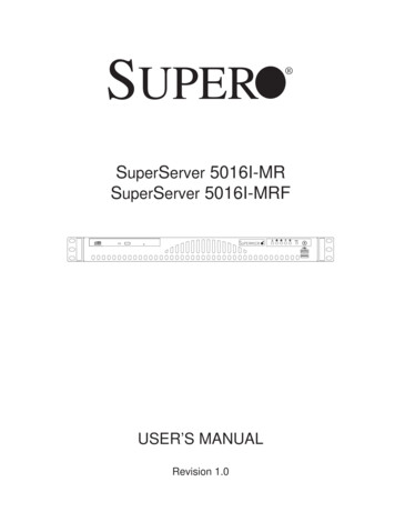
SuperServer E300-9A-4C/E300-9A-8C User's ManualChipset Block DiagramRGMII2GIGALANRTL8211FAST2400VGARJ45COM1 HEADERTPM1.2 HeaderPCIE SLOT X4PCIe 3.0 x48GT/sM.2 2280/2242SATA/PCIE SSDPCIe 3.0 x28GT/sSATA-III6Gb/s4 X SATA-III 2.0[0] LPC2400/2133/1866MHzDDR4 (CHB)IntelFCBGA13102400/2133/1866MHzLAN 0SGMIILAN 1mini-SAS CONNX28 X SATA-III1 X USB3.0 Type-A2 X USB2.0 RearSATA-III6Gb/sUSB3.05GbpsUSB2.0480Mbps2 X USB 2.0 1G-BaseTRJ45 X2RJ45 X2HSIO[11:4]SATA PORT11 4SGPIO[1:0]SGPIO[1:0]HSIO[19] USB2.0 [3]USB3.0USB2.0 [0/1]SMBUSUSB2.0480MbpsVR13DDR4 (CHA)CPLDLCMXO2GPIOExpanderUSB2.0 [2]Figure 1-4. Chipset Block DiagramNote: This is a general block diagram and may not exactly represent the features on yourmotherboard. See the System Specifications appendix for the actual specifications of yourmotherboard.14
Chapter 1: Introduction1-5 Server Installation and SetupThe server is shipped with the onboard processor and the motherboard pre-installed. Severalsteps are necessary to begin using your server. You must add memory, mount the hard diskdrive, and mount the system in place.Unpacking the SystemInspect the box in which the system was shipped and note if it was damaged. If the serveritself shows damage, file a damage claim with the carrier.Warnings and Precautions Use a regulating uninterruptible power supply (UPS) to protect the server from powersurges, voltage spikes and to keep your system operating in case of a power failure. Review the electrical and general safety precautions in Appendix B.Adding Components to your System Memory: If your system is not already fully integrated with system memory, refer to Chapter2 for details on compatible types of memory and the installation procedure. Drives and Storage: To add storage capabilities to your server, see Chapter 2.Input/Output: See Chapter 3 for I/O ports and connect them as needed.Software: See Chapter 4 for description and procedures for installing software, includingdrivers and monitoring programs.15
SuperServer E300-9A-4C/E300-9A-8C User's ManualInstalling Rack Mounting BracketsThe chassis can be mounted in a rack using two rack brackets and a two-part power adaptershelf bracket (optional, MCP-290-30002-0B).1. Attach the rack brackets using three screws through the holes in each bracket to securethe bracket to the chassis.2. Install the handles, using two screws through the bracket and into each handle.3. If you are using the optional power adapter bracket, install the power adapter on itsbracket. Place it as shown, then add the retention bracket using two screws.4. Mount the power adapter bracket assembly on the right side of the chassis using threescrews.Rack BracketRack BracketPower AdapterBracketFigure 1-5. Installing Rack Mounting Brackets16Power AdapterRetention Bracket
Chapter 2: Maintenance and Component InstallationChapter 2Maintenance and Component InstallationThis chapter provides instructions on installing and replacing main system components. Toprevent compatibility issues, only use components that match the specifications and/or partnumbers given.Installation or replacement of most components require that power first be removed from thesystem. Please follow the procedures given in each section.2.1 Removing PowerUse the following procedure to ensure that power has been removed from the system. Thisstep is necessary when removing or installing non hot-swap components or when replacinga non-redundant power supply.1. Use the operating system to power down the system.2. After the system has completely shut-down, disconnect the AC adapter power cord fromthe power source.3. Disconnect the power cord from the chassis.17
SuperServer E300-9A-4C/E300-9A-8C User's Manual2.2 Accessing the SystemThe SCE300 features a removable top cover to access to the inside of the chassis.23Figure 2-1. Removing the Chassis CoverRemoving the Top Cover1. Power down the system as described in section 2.1.2. Remove the two screws that hold the cover in place.3. Slide the cover sideways as illustrated above to release the front and rear cover hooksfrom the chassis.4. Lift the cover up and off the chassis.Caution: Except for short periods of time, do not operate the server without the cover inplace. The chassis cover must be in place to allow proper airflow and prevent overheating.18
Chapter 2: Maintenance and Component Installation2.3 Motherboard ComponentsInstalling MemoryMemory SupportThe A2SDi-4C-HLN4F/A2SDi-8C-HLN4F supports up to 128GB of ECC RDIMM or 64GBof ECC/non-ECC UDIMM DDR4 memory in four DIMM slots. Refer to the tables below foradditional memory information.Recommended Population tal System 2GB32GB128GB64GB128GBUnbuffered DDR4 ECC/Non-ECC DIMM MemoryDIMMs perchannelDIMMs perchannelDIMM TypePOR SpeedMT/sMemory PopulationSequence11UnbufferedDDR4 DIMM1866, 2133, 2400A1, A2 (2 DIMMs)22UnbufferedDDR4 DIMM1866, 2133, 2400A1, B1, A2, B2(4 DIMMs)19
SuperServer E300-9A-4C/E300-9A-8C User's ManualDIMM InstallationBegin by removing power from the system as described in Section 2.1 and removing thecover as described in Section 2.2.1. Insert DIMM modules in the following order: DIMMA1, DIMMB1, DIMMA2, DIMMB2. Forthe system to work properly, use memory modules of the same type and speed.2. Push the release tabs outwards on both ends of the DIMM slot to unlock it.3. Align the key of the DIMM module with the receptive point on the memory slot.4. Align the notches on both ends of the module against the receptive points on the slot.5. Seat the module firmly into the slot, pushing down with your thumbs evenly on bothsides of the module until it snaps into place.6. Press the release tabs to the lock positions to secure the DIMM module into the slot.DIMM RemovalReverse the steps above to remove the DIMM modules from the motherboard.Press both endsstraight downinto the memoryslot.NotchesRelease TabsFigure 2-2. Installing DIMMsNote: Visit the product page on the Supermicro website for possible updates to memorysupport (www.supermicro.com).20
Chapter 2: Maintenance and Component InstallationSolid State StorageThis motherboard supports two internally mounted solid state storage cards: One mini-PCI-E mSATA slot One M.2 slot supporting SATAFigure 2-2. Installing a Mini-PCI-E mSATA Card21
SuperServer E300-9A-4C/E300-9A-8C User's ManualMini-PCI-E mSATAThe A2SDi-4C-HLN4F/A2SDi-8C-HLN4F supports a PCI-E x4 slot for NVMe drives. ThemSATA is muxed with the I-SATA5.M.2M.2 is formerly known as Next Generation Form Factor (NGFF). TheA2SDi-4C-HLN4F/A2SDi-8C-HLN4F deploys an M key (2242/2280) dedicated for SSDdevices with the ultimate performance capability in a PCI Express 3.0 x4 interface for nativePCI-E SSD support. The M.2 is muxed with the I-SATA4 port for legacy SATA SSD devices.Installing the M.2 Card1. Access the motherboard and locate the M.2 connector (Figure 1.3, JMD1: M2)2. Gently insert the M.2 card into the connector.3. Use a screw to secure the M.2 card to the M2 SRW1 or M2 SRW2 standoff.22
Chapter 2: Maintenance and Component InstallationMotherboard BatteryThe motherboard uses non-volatile memory to retain system information when system poweris removed. This memory is powered by a lithium battery residing on the motherboard.Figure 2-3. Installing the Onboard BatteryReplacing the Battery1. Remove power from the system as described in section 2.1 and remove the chassiscover as described in section 2.2.2. Push aside the small clamp that covers the edge of the battery. When the battery isreleased, lift it out of the holder.3. To insert a new battery, slide one edge under the lip of the holder with the positive ( )side facing up. Then push the other side down until the clamp snaps over it.Note: Handle used batteries carefully. Do not damage the battery in any way; a damagedbattery may release hazardous materials into the environment. Do not discard a used batteryin the garbage or a public landfill. Please comply with the regulations of your local hazardouswaste management agency to dispose of your used battery properly.Warning: There is a danger of explosion if the onboard battery is installed upside down (whichreverses its polarities). This battery must be replaced only with the same or an equivalenttype recommended by the manufacturer (CR2032).23
SuperServer E300-9A-4C/E300-9A-8C User's Manual2.4 Chassis ComponentsInstalling the Storage DriveThe SCE300 can accommodate two fixed 2.5" drives, one with bracket, one on a base mount(only one fixed drive supported when the AOC area is occupied). Use enterprise quality drivesonly.Figure 2-4. Installing the Hard DriveInstalling the Hard DriveThe motherboard should be installed before installing the drive.1. Remove power from the system as described in section 2.1 and remove the chassiscover as described in section 2.2.2. Remove the screws securing the hard drive tray to the support bracket and set themaside for later use. Lift the tray out.3. Place the drive into the tray and secure it to the tray with the screws provided with drive.24
Chapter 2: Maintenance and Component Installation4. Return the drive tray assembly into the chassis, aligning the tabs of the tray with theslots in the chassis. Secure the tray to the chassis support bracket with the screwspreviously set aside.5. Attach the cable SATA connector and to the motherboard connector. This cable carriesboth the SATA signal and the SATA power.6. Reinstall the chassis cover and power up the system.Installing the Riser CardThe system can support one PCI-E x8 expansion card by means of an optional riser card.The riser card is inserted in the expansion slot on the motherboard. Installation of the risercard and riser card bracket is pictured below.Riser Card BracketRiser CardFigure 2-5. Installing the Riser Card25
SuperServer E300-9A-4C/E300-9A-8C User's ManualSystem CoolingThe SCE300 includes two replaceable 4-cm fans. An optional third fan can be purchased.Replacing the System Fan1. Remove power from the system as described i
support@supermicro.com (Technical Support) Website: www.supermicro.com Europe Address: Super Micro Computer B.V. Het Sterrenbeeld 28, 5215 ML 's-Hertogenbosch, The Netherlands Tel: 31 (0) 73-6400390 Fax: 31 (0) 73-6416525 Email: sales@supermicro.nl (General Information) support@supermicro.nl (Technical Support) rma@supermicro.nl (Customer .