Transcription
CONSTRUCTION STANDARDSDIVISION 22 - PLUMBINGDIVISION 22 PLUMBINGSection 22 00 00 – Plumbing General System DesignsPART 1: GENERAL1.1Scope of Standards:A. Plumbing Code Compliance: Comply with 2015 Uniform Plumbing Code, toselection and installation of Plumbing materials and products. (SHALL EXCLUDEAPPENDIX L, ALL OF SECTION L 8.0 Circuit VentingThrough L8.5, OF UPC 2009 CODE.)B.1.2The design guidelines contained herein include the requirements for systems,materials, fittings, and valves utilized for plumbing systems at Texas StateUniversity. It is the intention of this document to provide a standard for pipingsystems at Texas State University in order to provide the highest level of qualityand standardization possible; it is not intended to be a guide specification.Design GuidelinesA.General1.Building Drainage, Waste and Vent System, use Cast Iron Pipe with noHub Couplings, Basis of Design shall be Hi-Torq 125 Couplings.2.All indirect drains shall be piped to a floor drain or floor sink. (A/C, ReliefValves, Pan Drains, etc.)3.Building Drainage Systems – all venting to be properly sized and airadmittance valves are strictly prohibited.4.Building Drainage System – Horizontal Double Combination (any size) isstrictly prohibited.5.Seal all openings around piping.6.Provide metal sleeves for piping passing through walls to provide fireprotection equivalent to initial requirements.7.In lavatories separately valve each riser pipe.8.Always provide siphon breakers in pipe lines to hose bib-type faucets.9.Use plugged tees rather than elbows to provide clean out points inplumbing piping.Revised March 2021Plumbing General System Design-22 00 00-1
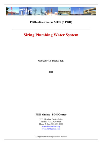
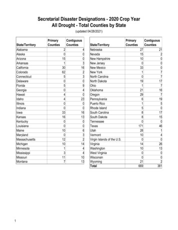
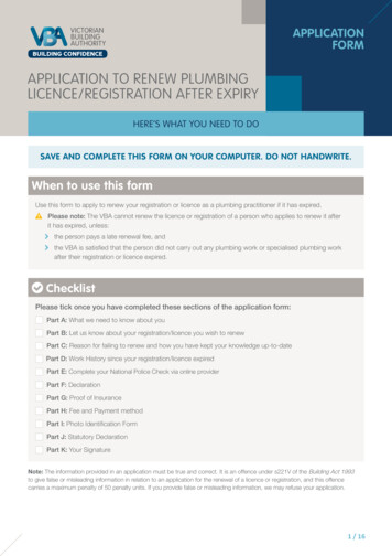
CONSTRUCTION STANDARDSDIVISION 22 - PLUMBING10.Provide all take-offs from main water supply lines with cutoff valves andprovide sufficient clearance for access to valves.11.Provide enough valving so that plumbing systems can be closed down insections.12.Provide permanent “as-constructed” drawings which show locations of allpiping systems, including those underground.13.Use an identification system and a color-coding system for plumbing andpiping systems as described in mechanical section of these standards.14.Provide keyed hose bibs within 20’ of main entrance and rear exit nomore than 100’ apart around outside perimeter of a new building.Outdoor hose bib shall be non-freeze proof type.15.All valves concealed within enclosing construction shall be madeaccessible via appropriate metal access doors. Their location and sizeshall be provided to the architect/engineer with a record document to besigned off on.16.When using PVC (in lieu of Cast Iron for building drainage systems)under slab on grade foundations, do not use test tees (see attachedPhoto).Revised March 2021Plumbing General System Design-22 00 00-2
CONSTRUCTION STANDARDS17.B.C.DIVISION 22 - PLUMBINGMixing cast iron pipe and PVC pipe, under slab, is strictly prohibited onbuilding drainage (sanitary) system. See attached photoPlumbing Fixture Standardization: (only floor mount, floor outlet water closets)1.Standardize plumbing fixtures for Texas State University as much aspossible.2.With each new construction project verify plumbing fixture selectionswith Project Manager prior to finalizing the specification of plumbingfixtures.3.Specify plumbing fixtures which have been establish as Texas StateUniversity standards.4.Refer to plumbing section for standard plumbing products.5.For energy conservation, where water saving devices have beendeveloped and proven such as reduced flow shower heads they will beused.Floor Drains1.Provide floor drains, minimum 3”, in all restrooms and custodial closets.a.Do not provide drains in elevator pits, (only).2.For drains in Restroom/Bathroom for Public use, provide minimum 3”pipe size. Large restrooms may require 2 or more floor drains.3.Slope floor to drains, slope floor just around floor drain is not allowed.Revised March 2021Plumbing General System Design-22 00 00-3
CONSTRUCTION STANDARDSD.4.Floor Drain Traps installed in inaccessible areas shall be brought to theattention of Texas State University for consideration of priming at thattime. No drain seal use trap; primers on floor drains.5.All pressure relief type trap primary devices shall be connected to a directdrop that supplies a single fixture.6.All traps that are remote from a commonly used fixture shall have anelectro mechanical trap primer for single or multiple primary connectionsand must be readily accessible.Floor Sinks1.Provide 16’ X 16” floor sinks in Mechanical Rooms.a.E.Alternate: Trench DrainsPipe Chases1.Size pipe chases to be large enough to accommodate the piping to behoused in chases and to be accessible. Locate piping in chases to avoidthe obstruction of entrances or openings to pipe chases.a.F.DIVISION 22 - PLUMBINGMinimum pipe chase width is 42”.Access to Plumbing1.Provide minimum of 3’6” crawl space beneath new buildings. Provideeasy access to crawl space.2.Provide lights in crawl space which switch at access.3.Equip access doors with locks keyed to campus master and grand masterkey.4.Grade crawl space toward gravel-filled trenches provided with perforateddrainage pipe.5.Provide all spaces below grade with perimeter drain system.6.Plan for clean outs at each corner and at high points of subsurfacedrainage system.7.Provide adequate space for working on plumbing and piping. See Specsection Campus Standard 08-31-00 1.02 C 1 thru 4 – no exceptions.8.Afford easy access to all working parts of all plumbing devices.Revised March 2021Plumbing General System Design-22 00 00-4
CONSTRUCTION STANDARDSDIVISION 22 - PLUMBING9.Do not permanently seal in masonry wall those items of plumbingrequiring periodic maintenance or repair.10.Pipes should not be run above electric panels, transformers, etc.11.Provide adequate crawlspace ventilation.12.Use forced air ventilation of crawlspace if crawlspace is below grade.13.Design for crawlspace air charge as determined by soil test results.Water MetersG.1.Include a water meter in each new building and remodel of old buildings ifneeded.a.Provide a Backflow Preventer at Meter1. Use Watts 909, 919 or 957 (depending on size of line)2. Watts 009 is strictly prohibitedb.H.I.1.Refer to Section 25 51 00 2.7I Field Devices - Integrated AutomationFacility Controls for acceptable domestic water meter.2.Locate the meter inside a machine room, install meter horizontally nohigher than 5” high and no lower than 12” AFF.Pressure Gauge1.Include a 1-200 psi pressure gauge, 4-inch or larger, on the domesticwater header.2.Also include an electronic pressure sensor on the header, suitable forconnection to Owner’s FCMS system.Pipe Size1.J.K.All Bypass systems shall have a Backflow PreventerAvoid 2-1/2, 3-1/2 and 5-inch pipe.Solder1.Must comply to Uniform Plumbing Code 316.1.32.Pro Press systems are acceptable.Floor SinksRevised March 2021Plumbing General System Design-22 00 00-5
CONSTRUCTION STANDARDS1.L.There shall be one 16” X 16” floor sink with 4” outlet pipe size per airhandler for fin water (condensate from cooling coils), and one 12”x12”floor sink per pump battery to facilitate multiple condensate lines, and toeliminate trip hazard of condensate lines routed over floors.Fin Water1.M.DIVISION 22 - PLUMBINGFin water may be recovered in some buildings.Water Softening1.Provide water piping by pass on softener. Bypass will need to beprotected by a backflow device.2.Domestic water feed to heating hot water shall be softened using salt-ionexchange.a.Also provide Backflow Preventer on Softener.1. Use Watts 957 for 2-1/2” and larger2. Use Watts 919 for 2” and smaller3. Watts 009 is strictly prohibited3.Water shall be tested for hardness and softening system shall be selectedto reduce hardness to acceptable level and sized for building demand.Install test ports (hose bib) for each unit for testing of hardness.4.Brine storage tank shall be sized for no less than monthly service.5.System shall consist of two ion exchange tanks each sized for seven (7)days of service.a.6.N.O.No rain bird products.All air admittance valves (auto vents) are prohibited.Vaults1.Must meet manufacturer’s clearances for backflow preventer.2.Access door/hatch opening shall be 36” to 42” or larger.Water Mains and Distribution Water Lines1.Revised March 2021Water mains 4” and larger use Ductile Iron Pipe/fittings. 3” and Smallershall be copper, type K with a 6 mil poly sleeve.Plumbing General System Design-22 00 00-6
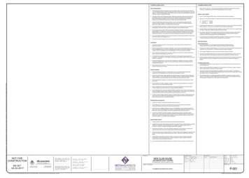
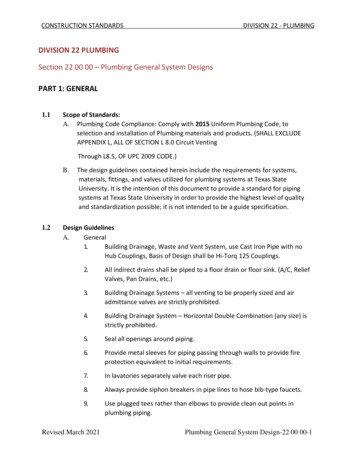
CONSTRUCTION STANDARDS2.DIVISION 22 - PLUMBINGAWWA C-900, DR 14 water pipe is acceptable where there are no SteamLines in the area.a.C-900 or Ductile Iron, Pipe to Pipe joints shall have joint restraints andall Ductile Iron fittings shall be mechanical joints with joint restraints (noexceptions)3.All underground PVC (C-900) water distribution pipe must have 12-gaugeTracer Wire.4.A) Refer to AWWA C605-5 for underground installation of PVC PressurePipe and fittings for water.b) Refer to AWWA C600-5 Installation of Ductile Iron water mains5.Use Resilient Wedge Gate Valves on water distribution mains and providea 4”x16”x4” concrete pad for proper support of the valve.6.Use only stainless steel tapping sleeve. Basis of Design, Smith Blair#665-142512Smith-Blair Tapping SleevesTapping Sleeve w/MJ Outlet Option Available on all SB Carbon Steel andStainless, Steel Tapping Sleeves Use 665-142512MJ-2007.Fittings:a.Use EBAA iron pipe joint restraint (mega lugs) on all mechanicaljoints.b.Use mega lugs restraint harness for push-on pipe (pipe to pipe)c.Use polyethylene sleeve wrap on Ductile Iron Pipe and mechanicaljoint fittings.d.90, 45, ells, tees, 22 ½, or turn of direction shall have a thrustblock.P.Domestic Utility Water Lines shall have a 4”x16” concrete pad under valves forproper support.Q.Sewer MainsRevised March 2021Plumbing General System Design-22 00 00-7
CONSTRUCTION STANDARDS1.O.Sewer mains shall be a minimum of SDR 26, Heavy Wall, gasket sewerfittings, with 12-gauge tracer wire. Bell Ends must be installed upstreamof flowStorm Drains1.P.DIVISION 22 - PLUMBINGStorm lines shall be a minimum of SDR 26 Heavy wall, gasket sewer fittingwith 12-gauge tracing wire.Roof Drains1.Drain inlets and outlets are to be 6” in diameter, minimum.2.Downspouts are to be 5” square, minimum, in Copper.PART 2: PRODUCT (NOT USED)PART 3: EXECUTION (NOT USED)END OF SECTION 22 00 00Revised March 2021Plumbing General System Design-22 00 00-8
DIVISION 22 PLUMBING Section 22 00 00 - Plumbing General System Designs PART 1: GENERAL 1.1 Scope of Standards: A. Plumbing Code Compliance: Comply with 2015 Uniform Plumbing Code, to selection and installation of Plumbing materials and products. (SHALL EXCLUDE APPENDIX L, ALL OF SECTION L 8.0 Circuit Venting Through L8.5, OF UPC 2009 CODE.) B.