Transcription
14 20 00/OTIBuyLine TION PROCESSHYDRAULIC ELEVATORSGEN2 MACHINE– ROOMLESS ELEVATORESCALATORSFINISHES AND FIXTURES
Otis.the global leader in elevator and escalator systemsPlanning and design programsto meet every needBefore You Begin:Otis Elevator Company, the world’s leadingmanufacturer of elevator and escalator systems,meets the most rigid demands of planning, buildingand design professionals. We offer you two easy-touse planning and selection guides: Architect’s Assistant—Available on Otis.com.Thissimple, online plug-and-play program will generatecustomized CSI specifications and CAD drawings.It will help you design and build an elevatorthat meets building specification and coderequirementsStep 2: Elevator Quantity and Size These are determined by floor population, buildinguse or building type and national and local codes Our E-Z Elevator Selection Process 3,500-lb capacity with center-opening door isThese two distinct planning and selection tools aredesigned to help you meet the most demandingproject requirements quickly and cost-effectively.common for mid- to high-rise buildingsRefer to Architect’s Assistant at Otis.com for additional help in selecting propersize and number of elevators.Step 3: Hoistway RequirementsOtis E-Z Elevator Selection ProcessStep 1: Travel Height Selecting the optimal elevator type for yourproject depends upon the elevator travel distance The chart below identifies Otis elevators mostcommonly selected for specific travel heights(see product pages in this guide for other criteria):Elevator Selection ChartUse this chart to determine which elevators are applicable forspecific travel heights. Colors indicate recommended range ofminimum and maximum travel height.ElevonicHigh-RiseGearless400 and aboveGen2MachineRoomless300 Assess specific requirements by reviewing individual product pagesin this guide.Step 4: Machine/Control Room RequirementsHydraulic Systems Separate machine room required at bottom landing Machine room can be located remotely or adjacentto hoistway at bottom landingGen2 Machine-Roomless System Requires separate control space/room Flexible control space/room placement—up to 150feet away from top of hoistway (depending onwiring configuration within the building)Step 5: Car Design and Finishes100 60 TelescopicHolelessRopedHolelessHoled30 Travel heightseismic zones 2 or greater, additional hoistwayspace is requiredRequired dimensions will be found on specific product pages in this guide.Consult your Otis representative for specific requirements.200 20 To accommodate heavier reinforcements to rails in Otis offers flexibility in designing and selecting carwalls, ceilings, lighting, handrails, bumper rails andfixturesSee page 7 for additional information.Holeless0 Otis Hydraulic Elevators Otis Traction ElevatorsVisit www.otis.com for the latest information2
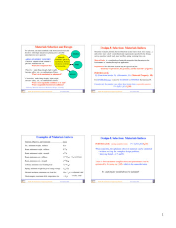
Holeless HydraulicTravel Height– MaximumMaximum stopsSpeed (ft/min)14 20 00/OTIBuyLine 1035E20 ft3100, 125ABFIHPLANDGHoisting Beam(Not by ger elevatorsRated lbs.Passenger Capacity 1Car 2A Interior widthB Interior depthC Interior heightD Car door widthHoistwayE WidthWidth in seismic zones 3F Depth 4G Rough opening widthH Rough opening heightI Clear opening heightJ Clear overhead to hoist beam@ 100ft./min.@ 125ft./min.K Minimum pit depth 5Machine RoomL Number of elevators in groupWidth x 450030/28500033/315000 AIA33/315 -8 4 -3 5 -8 4 -3 6 -8 4 -3 5 -8 7 -11 5 -11 8 -6 5 -8 9 -0 3 -0 3 -0 3 -6 6 -8 6 -8 4 -9 5 -5 8 -0 (Optional 9 -7 )3 -6 3 -6 4 -0 4 -6 4 -0 7 -4 7 -6 5 -9 4 -8 7 -4 7 -6 5 -9 4 -8 8 -4 8 -6 5 -9 5 -2 8 -4 8 -6 6 -3 5 -2 7 -7 7 -7 9 -8 5 -8 8 -4 8 -4 10 -3 6 -2 7 -7 7 -7 10 -9 5 -8 12 -4 12 -4 12 -5 12 -8 4 -0 (5 -0 for Canadian Province of Ontario) to 7 -6 depending on rise12 -4 1 Capacity2 Interior3 InService elevators8 -4 8 -6 6 -11 5 -2 Hydraulic ElevatorsKey Attributes No need for well hole drilling and itsassociated costs Above-ground solution substantially reducesrisk of soil and ground water contamination Applicable for:– Hazard-sensitive sites– Waterfront sites– Existing buildings Available in both passenger and serviceelevator configurations and capacities Solid-state starter improves performancethrough precise control of electric current Optional:– Front and rear entrances– Ceiling height of 9 -7 – 8 -0 clear opening– Glassback– REM remote elevator monitoring7 -10 7 -0 (Optional 8 -0 )12 -4 12 -4 12 -4 15 -9 x 7 -4 code requirements: US/Canada.dimensions may vary depending on interior finishes.seismic zones 2 or greater.4 Forcars with front and rear doors, add 9 1 4 to depth for 2000 to 3500 lb.capacities; add 12 1 4 for 4500 and 5000 lb. capacities.12 -4 211 -6 x 8 -6 317 -0 x 8 -6 422 -0 x 8 -6 5 Pitdepth changes based on speed: For 100 fpm, pit depth increases1 in depth for each 1 increase in rise over 13 -7 up to 20 -0 .For 125 fpm, pit depth increases 1 in depth for each 1 increase in rise over12 -8 up to 20 -0 .Visit www.otis.com for the latest information3
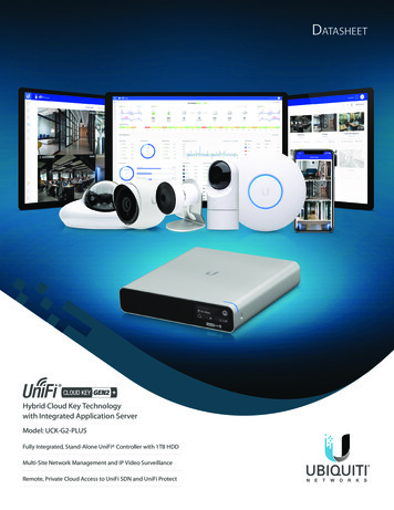
Telescopic Holeless HydraulicTravel Height– MaximumMaximum stopsSpeed (ft/min)E44 ft 1 in5100, 125ABFIHPLANKey Attributes No need for well hole drilling and itsassociated costs Above-ground solution substantially reducesrisk of soil and ground water contamination Applicable for:– Hazard-sensitive sites– Waterfront sites– Existing buildings Available in passenger elevator configurationsand capacities only Solid-state starter improves performancethrough precise control of electric current Optional:– Front and rear entrances– Ceiling height of 9 -7 – 8 -0 clear opening– Glassback– REM remote elevator monitoringHydraulic ElevatorsDimensionsDGHoisting Beam(Not by Otis)CJPlungerMachineRoomLKSECTIONPassenger elevatorsRated lbs.20002100250030003500Passenger Capacity113/1213/1216/1520/1823/21Car 2A Interior width5 -8 5 -8 6 -8 6 -8 6 -8 B Interior depth4 -3 4 -3 4 -3 4 -9 5 -5 C Interior height8 -0 (Optional 9 -7 )D Car door width3 -0 3 -0 3 -6 3 -6 3 -6 HoistwayE Width (rise up to 30 ft 1 in)7 -4 7 -4 8 -4 8 -4 8 -4 Width (rise up to 30 ft 1 in) in seismic zones 37 -6 7 -6 8 -6 8 -6 8 -6 Width (rise over 30 ft 1 in)7 -10 7 -10 8 -10 8 -10 8 -10 5 -9 5 -9 5 -9 6 -3 6 -11 F Depth 44 -8 4 -8 5 -2 5 -2 5 -2 G Rough opening width7 -10 H Rough opening height7 -0 (Optional 8 -0 )I Clear opening heightJ Clear overhead to hoist beam(rise up to 30 ft 1 in)@ 100ft./min.12 -8 @ 125ft./min.12 -11 Clear overhead to hoist beam (rise over 30 ft 1 in)@ 100ft./min.13 -0 @ 125ft./min.13 -2 4 -0 (5 -0 for Canadian Province of Ontario) to 7 -6 depending on riseK Minimum pit depth5Machine RoomL Number of elevators in group1234Width x depth5 -9 x 7 -4 11 -6 x 8 -6 17 -0 x 8 -6 22 -0 x 8 -6 1 Capacity4 For2 Interior5 Maximumcode requirements: US/Canada.dimensions may vary depending on interior finishes.3 In seismic zones 2 or greater. A 3-stage plunger mayrequire extra hoistway width. Please consult your localOtis representative.4cars with front and rear doors add 9 1 4 to depth.rise with 4 -0 pit depth is 34 -4 . Consult Otis.com oryour local Otis representative.Visit www.otis.com for the latest information
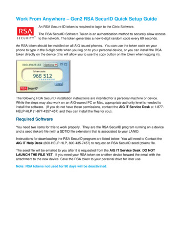
Holed HydraulicTravel Height– MaximumMaximum stopsSpeed (ft/min)14 20 00/OTIBuyLine 1035E60 ft7100, 125, 150ABFIHPLANKey Attributes Well hole drilling required PVC protection surrounds wall and bottomof in-ground cylinder to prevent contact withunderground contaminants Solid-state starter improves performancethrough precise control of electric current Available in both passenger and serviceelevator configurations and capacities Optional:– Front and rear entrances– Ceiling height of 9 -7 – 8 -0 clear opening– Glassback– REM remote elevator monitoringDGHoisting Beam(Not by Otis)CJPlungerMachineRoomLKWell Hole(Required)Cylinder withPVC ProtectionSECTIONDimensionsPassenger elevatorsRated lbs.Passenger Capacity1Car 2A Interior widthB Interior depthC Interior heightD Car door widthHoistwayE WidthWidth in seismic zones3F Depth 4G Rough opening widthH Rough opening heightI Clear opening heightJ Clear overhead to hoist beam@ 100 ft./min.@ 125 ft./min.@ 150 ft./min.K Minimum pit depthMachine RoomL Number of elevators in groupWidth x 500033/315000 AIA33/315 -8 4 -3 5 -8 4 -3 6 -8 4 -3 5 -11 8 -6 5 -8 9 -0 3 -0 3 -0 3 -6 6 -8 6 -8 5 -8 4 -9 5 -5 7 -11 8 -0 (Optional 9 -7 )3 -6 3 -6 4 -0 4 -6 4 -0 7 -4 7 -6 5 -9 4 -8 7 -4 7 -6 5 -9 4 -8 8 -4 8 -6 5 -9 5 -2 8 -4 8 -6 6 -3 5 -2 7 -5 7 -7 9 -8 5 -8 8 -2 8 -4 10 -3 6 -2 7 -5 7 -7 10 -9 5 -8 12 -0 12 -0 12 -0 12 -0 12 -3 12 -3 12 -3 12 -3 12 -3 12 -3 12 -3 12 -3 4 -0 (5 -0 for Canadian Province of Ontario)12 -5 12 -8 12 -8 12 -0 12 -3 12 -3 1 Capacity2 Interior8 -4 8 -6 6 -11 5 -2 Hydraulic ElevatorsService elevators350023/217 -10 7 -0 (Optional 8 -0 )12 -0 12 -3 12 -3 12 -0 12 -3 12 -3 15 -9 x 7 -4 code requirements: US/Canada.dimensions may vary depending on interior finishes.211 -6 x 8 -6 3317 -0 x 8 -6 422 -0 x 8 -6 In seismic zones 2 or greater.cars with front and rear doors, add 9 1 4 to depth for 2000 to 3500 lb.capacities; add 12 1 4 for 4500 and 5000 lb. capacities.4 ForVisit www.otis.com for the latest information5
Machine-Roomless ElevatorTravel Height– MaximumMaximum stopsSpeed (ft/min)GF196 ft @ 200 (ft/min)300 ft @ 350 (ft/min)300 ft @ 400 (ft/min)30200, 350, 400ECBLPLANDIMPORTANT:To assist in your planning, we recommend that you callyour Otis representative at the beginning of the project.IAKey Attributes Space-saving configuration eliminates the need for a machine room Flexible control space/room placement up to 150 feet away from JKHtop of hoistway (depending on wiring configuration within the buildingMachine room version of Gen2 available at speeds up to 500 ft/min.Available with CompassTM Destination Entry SystemNHBufferMSECTIONDimensions1Gen2 Machine-Roomless ElevatorFront0HAIA OpeningRated lbs.Passenger elevators21002Passenger Capacity 313/12Car 4A Interior width5 -8 B Interior depth4 -3 C Interior height 5D Car door width3 -0 HoistwayWidth7 -4 E Single hoistway 6In seismic zones 67 -4 F Double hoistway 615 -0 In seismic zones 615 -0 22 -8 G Triple hoistway 6In seismic zones 622 -8 6 -71 2 H DepthIn seismic zones6 -71 2 4 -8 I Rough opening widthJ Rough opening heightK Clear opening height7L Total overhead for 8 -0 car@ 200 ft/min14 -7 @ 350 ft/min15 -31 2 @ 400 ft/min–Total overhead for 9 -7 car@ 200 ft/min–@ 350 ft/min–@ 400 ft/min–M Minimum pit depth@ 200 ft/min@ 350 ft/min@ 400 ft/min–Control Space/RoomN Control space–simplexControl room–simplexControl room–duplexService elevators25003000350040004000H4500H5000H5000H AIA16/1520/1823/2127/2527/2530/2833/3133/316 -85 16 4 -31 8 6 -85 16 4 -9 5 -85 16 7 -5 5 -85 16 7 -11 5 -115 16 8 -6 5 -85 16 9 -0 3 -6 3 -6 4 -0 4 -0 4 -6 4 -0 8 -4 8 -6 17 -0 17 -4 25 -8 26 -2 6 -71 2 6 -71 2 5 -2 8 -4 8 -6 17 -0 17 -4 25 -8 26 -2 7 -11 2 7 -11 2 5 -2 8 -2 8 -4 16 -8 17 -0 25 -2 25 -8 9 -2 9 -2 5 -8 8 -2 8 -4 16 -8 17 -0 25 -2 25 -8 9 -8 9 -8 5 -8 8 -5 8 -7 17 -2 17 -6 25 -11 26 -5 10 -3 10 -3 6 -2 8 -2 8 -4 16 -8 17 -0 25 -2 25 -8 10 -9 10 -9 5 -8 6 -85 16 7 -85 16 5 -5 5 -5 8 -0 (Optional 9 -7 )3 -6 4 -0 8 -4 8 -6 17 -0 17 -4 25 -8 26 -2 7 -10 7 -10 5 -2 9 -4 9 -6 19 -0 19 -4 28 -8 29 -2 7 -10 7 -10 5 -8 7 -10 7 -0 (Optional 8 -0 )14 -93 16 15 -59 16 16 -0 14 -93 16 15 -59 16 16 -0 14 -93 16 15 -59 16 16 -0 14 -93 16 15 -59 16 16 -0 14 -93 16 15 -59 16 –14 -93 16 15 -59 16 –14 -93 16 15 -59 16 –14 -93 16 15 -59 16 –16 -43 16 17 -09 16 17 -7 16 -43 16 17 -09 16 17 -7 16 -43 16 17 -09 16 17 -7 16 -43 16 17 -09 16 17 -7 16 -43 16 17 -09 16 –16 -43 16 17 -09 16 –16 -43 16 17 -09 16 –16 -43 16 17 -09 16 –––––4 -111 4 5 -51 4 5 -8 5 -8 5 -8 5 -8 H x 2 -10 widthH x 5 -0 widthH x 7 -0 widthThe 9 -7 car interior height does not apply to the 2100 lb. duty.1 For52 Maximum6 Forglassback dimensions visit Otis.com or contact your Otis representative.travel for 2100 lb. car is 196 ft. @ 200 fpm and 164 ft. @ 350 fpm.3 Capacity code requirements: US/Canada.4 Interior dimensions may vary depending on interior finishes.elevators with occupied space below, this dimension may change.Consult your Otis representative for dimensions.7 The 8 -0 height does not apply to the 2100 lb. duty.Visit www.otis.com for the latest information6
EscalatorsMaximum rise14 20 00/OTIBuyLine 103521 ft 4 in (NCE model)LOWER LANDINGKey Attributes Quiet and smooth operation ensured byhypoid helical gear drive, which produceslower noise levels [maximum 55 dB(A)] anduses less energy than conventional wormgear machines Guardian skirt panels with extremely lowcoefficient of friction to reduce risk of objectsbecoming entrapped Rigid impact-resistant stainless steel profileUPPER LANDINGABDEdge ofuppersupportWorkpointEdge oflowersupportEFinishedFloorFWorkpointCGNCE ModelA Step widthB Finish widthC Minimum pit openingD Minimum rough openingE Maximum riseMinimum riseF Minimum pit depthG Beam-to-beam calculation15063224 3 -9 14 -7 3 16 4 -0 1 8 5064032 4 -5 14 -7 3 16 4 -8 1 8 5064840 5 -1 14 -7 3 16 5 -41 8 21 -4 4 -111 16 3 -55 8 1.732 x E 17 -103 8 21 -4 4 -111 16 3 -5 5 8 1.732 x E 17 -103 8 21 -4 4 -111 16 3 -5 5 8 1.732x E 16 -211 16 Escalators/Finishes and FixturesELEVATIONDimensions1Dimensions listed assume 2 flat steps and escalatoris installed under non-seismic conditions.Finishes and FixturesNo matter what your most critical designcriteria—aesthetic, budgetary, maximumdurability—Otis offers an exceptional degreeof flexibility in the selection of: Entrance frames and doors Car interior surfaces Car ceilings and lighting solutions Handrails and bumper rails Car and hall fixtures, including operatingpanels, hall lanterns and position indicatorsIn addition to a broad palette of standardinterior finishes,
GEN2 MACHINE–ROOMLESS . customized CSI specifications and CAD drawings. It will help you design and build an elevator that meets building specification and code requirements Our E-Z Elevator Selection Process These two distinct planning and selection tools are designed to help you meet the most demanding project requirements quickly and cost-effectively. Visit www.otis.com for the .