Transcription
AC 2010-926: SELECTION OF MATERIAL, SHAPE, AND MANUFACTURINGPROCESS FOR A CONNECTING RODSomnath Chattopadhyay, Pennsylvania State UniversityPage 15.1057.1 American Society for Engineering Education, 2010
Selection of Material, Shape and Manufacturing ProcessFor a Connecting RodABSTRACTThis activity centers on the courses of strength of materials and production design offered at asophomore level Mechanical Engineering curriculum. A connecting rod is one of the mostmechanically stressed components in internal combustion engines. The objective of the activityis to select the appropriate material for a connecting rod where the constraints are to make theproduct as light and cheap as possible and yet strong enough to carry the peak load withoutfailure in high cycle fatigue. The fracture toughness also needs to be above a certain minimumvalue. A further requirement is that the connecting rod should not buckle during operation.These constraints are used to select an appropriate cross section and material for construction.The next phase involves the selection of manufacturing process for which the constraints areshape, mass, quality and economics. The selections of the material, the cross-sectional shape andthe manufacturing processes involve the use of CES EduPack, which yields materials that meetthe constraints. The current manufacturing processes for connecting rods by fracture split dropforging and fracture split powder forging are highlighted and compared based on currentinformation.INTRODUCTIONA connecting rod in a high performance engine is subjected to inertial forces and bearing loads.It should be able to withstand these forces for a large number of cycles. In order to reduce theforces exerted during operation, the connecting rod should weigh as little as possible and shouldhave very high fatigue strength. The connecting rod undergoes cyclic tension, compression aswell as bending. The connecting rod is subjected to a combination of axial and bending stresses.Furthermore the connecting rod is subjected to a large compressive load so that it is imperativethat buckling does not occur. To mitigate this problem, „I‟- section is commonly used. A furtherconsideration involves the shape of the cross-section. When a structural member is subjected toan axial tension the area of the cross-section is important but the shape is not. All sections withthe same area will carry the same load. For bending, an „I‟-section is better than a solid sectionof the same cross-sectional area. To characterize this, we need a metric – a way of measuring thestructural efficiency of a section shape, independent of the material which the connecting rod ismade of. We define the shape factor of a section as the ratio of stiffness or strength of theshaped section to that of a „neutral‟ reference shape typically a solid square cross-section withthe same cross-sectional area. The material selection as influenced by the shape is outlined inthis work. The selection is also based on the application of an additional standard constraint thatthe fracture toughness should exceed 15 MPa m.Page 15.1057.2In order to select the proper manufacturing process, the economic, technical and qualityconstraints are employed. The economic constraints involve raw material cost and batch sizeused in production. The technical constraints consist of estimated connecting rod mass and aminimum section of the connecting rod. The quality constraints involve manufacturing tolerance
and surface roughness. The competitive processes of powder methods and forging are carefullyinvestigated tracking the latest developments in alloy development.Ashby (2005) has indicated a procedure for selection of material for a connecting rod based onthe constraints of high cycle fatigue and elastic buckling and has concluded the alloys ofmagnesium, titanium, beryllium and aluminum as potential choices for connecting rod materials.Ashby, Shercliff and Cebon (2008) have identified high strength magnesium, aluminum and ultrahigh strength steels as attractive candidates for connecting rod materials based on the constraintsof high cycle fatigue and fracture toughness. They have also refined the search on connectingrod materials and identified aluminum reinforced with silicon carbide, boron or alumina fibers,beryllium alloys and a number of high performance carbon reinforced composites. Farag (2002)has listed some of the general (not specific to connecting rod) material performance requirementsand has related possible modes of failure with the material properties. He states that thecatastrophic fracture due to impact loading is resisted by the high fracture toughness, which is arigid material requirement and should be used for initial screening of materials. He also statesthat the local and the global buckling are resisted by high elastic modulus, and is a soft materialrequirement.Ashby, Shercliff and Cebon (2008) have looked at the shaping of a steel connecting rod and havearrived at the short list of processes as (a) die casting, (b) forging and machining, and (c) powdermethods and machining. They have concluded that for a production batch size of 10,000,forging comes out the cheapest followed closely by die-casting. They point out that powdermethods are more expensive because of slower production rate and high capital cost.According to Ilia et al (2005) there are at the present time two processing technologies availableto manufacture connecting rods: fracture-split drop forging and fracture-split powder forging.There are some contradictory results reported in the literature regarding the strength ofconnecting rods manufactured through powder forging and drop forging. Afzal and Fatemi(2004) claim that the fatigue strength of drop forged connecting rod is higher than that of apowder forged connecting rod. However, Ilia et al (2005) maintain that the reverse is true andthat higher performance, superior raw material utilization and lower total cost of the finishedmachine and assembled product are the main reasons why the use of powder forged connectingrods has significantly increased in the last two decades, taking away the market share of dropforged connecting rods.The students in the courses of strength of materials as well as production design use CESEduPack (2009) software as a design-led procedure for selecting materials and processes.MATERIAL SELECTIONPage 15.1057.3If ‘A’ denotes the area of cross-section of the connecting rod and ‘L’ its length and ‘ ’ thedensity of the material of which it is made then the mass ‘m’ is:
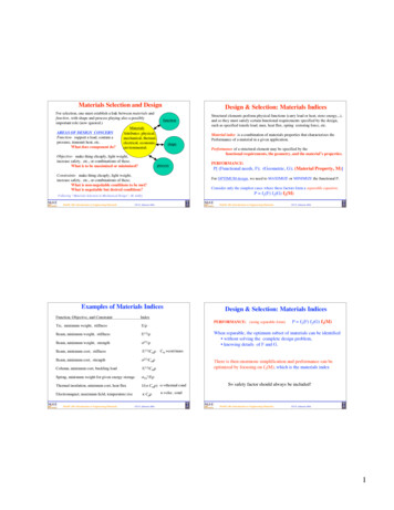
m AL (1)If the applied force on the connecting rod is ‘F’ and the endurance limit of the material as ‘ e’, the fatigueconstraint requires that,F / A e(2)The mass from equation (1) by eliminating ‘A’ is then given by,m FL( ) e(3)In order that the mass is minimized we need to maximize the material index, ‘M’:M1 e (4)Creating a chart with „ e‟ and „ ‟ as axes and applying an additional constraint that the fracture toughnessexceeds 15 MPa m identify materials with high values of this index. This is the selection process fordirect tension or compression load on the connecting rod. The selection is shown in Figure 1 and uses theLevel 2 Materials Universe of CES EduPack software.Figure 1: Fatigue Strength vs. DensityPage 15.1057.4From Figure 1 a number of candidate materials emerge. The prominent one is low alloy steelwhich is extensively used as the connecting rod material for engines running at high rotationalspeeds.
IMPACT OF SECTION SHAPEThe shape of the cross section plays a very important role in carrying loads, especially bending andtorsion. The shape can be optimized to maximize performance for a given loading condition. Simplecross-sectional geometries are not always optimal. For example, I-beams can carry bending loads moreefficiently when compared to a solid cross-section, like a solid square. By efficiency we mean for a givenloading condition the section uses as little material as possible.We define the shape factor in bending, „ B eeB’due to stiffness effects as:SSo(5)Here ‘S’ is the stiffness of cross section under consideration, and ‘So’ is the stiffness of reference solidsquare cross-section. It should be noted here that the bending stiffness ‘S’ is proportional to ‘EI’, where‘E’ is the elastic modulus and ‘I’ is the area moment of inertia. Noting that for a square of side ‘b’ wehave, comparing sections of same area, A,Io B eb 4 A2 12 12(6)SEI 12 I 2So EI oA(7)The shape efficiency as determined by the shape factor „ Be’, is dependent on the material, with theconstraints appearing from the considerations of manufacturing, material properties and local buckling.The maximum value for structural steels can be as high as 65.The other shape factor relates the strength-efficiency of the shaped beam, and is measured by the ratio ofthe section moduli as B fZZo(8)Where Zo is the section modulus of a reference beam of square cross section with the same cross-sectionalarea, Ab 3 A3 / 2Zo 66(9)Thus: B f6ZZ 3/ 2Zo A(10)e)if the limiting moment Me isPage 15.1057.5The failure of the connecting rod (stress exceeding the endurance limit,reached, that is when,
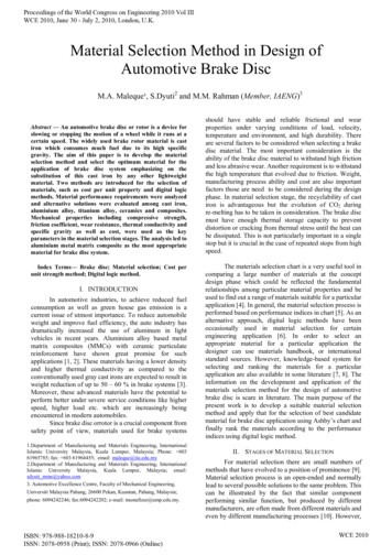
M e Z e(11)Replacing Z by expressions in equations (8) and (9) we have, M e B e A3 / 26f(12)Substituting A into the equation (1) for mass of the connecting rod, we have,m (6 M e )2/3 3/ 2 L f B e 2/3(13)The best material and shape combination (using maximum bending strength as a criterion) is that with thegreatest value of the new index M2 , where( B e ) 2 / 3fM2 (14)Similarly, the best material and shape combination (using maximum stiffness as a criterion) is that withthe greatest value of the new index M3, where( B E ) 1 / 2eM3 (15)CALCULATION OF SHAPE FACTORSFigure 2: Connecting Rod Rectangular and I-Beam Cross-SectionsWith the assumed shape of the cross section for the connecting rod as shown in Figure 2(b), thecross sectional area of the I-beam section is 11 t2.Ilia et al (2005) provide the minimum I-beam area for the connecting rod for the 1.9 L and 2.2 Lengines as 132 mm2 and 141 mm2 respectively. This gives the minimum thickness of the orderof 3.5 mm. Using 3.5 mm as the thickness dimension,A 11 (3.5)2 134.75 mm2(16)Page 15.1057.6The baseline area, A
The moment of area about the x-x axis, II 4t.t 3 t (3t ) 3 2 (t.4t )(2t ) 2 34.917t 4 5240mm412 12 (17)The section modulus, Z is given by,Z II34.917t 4 139.67t 3 2096mm3c (2.5t )(2.5t )(18)The stiffness related shape factor in bending is given from equation (7) by,12 I 12(5240) 3.46A2 (134.75) 2 B e(19)The strength related shape factor in bending from equation (10) is given by B f6ZA3 / 2 6(2096) 8.04(134.75) 3 / 2(20)COSELECTION OF MATERIAL AND SHAPEMaterial selection based on strength at a minimum weight is based on rewriting the materialindex for failure in bending from equation (14) as:( B e ) 2 / 3fM2 f f B 2 2/3 f 2 *f *2/3(21)BThe material with strengthof strength and density, *f fand density when shaped behaves in bending like a new material f f 2Band * f 2(22)BPage 15.1057.7
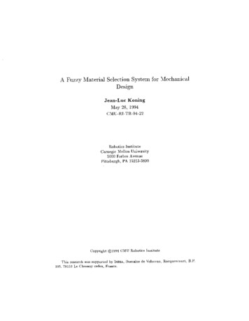
Material selection based on stiffness at a minimum weight is based on rewriting the materialindex for failure in bending from equation (15) as:( B E )eM3 1/ 2 E 1/ 2e B E * * (21) BThe material with modulus E and density when shaped behaves in bending like a new materialof modulus and density,E* eEe Band * e B(22)The co-selections based on minimizing mass for maximum strength and for maximum stiffnessare shown in Figures 3 and 4 respectively. The Level 2 Materials Universe of the CES EduPacksoftware is used for this purpose.Figure 3 Tensile Strength vs. DensityPage 15.1057.8
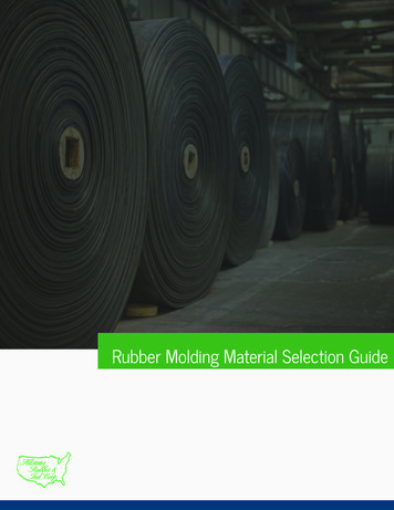
Figure 4 Young’s Modulus vs. DensityFigures 3 and 4 clearly show the effect of the section shape on the overall performance instrength and stiffness respectively. The strength of the material based on the choice of mediumcarbon steel shows improved performance with a fictitious material whose tensile strength aswell as density are (1/65) of that of the medium carbon steel, as shown in Figure 3. The stiffnessof the material based on the choice of low alloy steel shows improved performance for afictitious material whose elastic modulus as well as density are (1/3.46) of that of low alloy steel,as shown in Figure 4.SELECTION OF MANUFACTURING PROCESSAccording to Ilia et al (2005), the weight of connecting rod for 1.9L engine is 545 gm, and thatfor a 2.2 L engine is 544 gm. The minimum section is about 3.5 mm. Dimensional precision isimportant so that the clearances at the crankshaft end and at the piston end are assured. A lowersurface roughness is necessary so as to minimize surface crack initiation. The followingparameters are inputted into the CES EduPack code using the Level 2 Process Universe. Thedetails are shown n Table 1.Page 15.1057.9
TABLE 1 Comparison of Manufacturing ProcessesConstraintsFunctionObjectiveConnecting RodMinimize costConstraintsMaterial: Medium Carbon SteelShape: 3D SolidMass: 0.545 kgMinimum section: 3.5 mmTechnicalTechnicalTechnicalTechnicalTolerance: 0.25 mm (surface)Tolerance: 0.02 mm (bores)Roughness: 5 mQualityQualityQualityBatch size: 10 000EconomicThe processes that evolve are forging, die casting and pressing / sintering (powder methods).For both fracture-split drop forging and fracture-split powder forging, one piece forging uses acap that is broken off (fracture-split) the main part of the connecting rod. The drop forgingprocess uses C-70 crackable forging steel. Alloying elements in this material enable hardeningof the forged connecting rods when they undergo controlled cooling after forging. While the twocompeting forging processes are similar, there are subtle differences between two. The forgedsteel connecting rod is fabricated by starting with a wrought steel billet, heating and forging it inthe material‟s plastic temperature range, fractur
sophomore level Mechanical Engineering curriculum. A connecting rod is one of the most mechanically stressed components in internal combustion engines. The objective of the activity is to select the appropriate material for a connecting rod where the constraints are to make the product as light and cheap as possible and yet strong enough to carry the peak load without failure in high cycle .