Transcription
RESOURCE GUIDEP r o d u c tM a n u a l The information contained in this Resource Guide along with additional maintenance and repair information,videos and photos can be found online at www.STARTinternational.com START International
CONTENTSRead this resource guide before operating to ensure proper operation. Keep this resourceguide on hand for future reference.Warranty Information . . . . . . . . . . . . . . . . . . . . . . . . . . . . . . . . . . . . . . . . . . . . . . . . . . . . 2Notes . . . . . . . . . . . . . . . . . . . . . . . . . . . . . . . . . . . . . . . . . . . . . . . . . . . . . . . . . . . . . . . . 3Features . . . . . . . . . . . . . . . . . . . . . . . . . . . . . . . . . . . . . . . . . . . . . . . . . . . . . . . . . . . . . . 3Description of Parts and Functions. . . . . . . . . . . . . . . . . . . . . . . . . . . . . . . . . . . . . . . . . . . 4Operation. . . . . . . . . . . . . . . . . . . . . . . . . . . . . . . . . . . . . . . . . . . . . . . . . . . . . . . . . . . 5-6Precautions. . . . . . . . . . . . . . . . . . . . . . . . . . . . . . . . . . . . . . . . . . . . . . . . . . . . . . . . . . . . 6Specifications . . . . . . . . . . . . . . . . . . . . . . . . . . . . . . . . . . . . . . . . . . . . . . . . . . . . . . . . . . 7Troubleshooting. . . . . . . . . . . . . . . . . . . . . . . . . . . . . . . . . . . . . . . . . . . . . . . . . . . . . . . . . 7Preventive Maintenance . . . . . . . . . . . . . . . . . . . . . . . . . . . . . . . . . . . . . . . . . . . . . . . . . . 8Additional Information for ZCM2000. . . . . . . . . . . . . . . . . . . . . . . . . . . . . . . . . . . . . . . . . 8Exploded Views/Parts Breakdown. . . . . . . . . . . . . . . . . . . . . . . . . . . . . . . . . . . . . . . . .9-14Parts List. . . . . . . . . . . . . . . . . . . . . . . . . . . . . . . . . . . . . . . . . . . . . . . . . . . . . . . . . . 15-23WARRANTY POLICY for zcm series tape dispensersSTART International warrants all parts on ZCM series tape dis pens ers against defects in design, materials andwork man ship for a period of 180 days. Parts excluded from this are: cutting blades, sil i cone rollers and cutterliners; these parts are considered “wear parts”. Labor to replace defective parts will be per formed at no chargefor the first 90 days after date of purchase. Warranty does not cover transportation costs.START International’s sole obligation under this warranty is limited to repair, replacement or credit of thepurchase price, at our option, which do not prop er ly perform the function for which they were designed.Warranty repair is contingent upon START’s examination and de ter mi na tion that al legedde fects have not been caused by misuse, abuse, improper in stal la tion or application, re pair, alteration, accidentor neglect in use, storage, trans por ta tion or handling.The above warranty and remedy constitutes START International’s sole liability hereunder and are in lieu andexclusive of all other warranties and remedies expressed, implied, or statutory, in clud ing, but not limited to, thoseof merchantability and fitness for a par tic u lar purpose.REPAIR POLICYContact START INTERNATIONAL to determine nature of prob lem.Furnish START with the following information:1. Who the unit was purchased from.2. Model number and serial number.3. Date purchased (copy of invoice or packing slip required).START will issue an RMA (Return Material Authorization) for the repair. Return machine toSTART by freight, insured and pre paid. START will notify the customer if there is a repair charge.A 25.00 evaluation charge will apply to all non-warranty repairs, which will be applied torepair change.For the full Warranty & Repair policy please visit www.STARTinternational.com2
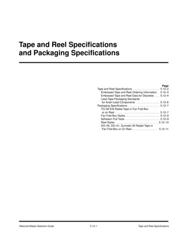
NotesDo not leave the tape dispenserin direct sunlight.Do not drop the tape dispenseror subject it to heavy shocks.Do not use volatile liquids(thinner, benzine, etc.) to cleanthe dispenser. Wipe with drycloth only.Do not use the tape dispenser inhumid or dusty places.Do not insert bars or platesinto the tape outlet – this willdamage the blade.Do not insert your fingers intothe cutting head!FEATURES If using automatic feed, when one piece of tape is removed the unit will automatically feedand cut the next piece at the preset length. The tape length is easily seen on the LED display, and op er a tion is simple — press the cmkey or mm key to set the length (Setting limit: 20mm to 999mm). If a piece of long tape is needed, press ADVANCE key for desired length, then press CUT keyto cut. The blade unit can be removed and replaced easily. (Tape jamming is also easily fixed byremoving the blade unit.)3 START International
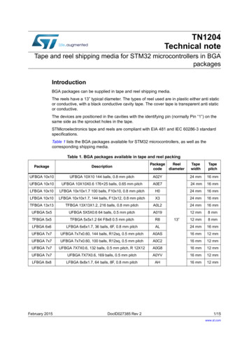
DESCRIPTION OF PARTS AND FUNC TIONSTape Length DisplayLENGTH ADJUSTMENT KeysReset KeyReverse KeyReelCut KeyPressureKnobADVANCE KeyADVANCE / CUT KeyCutterLatchAUTO Sensor SwitchSensor PlugFuseFeedRollerSeparatingRollerPower Switchtape length Power SwitchPress to turn powerON or OFF. Reverse KeyFeed Roller reverses.Use this key to change tape. Tape Length DisplayThe last digit indicatesmil li me ters and the first twodigits centimeters. ADVANCE KeyTape dispenses as long askey is pressed. LENGTH ADJUSTMENT KeysPress mm key to set tapelength in mm. Press cm keyto set tape length in cm. Reset KeyLength display is reset to20mm. This key can beused as an emergency stop. Cut KeyPress to cut tape.ADVANCE / CUT ADVANCE / CUT Key Pressure KnobAdjusts top roller to changepressure on tape.Feeds tape to the presetlength and cutsautomatically.4
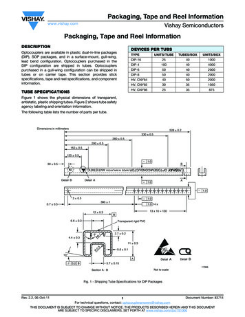
operationUsing Automatic Feed:1. Plug in power cord and turn unit on.2. Set tape on the center of reel and stick the end of the tape onto the metal feed roller.Press ADVANCE key until tape feeds through cutting unit. If the tape will not feed throughthe cutter, fold corners of the tape to form a triangle shape and re-feed (Fig. A).3. Press CUT key to cut tape.4. Set the tape length.Press MM key to set length of 0-9mm.Press CM key to set length of 20-990 mm.FOLDTAPEBACKFIG. A5. Set PRESSURE knob If tape curls or slips, increase pressure. If tape creases, decrease pressure.6. Turn sensor switch ON. Tape will be fed to set length and cut. When the piece of tape isremoved from machine, another piece will be fed and cut. (Turn sensor switch OFF whennot in use.)Using ADVANCE / CUT keyWith AUTO SENSOR switch OFF, press ADVANCE / CUT key. Tape will be fed to set length andcut.Using ADVANCE keyPress ADVANCE key until desired tape length has been fed. (This key overrides the presetlength.) Press cut to cut tape.Changing tapePress the REVERSE key. The feed roller will rewind the tape away from cutter area. Removethe tape manually.In case of tape jamPress REVERSE key to remove tape from cutter area. Rewind and replace tape on roller.Also, remove cutter unit to verify no tape is stuck on roller or cutter.5 START International
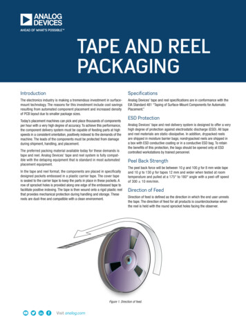
operation (CONT'D)To Replace Cutter UnitTurn off auto sensor and power before removing cutter unit. Pull sensor plug out, then pullcutter unit forward while pressing the knob on the top of the unit(Fig. 1).To replace blades, remove the two screws inside head. Bladecan then be lifted out and replaced. Before re mount ing thecutter unit to the frame, the lower blade must be bot tomedout. If it is not completely down, use a screw driv er to lower it(Fig. 2).Remount the cutter unit by aligning the bottom of the unitthen push ing in the top.Replacing the Separating RollerTurn off the sensor and power before re mov ing the separatingroller. Remove the cutter unit, then remove the two screws(Fig. 3).To remove roller holder, grip rubber ring in thecenter of separating roller and pull. Then re movethe screws on the left and right of the roller holder and pulloff shaft and gear (Fig. 4).KNOBFIG. 1LOW ERBLADEFIG. 2FIG. 3ROLLER HOLDERGEARSHAFTFIG. 4precautions Set the tape properly as described in these instructions. (If the end of the tapeis folded when the tape is set, the tape may jam at the tape outlet.) This machine will cut virtually any type of pressure sensitive tape (alu mi num,filament, etc.). If tape is thicker than .05" or thinner than .03”, test for com pat i bil i ty. Because of tape differences (elasticity, stickiness, etc.), some tapes may notcut at the set length. If this occurs, adjust the set length ac cord ing ly. If tape sticks to the blade, remove the cutter unit, clean with alcohol andapply sil i cone oil to the blade. To reduce jamming, remove tape from machine when not in use.6
specificationsModelzcM1000DisplayApplicable Tape Width.28” - 2” (7 - 50mm)Core Diameter3” (optional 1”, 1.25”, 1.5”)Tape Length Set Limit.79” - 39” (20-999mm) .040”Memory SettingsDrivezcM20003-Digit LED13DC Motor for Tape Advancement and Tape CutPower Consumption18WPower (AC)117V 50/60Hz or 230V 50/60HzAmbient Temperature41º - 104ºF (5º - 40ºC)Ambient HumidityLess than 80% RHDimensions5.4 x 8.6 x 6” (14 x 22 x 15cm)Weight5.3 lbs (2.4 kg)troubleshootingWhen problems occur, carry out the following procedures. If the tape dis pens er does notoperate normally after following the troubleshooting pro ce dures, contact your supplier.1. If the motor does not drive: Check that the power cord is plugged in. Check that the power switch is turned on.2. If the tape does not cut: Make sure the cutter unit is set properly and clean.3. If the LED does not light: Check that the power cord is plugged in. Check that the power switch is turned on.4. If the tape does not advance: Check if the tape is jammed at the roller or in the cutter unit. Check that the tape is set properly.5. If the auto sensor does not work: Check that the sensor plug is plugged in. Check that the sensor switch of cutter unit is on. Check that the sensor part of the cutter unit is not stained.6. If the tape advancing does not stop: Check that the tape is centered. If not, set the tape at the center of thefeed roller so that the sensor will see the tape.7 START International
PREVENTIVE MAINTENANCEWEEKLY MONTHLY-Remove cutting head. Clean and look for missing roller rings. Re placeas needed.Remove blade spring and blades to inspect cutter liners. Place onedrop of silicone oil on each liner, or replace if worn. Inspect feed rollerand blades for tape fragments or ad he sive buildup. Clean with alcohol.Additional information for zcm2000MEMORY KeyThe reverse key on the ZCM1000 is changed to the MEMORY (M) keyon the ZCM2000. (The reverse function can be accessed by press ing the FEED keyand the M key at the same time. This function is for changing tape.)Setting Memories1. Press and hold the M key until the LED display flashes.2. Using the cm and mm keys, set the desired length for first cut.A. The mm key controls the millimeter setting (1 digit).B. The cm key controls the centimeter setting (2 digits).(Ex: 125mm 12cm and 5mm.)C. Press M key to record memory. (The display will then flash “999”.)3. Set additional lengths as shown in #2. (If only two lengths are needed,record “999” as last length — “999” length will not be memorized.)4. After lengths are set, the display will flash “0”.Press mm key to switch between “0” and “5”: On “0”, the machine will feed and cut the first set length until theM key is pressed, then it will feed the second length until the Mkey is pressed, and so on. On “5”, the machine will feed and cut the recorded lengths inseries.5. When set correctly, press and hold the M key until the display stops flashing. Thefirst preset length will be shown on the display and the unit is ready to use.6. Programmed tape lengths will be fed and cut in order when using either thesensor unit automatic feed and cut or the ADVANCE / CUT button.7. If RESET (20) key is pressed, all of the memory will be erased.8
exploded views / parts break downREMOVE BODY COVER AND BOTTOM PLATE550-1550S200-1560-1CHANGE THE SEPARATING ROLLERNumbers in balloons 100 represent the last digits in re place ment part number.When ordering, ask for ZCM1000P9 START International
exploded views / parts break downFRONT HOLDER STRUCTUREFRONT HOLDER 3 UNITNumbers in balloons 100 represent the last digits in re place ment part number.When ordering, ask for ZCM1000P10
exploded views / parts break downFEED STRUCTUREBearing - 2REMOVING SENSOR UNIT560-1Numbers in balloons 100 represent the last digits in re place ment part number.When ordering, ask for ZCM1000P11 START International
exploded views / parts break downNOTE: Parts grouped within broken lines can be purchased as complete assemblies.SPPSNumbers in balloons 100 represent the last digits in re place ment part number.When ordering, ask for ZCM1000P12
Corresponding Parts:ZCM1000 ZCM2000102. 605251. 612504. 601BPPSThe information contained in this Resource Guide along with additional maintenance and repair information,videos and photos can be found online at www.STARTinternational.com13 START International
exploded views / parts break downBOTTOM PLATE WIRING117V230V230VCONTROL PANEL CONNECTIONSNumbers in balloons 100 represent the last digits in re place ment part number.When ordering, ask for ZCM1000P14
Part #Part NameIllustrationzcM1000P101Body coverStandard PartzcM1000P102Panel coverStandard PartzcM1000P105LED coverStandard PartzcM1000P106Pressure KnobStandard PartzcM1000P107BCore holderStandard PartzcM1000P111Transformer117VStandard Part(on 117 Volt Machines)zcM1000P112Transformer230V(CE)Standard Part(on 230 Volt Machines)zcM1000P113Screw (4* 8)Standard Part(To hold transformeron base)zcM1000P114Nut with washerStandard Part (4mm)zcM1000P115BaseStandard PartzcM1000P116Rubber feetStandard Part15Notes START International
Part #Part NameIllustrationzcM1000P118Power switchStandard PartzcM1000P120Fuse (1A)Standard PartzcM1000P121Fuse holderStandard PartzcM1000P124Center frameStandard PartzcM1000P136Separating rollerunitStandard Part(Used with P138)zcM1000P138Separating rollerringStandard Pa
If the tape dispenser does not operate normally after following the troubleshooting procedures, contact your supplier. 1. If the motor does not drive: Check that the power cord is plugged in. Check that the power switch is turned on. 2. If the tape does not cut: Mak e sure the cutter unit is set properly and clean. 3. If the LED does not light: Check that the power cord .