Transcription
Int. J. Nav. Archit. Ocean Eng. (2013) 5:598 : 2092-6782, eISSN: 2092-6790 SNAK, 2013An optimum design of on-bottom stability ofoffshore pipelines on soft claySu Young Yu1, Han Suk Choi1, Seung Keon Lee2, Chang Ho Do3 and Do Kyun Kim11Graduate School of Engineering Mastership, Pohang University of Science and Technology, Pohang, Korea2Department of Naval Architecture and Ocean Engineering, Pusan National University, Busan, Korea3Hyundai Heavy Industries, Co., Ltd., Ulsan, KoreaABSTRACT: This paper deals with the dynamic effect of pipeline installation and embedment for the on-bottom stability design of offshore pipelines on soft clay. On-bottom stability analysis of offshore pipelines on soft clay by DNV-RPF109 (DNV, 2010) results in very unreasonable pipe embedment and concrete coating thickness. Thus, a new procedureof the on-bottom stability analysis was established considering dynamic effects of pipeline installation and pipe-soilinteraction at touchdown point (TDP). This analysis procedure is composed of three steps: global pipeline installationanalysis, local analysis at TDP, modified on-bottom stability analysis using DNV-RP-F109. Data obtained from thedynamic pipeline installation analysis were utilized for the finite element analysis (FEA) of the pipeline embedmentusing the non-linear soil property. From the analysis results of the proposed procedure, an optimum design of onbottom stability of offshore pipeline on soft clay can be achieved. This procedure and result will be useful to assess theon-bottom stability analysis of offshore pipelines on soft clay. The analysis results were justified by an offshore field inspection.KEY WORDS: On-bottom stability; Offshore pipeline; Dynamic effect; Soft clay; Pipeline embedment.INTRODUCTIONInterest on offshore energy resources has been increasing globally, especially in Brazil, India, China, and other developingcountries. The marine world in 2030 will be almost unrecognizable owing to the rise of emerging countries as mentioned, newconsumer classes and resource demand (Fang et al., 2013). As development activities for energy demand move to deepwater,many offshore pipelines to transport oil and gas will be installed. The clay soil on seabed below installed pipelines ranges fromvery soft to very stiff soil. This paper deals with soft and very soft clay soil and the pipelines will be embeded further into thesoft soil. The exact behavior between a pipeline and soil is not known. The heaved soil and resistance forces are hence important aspects. It is important to properly model pipe-soil interaction effects (Bai and Bai, 2005). Pipe embedment depth by pipesoil interaction has become critical design parameter to design offshore pipeline such as free span and thermal expansion as wellas on-bottom stability. On-bottom stability analysis that a pipeline maintains stability on seabed against hydrodynamic load ofwave and current has to be considered with a relevant pipe-soil interaction analysis.The pipelines are under the combined loads such as bending, axial force, and external pressure during installation due to theCorresponding author: Han Suk Choi, e-mail: hchoi@postech.ac.krThis is an Open-Access article distributed under the terms of the Creative CommonsAttribution Non-Commercial License ch permits unrestricted non-commercial use, distribution, and reproduction in anymedium, provided the original work is properly cited.
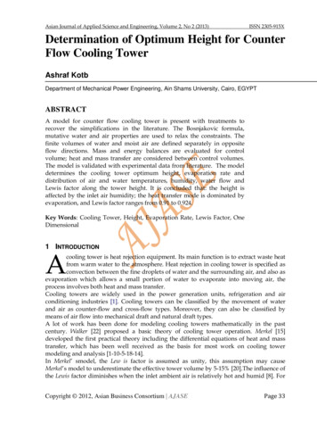
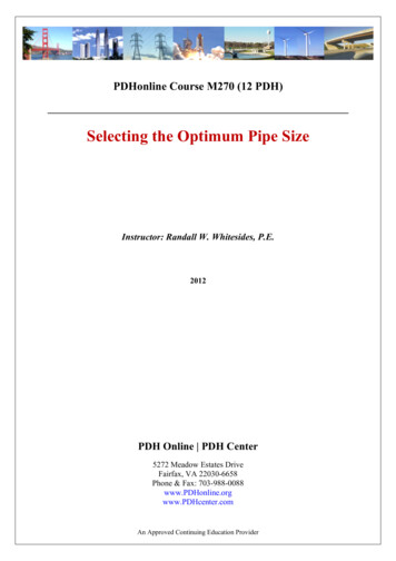
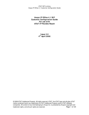
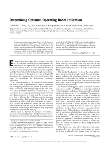
Int. J. Naval Archit. Ocean Eng. (2013) 5:598 613599dynamic vessel motion. At TDP, the seabed disturbance will occur by the dynamic pipe-soil interaction. A typical s-lay configuration and applied pipeline loading during installation is presented in Fig. 1.Studies on pipe-soil interaction and assessing penetration depth have been progressing lately. Verley and Lund (1995)developed pipe-soil interaction models on clay soils considering penetration effects of pipe subjected to oscillatory forces inwaves based on model test data and this formula was adapted in DNV-RP-F109. White and Cheuk (2008) studied soil resistance on seabed pipelines during large cycles of the lateral movement for realistic soil behaviors. Randolph and White (2008b)and Merifield et al. (2009) present pushed-in-place (PIP), taking into account of combining the vertical and horizontal loadingusing a heaved soil model. Before these studies, the model based on wished-in-place (WIP) considering relations only betweenthe vertical load and normalized pipe penetration was used. The WIP and PIP models are illustrated in Fig. 2.Lay vesselTensionerStingerqMC: compression forceM: bending momentq: stinger reactionT: tensionTOverbendTMqqCSagbendTouch down point (TDP)Fig. 1 Typical s-lay configuration and applied pipeline loading during installation.The environmental loads on the embedded pipelines are reduced on soft clay. If an exact initial penetration depth can becalculated, an optimized required submerged weight can be derived easily. Currently, no methodology has developed considering simultaneously both of the dynamic pipeline installation and the pipe embedment at TDP. Thus a new proposed procedure was developed in this study. The details of the procedure are described in the next chapter.In this study, the recent trend for the on-bottom stability analysis was investigated and a case study was performed using theproposed new procedure. Analysis results between seabed penetration depths with dynamic effect and without dynamic effectwere compared.(a) WIP.(b) PIP.Fig. 2 Schematic of wished-in-place (WIP) and pushed-in-place (PIP).
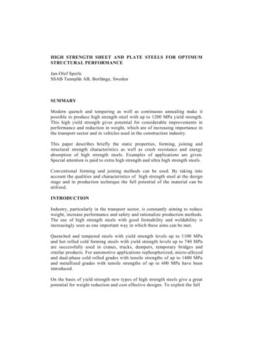
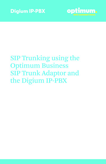
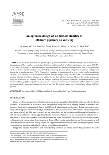
600Int. J. Naval Archit. Ocean Eng. (2013) 5:598 613A NEW PROCEDURE OF ON-BOTTOM STABILITY ANALYSISFig. 3 shows the proposed new procedure for the on-bottom stability with dynamic effect of offshore pipeline installation.The analysis procedures are made up three steps such as global pipelay analysis, simulation of dynamic local pipeline embedment at the TDP, and modified on-bottom stability design. Details on each step are described in the subchapters. The timehistories of horizontal displacement and vertical soil resistance at TDP are calculated through global pipelay analysis using pipeproperties, environmental data, and others. The time histories of horizontal displacement and vertical soil resistance were usedfor input of local pipe-soil interaction analysis with a finite element method (FEM). The maximum value among pipe embedment depths by local dynamic analysis was used for an initial penetration depth, the modified on-bottom stability analysis basedon DNV-RP-F109. The calculation result based on design codes considering the dynamic penetration depth from FEA can beused for an optimum on-bottom stability design.1st input data1st output dataStructural dataEnvironmental dataOthersDesign codeGlobalinstallation analysis(Dynamic analysis)Time-history of pipehorizontal displacementTime-history of verticalsoil resistanceDNV-OS-F101API RP 11112nd output data2nd input dataLocal analysis at TDPSoil data(Dynamic embedmentanalysis)Pipe dataTime-history of pipeembedmentOthersDesign codesDNV-RP-F109DNV-RP-E305Modified on-bottomstability analysisFig. 3 Proposed new procedure for on-bottom stability analysis.Global installation analysisThe commercial pipeline installation programs are based on FEA and calculated the stress, strain, touchdown length, departure angle, and soil reaction force at TDP. Installation method of the s-lay was used for the present study. General procedure anddetails of the global analysis are summarized in Fig. 4. The DNV-OS-F101 (DNV, 2012) for design criteria was used to checkthe allowable stress and strain. The OFFPIPE software as an analysis tool was used in this study. The background of OFFPIPEsoftware could be referred to OFFPIPE manual (OFFPIPE, 2013).The environmental input data include waves, currents, water depth, and soil shear strength, submerged weight of soil, andfriction coefficient. The lay vessel information incorporates hull dimension, locations of rollers and tensioners, configuration ofstinger, and vessel response amplitude operator (RAO). The installation analysis was divided into two steps: static and dynamicanalyses. Important parameters in this analysis are summarized in Table 1. Results by static analysis were checked with designcriteria and then dynamic analysis was performed. Time histories of horizontal displacement and vertical soil resistance wereobtained by the dynamic pipelay analysis.Table 1 Global installation analysis parameters from OFFPIPE.Static analysisParameters- Tensioner capacity- Strain/Stress at overbend and sagbendDynamic analysis- Horizontal displacement- Vertical soil resistance
Int. J. Naval Archit. Ocean Eng. (2013) 5:598 613DNV-OS-F101API RP 1111601OffpipeAnalysis toolsDesign codeOrcaFlexPipeLayOthersGlobal installation analysisInput data(Structural part)Input data(Environmental part)(Dynamic analysis)PipeCoatingLay vesselMetocean data Cross section(OD, WT) Materials Others Corrosion Concrete Field joint Others Hull dimensions Roller & Tensioner Vessel motion RAO Stinger and others Significant wave height Peak period Water depth Current velocity Wind & Tidal velocity OthersOutput dataTime-history of pipehorizontal displacementGeophysical data Soil types Shear strength Submerged weight Friction coefficient Nonlinear properties OthersTime-history of verticalsoil resistanceFig. 4 Global installation analysis of offshore pipelines.Local analysis at TDPThe purpose of the local analysis is to estimate initial pipe embedment depth considering the dynamic loads from globalpipelay analysis. The procedure of local analysis is illustrated in Fig. 5.The most important information to obtain pipe embedment depth by local analysis is soil data of seabed. Data such as shearstrength, Young’s modulus, and Poisson’s ratio for soft clay should be entered exactly though in-situ testing. Plastic propertiessuch as sensitivity and soil ductility are also important. There are FEA tools such as Abaqus and ANSYS for the pipe-soil interactions. Elastic perfectly plastic soil models including Mohr-Coulomb, Tresca, and von-Mises criteria and elasto-plastic soilmodel including modified Cam clay are used for many geo-engineering problems.Recently, researches on pipe-soil interaction behavior have been conducted actively and many constitute equations whichare expressed mathematically about stress-strain relation, initial yield strength, hardening, and softening on soil behavior arebeing developed. For example, Tresca criteria with the strain-softening was used for the pipe-soil interaction analysis andresearch work including tests was actively performed by Einav and Randolph (2005), Zhou and Randolph (2007), Wang et al.(2009), Chatterjee et al. (2010) and many others.Analysis toolAbaqusANSYSOthersInput data fromglobal analysisLocal analysis at TDP(Dynamic embedment analysis)Applied loadings Vertical force (Self weight)at center of mass Time-history of pipehorizontal displacement OthersAdditional input datafor soil & pipeConstitutive equations Plasticity theory Material property OthersOutput dataTime-history of pipeembedmentFig. 5 Local analysis at TDP of offshore pipelines.Compatibility conditions Boundary condition Geometry Others
602Int. J. Naval Archit. Ocean Eng. (2013) 5:598 613The empirical expression of shear strength for tresca constitutive model with exponential strain softening relationship is asfollow (Zhou and Randolph, 2007; Wang et al., 2009).(1)S u [δ rem (1 δ rem ) e 3ξ / ξ 95 ] S u 0where,Su 0 k zδ rem St ξ ξ 95 Intact undraind shear strength, ( Sum k z );Strength gradient;Soil depth;Fully remoulded strength ratio, ( 1 / S t );Sensitivity;Accumulated absolute plastic shear strain;Cumulative absolute shear strain required to cause 95 % reduction.Modified on-bottom stability analysisThe design procedure of modified on-bottom stability is presented in Fig. 6. General environmental data for each conditionare selected as follows (Guo et al., 2004). Installation condition: empty pipes with 1-year period environment Operation condition: product filled pipes with 10-years or 100-years period environmentDNV-RP-F109DNV-RP-E305AGA/PRCIAnalysis toolsDesign codeStableLinesOthersModified on-bottomstability analysisInput data from localanalysisPipe embedment depthAdditionalinput data Pipe (OD, WT, material, etc.) Environment (WD, wave, etc.) Soil (Shear strength, friction, etc.)Output dataConcretethicknessRequiredsubmerged weightDesign criteriacheckFig. 6 Modified on-bottom stability analysis of offshore pipelines.A design of on-bottom stability was performed according to following. Firstly, environmental criteria for the 1-year, 10years and 100-years conditions, including water depth, wave spectrum, current characteristics, and soil properties were defined.Hydrodynamic coefficients: drag (CD), lift (CL), and inertia (CI) which are adjusted with Reynolds numbers, Keulegan-Carpenter numbers, ratio of wave and the steady current, and embedment were determined. Hydrodynamic forces, typically, drag(FD), lift (FL), and inertia (FI) was calculated. Lastly, static force balance at time step increments was performed to assess the onbottom stability. A concrete coating thickness for the worst combination of lift, drag, and inertial force was calculated (Guo etal., 2004). Above mentioned various forces are illustrated in Fig. 7.In this study, on-bottom stability analyses were performed based on the modified analysis and DNV-RP-F109. The detailson this design code are explained in chapter 3 of DNV-RP-F109.
Int. J. Naval Archit. Ocean Eng. (2013) 5:598 613603FliftFinertiaFdragWFfrictionFnormalFig. 7 Schematic of forces acting on offshore pipelines.A CASE STUDY ANALYSIS OF ON-BOTTOM STABILITYThe on-bottom stability analyses were performed based on above mentioned new procedure inc
On-bottom stability analysis of offshore pipelines on soft clay by DNV-RP-F109 (DNV, 2010) results in very unreasonable pipe embedment and concrete coating thickness. Thus, a new procedure of the on-bottom stability analysis was established considering dynamic effects of pipeline installation and pipe-soil interaction at touchdown point (TDP). This analysis procedure is composed of three steps .