Transcription
PDHonline Course M270 (12 PDH)Selecting the Optimum Pipe SizeInstructor: Randall W. Whitesides, P.E.2012PDH Online PDH Center5272 Meadow Estates DriveFairfax, VA 22030-6658Phone & Fax: 703-988-0088www.PDHonline.orgwww.PDHcenter.comAn Approved Continuing Education Provider
www.PDHcenter.comPDH Course M270www.PDHonline.orgSelecting the Optimum Pipe SizeCopyright 2008, 2015Randall W. Whitesides, P.E.IntroductionPipe, What is It?Without a doubt, one of the most efficient and natural simple machines has to be the pipe. Bydefinition it is a hollow cylinder of metal, wood, or other material, used for the conveyance ofwater, gas, steam, petroleum, and so forth. The pipe, as a conduit and means to transfer mass frompoint to point, was not invented, it evolved; the standard circular cross sectional geometry isexhibited even in blood vessels.Pipe is a ubiquitous product in the industrial, commercial, and residential industries. It isfabricated from a wide variety of materials - steel, copper, cast iron, concrete, and various plasticssuch as ABS, PVC, CPVC, polyethylene, and polybutylene, among others.Pipes are identified by nominal or trade names that are proximately related to the actualdiametral dimensions. It is common to identify pipes by inches using NPS or Nominal Pipe Size.Fortunately pipe size designation has been standardized. It is fabricated to nominal size with theoutside diameter of a given size remaining constant while changing wall thickness is reflected invarying inside diameter. The outside diameter of sizes up to 12 inch NPS are fractionally larger thanthe stated nominal size. The outside diameter of sizes 14 inch NPS and larger are equal to the statednominal size. Pipe wall thicknesses are specified by schedule number with 5 being the thinnest and160 be the thickest. An older designation scheme for pipe wall thickness which still enjoys popularusage indicates nominal weight. This labeling system is depicted in Table 1 on page 2. A moredetailed dimensional table for NPS pipe is provided in Table 13 on page 77.When was It Used?Clay pipes have been found in excavations dated as early as 4000 BCE. They were used inMesopotamia, the Indus Valley civilization, the Minoan civilization, and of course the RomanEmpire (which also used lead pipes).1 People have used pipes for thousands of years. Perhaps thefirst use was by ancient agriculturalists who diverted water from streams and rivers into their fields.Archeological evidence suggests that the Chinese used reed pipe for transporting water to desiredlocations as early as 2000 BCE.2Selecting the Optimum Pipe Size 2008, 2015 Randall W. Whitesides, CPE, PE1
www.PDHcenter.comPDH Course M270www.PDHonline.orgTABLE 1 Cross Reference of Pipe Wall Thickness DesignationsSchedule No.Weight ―ST―XS―――XXDescription―Light gaugeLight weight――Standard weight―Extra strong―――Double extra strongEarly American settlers knew nothing of lead or iron pipe - theyknew only to build with wood, the country's bounty. Water pipeswere made of bored-out logs, felled from hemlock or elm trees.The trees were cut into seven-to-nine-foot lengths, with trunksbeing 9-10 inches in diameter. The interior was drilled or boredwith steel augers. One end was rammed to form a conical shape, and logs were jammed together inseries, using a bituminous-like pitch or tar to seal the joints. Sometimes the logs would be split andhollowed out, put together, and connected with iron hoops. A gravity water system would be set-up,starting from a spring or stream on high ground, allowing water to flow downhill to the house orfarm. In the early 1700s, New York, as well as Boston, had constructed a wooden pipe system underthe roads, and sold water at street pumps or hydrants. Wooden pipes were common until the early1800s when the increased pressure required to pump water into rapidly expanding city streets beganto split the pipes. A change was made to iron. In 1804, Philadelphia earned the distinction as thefirst city in the world to adopt cast iron pipe for its water mains. It was also the first city in Americato build large scale waterworks as it drew upon the ample supply of the Schuykill River.3Early pipe size selection was simple. The original pipe fabricators/layers of old were for themost part, not concerned with determining optimum pipe sizes since mere timber availabilitydictated the diameters installed.Selecting the Optimum Pipe Size 2008, 2015 Randall W. Whitesides, CPE, PE2
www.PDHcenter.comPDH Course M270www.PDHonline.orgWhy is It Round?Aside from the use of the round tree by our predecessors dueto its natural availability, pipe with a circular cross section ispreferred over other geometric cross sections for a host ofreasons. A quick mathematical examination reveals that acircular cross section results in the least surface area per unitof volume. Surface area is important because it relatesdirectly to the amount of material required to fabricate the conduit, as well as the amount ofprotective coating or insulation required to cover it. The circular cross section is hydrodynamicallymore efficient than non-circular sections in that it presents less contact surface area for fluid frictionfor a given volumetric flow rate. Additionally, a curvilinear profile promotes a smooth flow pathdevoid of abrupt inside corners or pockets that promote localized fluidstagnation. Structurally, the curved shell produced by the circular pipe crosssection allows a multiplicity of alternative stress paths and gives the optimumform for transmission of many different load types. This holds true for bothinternal loads like pressure and external loads such as those produced by backfill material or internal vacuum conditions. The single curvature allows for asimple fabrication process and is very efficient in resisting loads. Pressures are resisted very well bythe in-plane behavior of a shell. Because this pressure difference is across a curved surface, a hoopof circumferential membrane stress is developed in the pipe wall.The Optimum Pipe SizeOptimum pipe size denotes the best pipe size. From a simplisticstandpoint, the best pipe size is obviously the smallest size thatwill accommodate the application at hand. From a realisticstandpoint, optimum pipe size can have many meanings withproper consideration of the application. Optimum can meaneconomically efficient over the life of a system. Optimum canmean, as in the case of sulfuric acid, the pipe size which wouldlimit the fluid velocity to a value which prevents pipe wallerosion in elbows which ultimately results in structural failure.Optimum can mean, as in the case of fluids with suspended solids, that pipe size which wouldproduce a predetermined fluid velocity which is known to sustain the solids in suspension.Selecting the Optimum Pipe Size 2008, 2015 Randall W. Whitesides, CPE, PE3
www.PDHcenter.comPDH Course M270www.PDHonline.orgToo often, optimum pipe size is confused to be limited to mean most economic pipe size.Moreover, in addition to meaning satisfactory and maybe the most economical, optimum pipe sizemeans that diameter which acts or produces the required effect with a minimum of waste andexpense. This size can be far from the most economic due to specific process restraints.Quick Reference Chart of Useful Pipe Size EquationsTo gain immediate benefit from this course, this section provides a summary chart of formulas fordetermining approximate pipe sizes. The chart is presented at this point, before embarking on adetailed treatment of incompressible versus compressible fluid flow, single versus two phase flowpatterns and the like. It offers quick access to formulas to estimate probable or target pipe sizes.This listing contains both rational and empirical equations that have evolved through industry’sexperience. They do not necessarily take into consideration possible mitigating parameters such aserosion, solids suspensions, or slug flow ramifications. These and other important considerations arecovered later in the course. The mathematical expressions which follow are combinations of bothsimplified distillations of rational parent equations as well as rules-of-thumb. A list of thenomenclature used in the formulas and equations is provided immediately following the quickreference table.In the interest of brevity, equation nomenclature and unitsof measure are not provided separately with each equation.The student is therefore encouraged to frequently review (orbetter still, print) the nomenclature listing of Table 3.Units of measure for a specific equation variable are generallyconstant between equations. The exception is the flow variable “Q”which can be either cubic feet per second (ft 3/sec) or gallons perminute (gal/min; gpm) depending on the need for unit consistencywithin the equation. Students are encouraged to conduct mentaldimensional analysis when viewing equations and worked examples.Selecting the Optimum Pipe Size 2008, 2015 Randall W. Whitesides, CPE, PE4
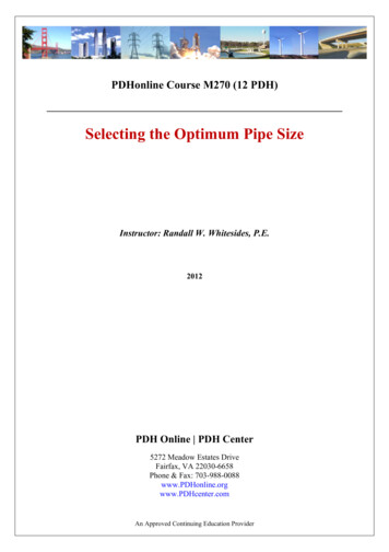
www.PDHcenter.comPDH Course M270www.PDHonline.orgTABLE 2 Quick Reference Summary Chart & Collection of Pipe Size Formulae(Important: refer to Table 3 Equation Nomenclature and Units)EXPLANATIONEQUATIONRANGE & LIMITATIONSPressurized Flow of LiquidsDarcy-Weisbachfrictional head loss 0.0311 f L Q2 d 12 hf Liquid general flowequationd 0.64Nominal pipe size fornon-viscous flow Q d 12. 0.2Q in gal/min.QVQ in gal/min.1/ 3 2Q 100 gal/mind 0.25 QQ 100 gal/minNominal pipe size fornon-viscous flowPump suction size tolimit frictional headlossPressurized Flow of Gasesd Gas general flowequationd 0.290.0744 QQ in gal/minQTPVQ in standard ft3/min; T in R; P inlb/in2 absolute.Gas general flowequation Q d 22 8306 P1 P2 GTLZ f Minimum diameter tolimit erosional gasflow ZTG d 0.001 Q P Weymouth gas flowequation W 2G L d 22 786.8 P1 P2 0.40.250.1876Isothermal fully turbulent flow; L inmiles; Q in standard ft3/day.Q in standard ft3/day; T in R; P inlb/in2 absolute.Isothermal fully turbulent flow; L inmiles.Two-Phase FlowRelief valve dischargeflashing flow W ZT M w d 408.245 M P Selecting the Optimum Pipe Size 2008, 2015 Randall W. Whitesides, CPE, PE0.5Isothermal flow of an ideal gas forselected Mach Number M.5
www.PDHcenter.comPDH Course M270EXPLANATIONwww.PDHonline.orgEQUATIONWgSuitable pipe size forgas/liquid flowd 0.2256RANGE & LIMITATIONS g VWl lWith known two-phase mixturevelocity V.Steam and VaporSteam & vaporgeneral flow equationd 175.Wvg xVGravity FlowManning formula formaximum flowQn d 1525S 0.375Manning formula forfull pipe flowQn d 1639S 0.375Minimum openingsize of self-ventingside entry overflowMinimum pipe size forself-venting verticalpipe flowBased on y d ; Q in ft3/sec.d 0.92Q 0.4 Q d 27.8 r 5/3 TABLE 3SymbolAAbCCCiCocDDPdFUfBased on y/d 0.983 ; Q in ft3/sec.Q in gal/min; 2 d 18; y/d 0.753/8Where r is ratio of annual flow area topipe cross sectional area; Q in gal/min.Equation Nomenclature and UnitsDefinitionCross sectional flow areaExponential correlation constantSettling velocity constantTotal costTotal life cycle cost present valueInitial or first costAnnual operating costMean volume fractionInside pipe diameterSolid particle diameterInside pipe diameterFixture UnitColebrook friction factorSelecting the Optimum Pipe Size 2008, 2015 Randall W. Whitesides, CPE, PEU.S. customaryunitsft2DimensionlessDimensionlessU.S. U.S. U.S. U.S. Decimal percentftiningal/minDimensionless6
www.PDHcenter.comPDH Course M270TABLE VSHvvgWWgWlxwww.PDHonline.orgEquation Nomenclature and Units (continued)DefinitionSpecific gravityGravitational constantEnergy input to overcome frictionAnnual cost escalation rateFroude numberCritical static headFrictional head lossSettling velocity constantLengthMach numberMolecular weightHindered settling exponentBreakeven timeReynolds numberUseful life of project alternativeManning friction factorSettling velocity constantPressureWetted perimeterGas-phase pressureLiquid-phase pressureVolumetric flow rateVolumetric flow rateHydraulic radiusRatio of annular flow areasSlope (hydraulic gradient)Saturated steam temperatureGas temperatureSystem annual operation timeMean fluid velocityMean fluid velocitySingle particle settling velocityHindered settling velocitySpecific volumeSaturated steam specific volumeWeight flow rateGas two phase weight flow rateLiquid two phase weight flow rateSteam qualitySelecting the Optimum Pipe Size 2008, 2015 Randall W. Whitesides, CPE, PEU.S. l percentDimensionlessinft of fluidDimensionlessftDimensionlesslbm t -1/3Dimensionlesslbf /in2ftlbf /in2lbf /in2ft3/secgal/minftDimensionlessDimensionless F Rhrft/secft/minft/secft/secft3/lbmft3/lbmlbm /hrlbm /hrlbm /hrDecimal fraction7
www.PDHcenter.comTABLE 3SymbolPDH Course M270www.PDHonline.orgEquation Nomenclature and Units (continued)DefinitionU.S. customaryunitsYgGas compressibility factorDimensionlessyLiquid flow ----------------------------------------Greek ----------------------------------------αPiping system alternative choiceDimensionlessβPiping system alternative choiceDimensionlessΔDifferential changeDimensionlessεPipe absolute roughnessftηmElectric motor efficiencyDecimal percentηpPump hydraulic efficiencyDecimal percentμAbsolute viscositycPυKinematic viscosityft2/secρFluid densitylbm /ft3ρFMixed phase fluid densitylbm /ft3ρPSolid particle densitylbm /ft3χMole fractionDecimal fractionWhen units other than those listed are used, it will be expressly notedat the time of equation presentation.Pipe Flow BasicsFlow RegimesDuring the 1880s an Irish Engineer and physicist named Osbourne Reynolds con
Suitable pipe size for gas/liquid flow d W W V g g l l 0.2256 With known two-phase mixture velocity V. Steam and Vapor Steam & vapor general flow equation d Wv x V 1.75 g Gravity Flow Manning formula for maximum flow d Qn S 1525 0.375 Based on y/d 0.983 ; Q in ft3/sec. Manning formula for full pipe flow d Qn S 1639 0.375File Size: 1MBPage Count: 81