Transcription
DECEMBER 2008 ICE STORMChapter IV - System Planning, Design, Construction, and ProtectionCHAPTER IVSystem Planning, Design, Construction, and ProtectionChapter StructureChapter IV.IV-1Chapter Structure .IV-1A.Background .IV-1Transmission and Distribution.IV-1Transmission System .IV-2Sub-Transmission System.IV-4Distribution System .IV-5Electric Distribution Substations .IV-7Transmission System Protection.IV-8Distribution System Protection .IV-9Substation Protection .IV-9SCADA .IV-10Covered Wire .IV-10Pole Construction and Loading.IV-11B.Evaluative Criteria.IV-12C.Tasks.IV-19D.Findings and Conclusions .IV-19A. BACKGROUNDTransmission and DistributionThe December 2008 ice storm caused extensive power outages throughout the state of NewHampshire. Since the backbone of any electric system involves the transmission system, areview was made of the transmission systems that support PSNH, Unitil, National Grid, andNHEC in order to ascertain how they were affected by the ice storm. In New Hampshire,transmission voltage levels begin at 69 kV. Voltages below 69 kV are typically categorized asdistribution.While states may have laws or regulations that influence the transmission system, the reliabilitycriteria for transmission systems are normally dictated by federal agencies such as the FederalEnergy Regulatory Commission (FERC) and the North American Electric ReliabilityCorporation (NERC). In most cases, transmission systems are designed, constructed, protected,and operated with higher utility industry standards than distribution systems. The reliabilitycriteria applicable to most transmission lines require that the loss of a single transmission lineNEI Electric Power EngineeringPage IV-1
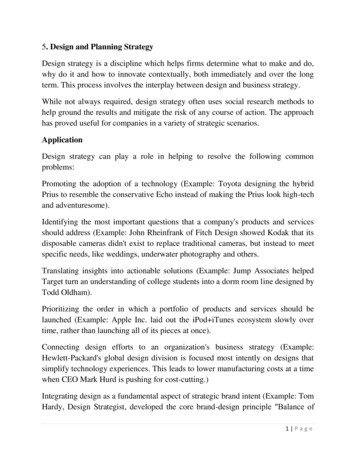
DECEMBER 2008 ICE STORMChapter IV - System Planning, Design, Construction, and Protectionwill not result in an outage to customers. Additional distinctions between the transmission anddistribution systems and the sub-transmission system are discussed below.Transmission SystemFigure IV-1 shows a modern 115 kV transmission line located in Manchester, New Hampshire.This figure shows a common double circuit with single steel pole construction. Note the contrastwith the traditional two-pole, H-Frame construction shown in Figure IV-2.Figure IV-1 - 115kV transmission line structures located near Mall of New Hampshire in Manchester. (Photoby NEI – PSNH System)NEI Electric Power EngineeringPage IV-2
DECEMBER 2008 ICE STORMChapter IV - System Planning, Design, Construction, and ProtectionFigure IV-2 - Common H-Frame transmission line construction. (Photo courtesy of NHPUC)Overhead transmission lines are typically placed on larger structures and elevated higher abovethe ground than common distribution circuits. Another distinction is that transmission lines willnormally have a large, well managed right-of-way (ROW). The vegetation management practicestypically followed for transmission lines commonly include the wire-zone border-zone practice,which requires clearing vegetation immediately under the conductors (wire-zone) and on eitherside of the conductors to the edge of the ROW (border-zone). The wire-zone border-zonepractice has been effectively endorsed by FERC and NERC.1In New Hampshire there are four commonly used transmission voltage levels: 115 kV ac2230 kV ac345 kV ac450 kV dc31“New Diagrams and Applications for the Wire Zone-Border Zone Approach to Vegetation Management onElectric Transmission Line Rights-of-Way.” Arboriculture & Urban Forestry, 33, (6), November 2007, pgs 435439.2ac – alternating current – The most widely used transmission, distribution and utilization voltage in NewHampshire and the United States.NEI Electric Power EngineeringPage IV-3
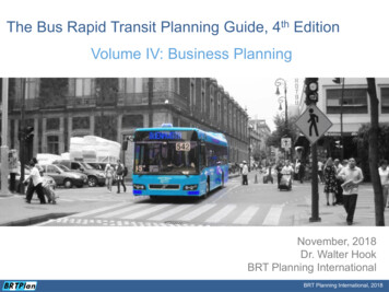
DECEMBER 2008 ICE STORMChapter IV - System Planning, Design, Construction, and ProtectionThe 115 kV voltage level is commonly used to deliver power to sub-transmission systems anddistribution substations. The 230 kV and 345 kV voltage levels are commonly used to deliverbulk power to transmission and sub-transmission substations. Systems operating at 450 kV dcare used to transfer bulk power through the state of New Hampshire and are not presently used todirectly serve loads.During the December 2008 ice storm, the transmission system received relatively minor damageand resulted in a single power outage to one substation that supplies approximately 5,400customers in the Pelham area.Sub-Transmission SystemTechnically the utility industry defines only two systems: transmission and distribution. Inpractice, however, a third system exists. It is considered a distribution system, but operatessimilarly to a transmission system by delivering power to distribution substations. This system isidentified as the sub-transmission system. The sub-transmission system is used to supply powerand energy to electric substations, but is not planned, designed, and constructed to the sameutility industry standards as the transmission system. While the sub-transmission system mayoperate at voltages from approximately 15 kV through 138 kV, the sub-transmission systems inNew Hampshire are primarily operated at 34.5 kV, with some 23 kV and 46 kV systems. Duringthe December 2008 ice storm, the electric sub-transmission systems of New Hampshire receivedheavy damage primarily from ice laden limbs and trees falling onto sub-transmission powerlines.Figure IV-3 shows a pair of 34.5 kV sub-transmission lines on the Unitil system. The 34.5 kVcircuit on the left consists of single wood poles, three current-carrying conductors attached tocross arms, and a grounded neutral wire attached to the pole below the cross arm. The 34.5 kVcircuit on the right has three current carrying conductors, but has no grounded neutral wire andthus relies on the neutral of the other line in the ROW for single-phase, 19.9 kV distributionloads. In both circuits, the current carrying conductors are bare and rely on air for electricalinsulation. Note that the construction of the sub-transmission lines is not as robust as thepreviously described transmission lines and, in this case, consists of wood poles and cross-armsthat take on a similar appearance to the distribution system described below. Also note in thiscase that the electric sub-transmission lines are located in a dedicated ROW that is reasonablyfree of tall vegetation. There are no trees under or between the lines and the tall vegetation at theedges of the ROW is kept clear of the lines. The ROW in Figure IV-3 represents a very goodpractice and is more typical of a transmission ROW than a distribution ROW. The practice ofclearing vegetation from the ROW results in greater reliability for the line. It limits incidentalcontact between the energized lines and vegetation and reduces the possibility that wild firescould occur under the line causing damage.3dc – direct current – Used primarily by electric utilities for bulk power transmission.NEI Electric Power EngineeringPage IV-4
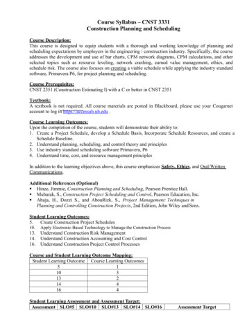
DECEMBER 2008 ICE STORMChapter IV - System Planning, Design, Construction, and ProtectionFigure IV-3 – Two 34.5kV sub-transmission lines located on the Unitil system. (Photo by NEI - Unitil System)Distribution SystemIn this report, the distribution system will be defined as that portion of the electric systemextending from the distribution substation to the end customer, including the customer’s meter.The portion of the electric system from the secondary (low voltage) side of the distributiontransformer to the customer meter is normally referred to as a “service” or “service drop.”Distribution poles in New Hampshire are typically jointly owned by the local electric utility andthe local telephone company to minimize the number of poles needed to provide both services.Distribution poles may also be used to support electric equipment, street lighting, cable TV lines,fiber optic lines, and municipal alarm and communication lines. A considerable amount ofelectric and communications material may be attached to a single pole.Figure IV-4 shows an urban distribution pole located in Concord, New Hampshire. Inspection ofthis installation reveals the following equipment has been attached to the pole: Cross-arm with three distribution, high voltage conductors on insulatorsSingle phase distribution transformer to convert the distribution high voltage to 120/240Volt residential service voltageNEI Electric Power EngineeringPage IV-5
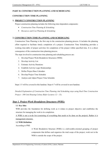
DECEMBER 2008 ICE STORMChapter IV - System Planning, Design, Construction, and Protection Street lightTwo, triplex service conductors to serve a residential customerMultiple, large bundle telephone nsCablingFigure IV-4 – Urban distribution line located in Concord, New Hampshire.(Photo by NEI – Unitil System)Figure IV-5 shows a typical rural overhead distribution line located in southwestern NewHampshire. Distribution lines in New Hampshire are usually constructed adjacent to roads andhighways where they share a combination of public and private land and compete for space withtrees. This distribution line follows the road and each pole must be capable of handling thecables and equipment shown in Figure IV-4. Unlike the transmission and sub-transmission linesshown in Figure IV-1, Figure IV-2, and Figure IV-3, the ROW under this line has not been wellcleared.NEI Electric Power EngineeringPage IV-6
DECEMBER 2008 ICE STORMChapter IV - System Planning, Design, Construction, and ProtectionFigure IV-5 -Typical PSNH distribution circuit near Greenville, New Hampshire.(Photo by NEI - PSNH System)Distribution systems are planned, designed, constructed, and protected in accordance with theNational Electrical Safety Code and good utility distribution practices. During the December2008 ice storm, the electric distribution system in New Hampshire was extensively damaged byice laden tree limbs and whole trees falling onto power lines. Absence of a clear ROW, as isshown in Figure IV-5, can contribute to such damage.Electric Distribution SubstationsElectric distribution substations are used to reduce voltage levels from transmission and subtransmission to distribution level. This allows power to be delivered by distribution lines todistribution transformers that further reduce the voltage to a level useable by the customer.Figure IV-6 shows a relatively small electric distribution substation that reduces Unitil’s 34.5 kVsub-transmission voltage to 13.8 kV, which is then distributed to industrial, commercial, andresidential customers.A typical electric distribution substation will have the following equipment: Incoming transmission or sub-transmission lineDistribution transformerTransformer protection including such things as fuses, circuit breakers and lightningarrestersVoltage regulators to raise or lower the distribution voltage as requiredNEI Electric Power EngineeringPage IV-7
DECEMBER 2008 ICE STORMChapter IV - System Planning, Design, Construction, and Protection Electric outgoing distribution circuits complete with metering and circuit protection ascircuit breakers or reclosersA substation fence for safety and security purposesFigure IV-6 – 34.5kV to 13.8kV Unitil electric distribution substation located inEast Kingston, New Hampshire. (Photo by NEI-Unitil System)During the December 2008 ice storm, the electric distribution substations were affected mainlyby external causes, with minimal internal problems. Electric distribution substations lost powerdue to tree limbs and trees falling onto incoming power lines. The resultant damage causedcircuit breakers and reclosers to open upstream from the substations to disconnect the damagedlines. In most cases, equipment located inside the electric distribution substations wasunaffected, except for the normal operation of circuit breakers due to problems occurring outsideof the substation.Transmission System ProtectionTransmission systems are typically constructed and protected as a network system4 such that afaulted (short circuited) section of the system can be isolated without causing interruption of4Network system – An electric system that has at least two sources (lines) of power supply such that the loss of oneline will not result in loss of power to an electric customer.NEI Electric Power EngineeringPage IV-8
DECEMBER 2008 ICE STORMChapter IV - System Planning, Design, Construction, and Protectionpower to a customer. Transmission system protection includes not just the protection of thetransmission lines, but also the generators, transformers, and substation buses that complete thetransmission system. However, for the purpose of this report, the focus on transmission systemprotection will be limited to the protection of the transmission lines. (See Appendix E for a morethorough and technical discussion of transmission system protection.)Distribution System ProtectionElectric distribution systems, including those in New Hampshire, are typically radial systems,which means that the lines originating at the substation radiate outward toward their loads. Theradial power lines normally have multiple taps from the main feeder, called laterals, whichprovide power to individual customers. The distribution system protection consists of feederbreakers with relay controls, feeder reclosers possibly both inside and outside of the substation,line sectionalizers, and line fuses. In the case of a large weather event, such as the December2008 ice storm, a majority of the distribution system may be affected. As a large storm eventdevelops, more and more of the distribution system, including main distribution lines, willexperience permanent faults. This results in the loss of the ability to effectively sectionalize adistribution line or restore power through automatic reclosing. During the early hours of theDecember 2008 ice storm, the distribution system protection performed as expected by removingpermanently faulted sections of line and restoring power through automatic reclosing fortemporary faults. As the damage from the storm increased, the distribution system protectioncontinued to perform as expected by disconnecting lines as they were damaged, causing moreand more customers to be without power. (See Appendix E for a more thorough and technicalexplanation on distribution system protection.)Substation ProtectionThe degree of substation protection is often determined by the size and importance of thesubstation itself as it relates to the power system. Normally, higher voltage substations andlarger transformer sizes require more intricate protection schemes, whereas smaller substationsmay only require minimal protection, such as fuses. (See Appendix E for a more thorough andtechnical discussion on substation protection.)NEI Electric Power EngineeringPage IV-9
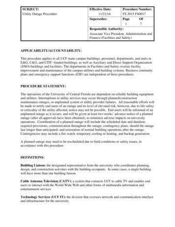
DECEMBER 2008 ICE STORMChapter IV - System Planning, Design, Construction, and ProtectionSCADASupervisory control and data acquisition (SCADA) systems are used to collect real-timeinformation about the power system and provide control of system equipment. SCADA providesa centralized master station with information from substations and equipment in the field. Theinformation collected can help in load management, provide important information on the healthof the power system, and help determine the location of damaged lines and equipment. SCADAsystems also make it possible for equipment in substations and in the field to be operatedremotely to provide voltage control, switching for maintenance and repair work, and rerouting ofpower around faulted sections of lines.Covered WireCovered wire (tree wire and covered wire systems (Hendrix Cable )) is commonly used in NewHampshire on overhead sub-transmission and distribution lines. Covered wire consists of bareconductors with a rubber or plastic outer layer. The purpose of the outer layer is to provideprotection from incidental contact with trees that could cause temporary faults (short circuits).Temporary faults which may occur on bare overhead conductors become a nuisance becauseprotective devices must operate by disconnecting the circuit to clear the fault. This may cause amomentary or prolonged power outage on that line due to what may be a relatively minorcontact. The rubber outer layer on covered wire systems may be effective in protecting the linefrom vegetation contact during everyday operations; it does not provide a substantial advantageduring large weather caused events. Over time it has not been found to provide a substantialadvantage over bare wire. Although covered wire may allow power to continue to be suppliedeven when contacted by trees and other objects, the power line must be de-energized to cleardebris and repair damage. In addition, when damaged, the covered wire may be more difficult torepair and replace.5 6 7Figure IV-7 is a photograph of a covered wire installation on the NHEC system which shows thecovered wire installation at the top of the pole and a standard cross arm distribution circuit oncross-arms below. The photo shows that the three covered wires are separated by a spacer andthe entire assembly is attached to the messenger wire at the top. Note the more compactconstruction and the lack of need for a standard cross-arm, which are both advantages of thecovered wired installation. The bare messenger wire is continuously grounded and acts as asystem neutral wire. Therefore, it does not need to be covered.5Demmer, K. Manager Electrical Distribution New Hampshire, National Grid. Interview by Ackerman, A. May 8,2009.6Doe, S. Manager-System Planning & Strategy, PSNH. Interview by Ackerman, A. June 2, 2009.7Zogopoulos, A.J. Design and Standards Specialist, Unitil. Interview by Nelson, J., May 21, 2009.NEI Electric Power EngineeringPage IV-10
DECEMBER 2008 ICE STORMChapter IV - System Planning, Design, Construction, and ProtectionMessengerWireSpacerFigure IV-7 – Covered wire system in Colebrook, New Hampshire. (Photo Courtesy NHEC)Pole Construction and LoadingPrevailing laws and practices in most states, including New Hampshire, require overhead linesbe designed, at the very minimum, to meet the National Electrical Safety Code (NESC).8 Inaddition, some states, such as California, have adopted by law their own codes, which are similarto NESC requirements.9 In the United States most structures, other than transmission lines, arebuilt according to the International Building Code (IBC), which often defaults to AmericanSociety of Civil Engineers (ASCE) standards on such issues as loading and design methods.Current practice is to design structures using two well accepted design methods. The first andoldest is the “Allowable Stress Design” (ASD) method, and the other is “Load and ResistanceFactor Design” (LRFD), which is the method most commonly taught in colleges and appears tobe the one toward which the industry is moving.8New Hampshire PUC 300 Rules, Part PUC 306.1.Dagher, H.J. (2001). “Reliability of Poles in NESC Grade C Construction.” IEEE Rural Electric PowerConference 2001, Pgs C4/1-C4/6. (10.1109/REPCON.2001.949521).9NEI Electric Power EngineeringPage IV-11
DECEMBER 2008 ICE STORMChapter IV - System Planning, Design, Construction, and ProtectionThe NESC, however, uses neither of these commonly accepted methods. Instead it historicallyused an ultimate stress design method with overload factors included to provide the neededfactors of safety. The NESC method differs from all other commonly accepted design methods,and loading requirements contained in the NESC are different than those used in any other code.NESC rules for selection of design loads and for safety factors are largely based on successfulexperience, but have little basis in theory.10 The more modern methods of design such as LRFDhave been developed using successful experience as well as structural theory that has becomeaccepted over the years. As a result, the NESC in recent editions has begun to gradually movetoward the methods commonly accepted for other types of construction. The NESC should beconsidered in process of transition, and its requirements do not closely match the requirementsthat would be necessary to build a habitable structure.The load and strength factors used in the 2007 version of the NESC are designed for use withboth traditional NESC district loading and 50 years recurrence loading as shown in ASCEStandard 7 maps (See Figures F-2 and F-3 in Appendix F). Even though only NESC districtloading cases are required for structures less than 60 feet, it is recommended that the higher windand ice loading cases required by ASCE data also be taken into account for the design of allstructures no matter their height. This approach should produce a more realistic design than theNESC district loading cases alone for the conditions that can be expected in New Hampshire.This would include determining from local sources the actual wind and ice loads that can beexpected in the special wind areas shown on ASCE maps, rather than relying on loading datafrom NESC maps (See Appendix F for a more thorough and technical discussion on poleconstruction and loading as well as ASCE Standard 7 maps).B. EVALUATIVE CRITERIAPrior to the December 2008 ice storm, each utility should have been planning, designing, anddeveloping electrical system protection schemes in order to maximize reliability of its systemduring an abnormal event. The following criteria were used to assess each utility:1. The transmission and sub-transmission system should be properly planned, designed,constructed, and protected.2. The distribution system should be properly planned, designed, constructed, and protected.3. Substations should be properly planned, designed, constructed, and protected.1.The transmission and sub-transmission system should be properly planned,designed, constructed, and protected.10Bingel, Nelson and Dagher, Habib, et.al. (2003). “Structural Reliability-Based Design of Utility Poles and theNational Electrical Safety Code.” Transmission and Distribution Conference and Exposition 2003, Vol. 3, Pgs1088-1093. (10.1109/TDC.2003.1335100).NEI Electric Power EngineeringPage IV-12
DECEMBER 2008 ICE STORMChapter IV - System Planning, Design, Construction, and Protection 2.The correct ice and wind loading conditions should have been used during design.The proper criteria should be used to determine when to replace and upgrade agingequipment.Aging equipment should not have had an adverse impact on the system during the storm.The utility should have adequate planning and engineering staff to perform all necessaryplanning, design, and protection work in a timely fashion.The system should be designed and constructed to handle expected extreme weatherconditions.The protection systems should be well designed, coordinated, and maintained.Reasonable planning, design, protection, and construction budgets should be available inorder to maintain and operate the existing system and to design and build new parts asneeded.The distribution system should be properly planned, designed, constructed, andprotected. 3.Distribution lines and equipment should be properly designed.The correct wind and ice loading criteria should be used in planning and design.The proper criteria should be used to determine when to replace and upgrade agingequipment.Aging equipment should not have had an adverse impact on the system during the storm.Proper planning for distribution line sectionalizing should exist.The utility should have adequate planning and engineering staff to perform all necessaryplanning, design, and protection work in a timely fashion.The protection systems should be well designed, coordinated, and maintained.Reasonable planning, design, protection, and construction budgets should be available inorder to maintain and operate the existing system and to design and build new parts asneeded.Substations should be properly planned, designed, constructed, and protected. Substations should be adequately planned and constructed to serve the loads undervarious system conditions.Substations should not have been adversely impacted during the storm.The proper criteria should be used to determine when to replace and upgrade agingequipment.Aging equipment should not have had an adverse impact on the system during the storm.The utility should have adequate planning and engineering staff to perform all necessaryplanning, design, and protection work in a timely fashion.Substations should be well designed and constructed to handle expected extreme weatherconditions.NEI Electric Power EngineeringPage IV-13
DECEMBER 2008 ICE STORMChapter IV - System Planning, Design, Construction, and Protection The protection systems should be well designed, coordinated, and maintained.Reasonable planning, design protection, and construction budgets should be available inorder to maintain and operate the existing system and to design and build new parts asneeded.The following tables indicate the extent to which each of the utilities met the above criteria.These tables were not prepared to compare one utility with another. The utilities are verydifferent, face different problems, and experienced different amounts of damage to theirsystems. These tables were prepared to show where each utility may improve itsperformance in preparation for the next storm or other disaster. A further explanation for theimprovements that are recommended to each of the utilities may be found in the findings andconclusions section of this report. The meanings of the symbols used in the tables are:Improvement is needed as stated in the reportAdequate with minor improvements suggested as stated in the reportEffective with no improvements noted.NEI Electric Power EngineeringPage IV-14
DECEMBER 2008 ICE STORMChapter IV - System Planning, Design, Construction, and ProtectionTable IV-1 – PSNH system planning, design, construction & protection evaluation matrix.1) THE TRANSMISSION AND SUB-TRANSMISSION SYSTEM SHOULD BE PROPERLY PLANNED, DESIGNED, AND PROTECTED.The correct ice and wind loading condition were used during design.The proper criteria were used to determine when to replace and upgrade aging equipment.Aging equipment did not have an adverse impact on the system during the storm.The utility had adequate planning and engineering staff to perform all necessary planning, design, and protection work in a timely fashion.The system was designed and constructed to handle expected extreme weather conditions.The protection systems were well designed, coordinated and maintained.Reasonable planning, design, protection, and construction budgets were available in order to maintain and operate the existing system and to design and build new parts as needed.2) THE DISTRIBUTION SYSTEM SHOULD BE PROPERLY PLANNED, DESIGNED, AND PROTECTED.Distribution lines and equipment were being properly designed.Proper wind and ice loading criteria were used in planning and design.Proper planning criteria were used to determine the need to replace and upgrade aging equipment.Aging equipment did not have had an adverse impact on the system during the storm.Proper planning for distribution line sectionalizing exists.Adequate planning and engineering staff is available to perform all necessary planning, design, and protection work in a timely fashion.The protection systems were well designed, coordinated, and maintained.Reasonable planning, design, protection, and construction budgets were available in order to maintain and operate the existing system and to design and build new parts as needed.3) SUBSTATIONS SHOULD BE PROPERLY PLANNED, DESIGNED, AND PROTECTED.Substations were adequately planned and constructed to serve the loads under various system conditions.Substations were not adversely impacted during the storm.Proper planning criteria were used to determine the need to replace and upgrade aging equipment.Aging equipment did not have an adverse impact on the system during the storm.Adequate planning and engineering staff were available to perform all necessary planning, design, and protection work in a timely fashion.Substations were well designed and constructed to handle expected extreme weather conditions.The protection systems were wel
Oct 30, 2009 · NEI Electric Power Engineering Page IV-8 Electric outgoing distribution circuits complete with metering and circuit protection as circuit breakers or reclosers A substation fence for safety and security purposes Figure IV-6 – 34.5kV to 13.8kV Unitil electric distribution