Transcription
SUPPLEMENTALMANUALFACTORY-INSTALLEDABB VARIABLE FREQUENCYDRIVES (VFD)IN RENEWAIRE(ERV) VENTILATORSMODEL SHOWN: ACS 320TABLE OF CONTENTSVFD KEYPADS IN E-BOXProduct info . 2Installation . 3-9Operation. 10-16RENEWAIRE.COM
ABB VARIABLE FREQUENCY DRIVESPRODUCT INFOABOUT ABB VFDSABB ACS320 VFDs are generally supplied in indoor ERVs and ABB ACS355 N831 VFDs in roof top ERVs.Both models have built in BACnet building communication protocol and the ACS355 N831 also haslow ambient firmware that extends the lower starting temperature limit to -25 F.FOR COMPLETE ERV INSTALLATION YOU WILL ALSO NEED: Standard Installation and Operation Manual for the ERV – physical installation and duct connection,maintenance procedures, etc. Supplemental Wiring Schematic Manual – complete unit wiring diagrams. User’s Manual ACS320 Drives or Users Manual ACS355 Drives – ABB’s user’s/installer’s manual.More detailed information is available online in the Document Library at www.abb.com/drives.PLANNINGYOUR INSTALLATIONWARNINGRISK OF FIRE, ELECTRIC SHOCK, OR INJURY. OBSERVE ALL CODES AND THE FOLLOWING:1. Before servicing or cleaning the unit, switchpower off at disconnect switch or service paneland lock-out/tag-out to prevent power frombeing switched on accidentally. More than onedisconnect switch may be required tode-energize the equipment for servicing.2. This installation manual shows the suggestedinstallation method. Additional measures maybe required by local codes and standards.3. Installation work and electrical wiring must bedone by qualified professional(s) in accordancewith all applicable codes, standards andlicensing requirements.4. Any structural alterations necessary forinstallation must comply with all applicablebuilding, health, and safety code requirements.5. This unit must be grounded.6. Use the unit only in the manner intended by themanufacturer. If you have questions, contactthe manufacturer.7. When cutting or drilling into unit, wall orceiling, do not damage electrical wiring andother hidden utilities.8. Do not re-wire the VFD(s) to control more thanone motor per VFD.9. Do not operate the motors in this unit abovethe motor’s rated full load amps (FLA) asindicated on the unit’s nameplate.NOTE: VFD(s) in this unit can be operated in many ways. This Manual provides only an outline of common methods.WARNINGDO NOT OPERATE VFD IN CONDITIONS OUTSIDE OF TEMPERATURE LIMITS. The manufacturer’s normalambient temperature limits for ACS320 VFDs are 14 F to 122 F. RenewAire has worked with the manufacturerto implement low-ambient-start firmware for the ACS355 N831 that extends the lower temperaturelimit for starting the VFD down to -25 F, which has been validated by manufacturer and RenewAire testing.The manufacturer recommends that the VFD not be operated for prolonged periods at temperatures below14 F to ensure longevity of the VFD. RenewAire commercial ERVs are VFD ready, in extreme climatesconsider field installing VFDs in a climate controlled indoor electrical cabinet.2RENEWAIRE.COM ABB VFD SUPPLEMENTAL MANUAL 1.800.627.4499
ABB VARIABLE FREQUENCY DRIVESINSTALLATION“ON” AND “SPEED” SIGNALSVFD operation in this unit is dependent on two signals: an ON signal and a SPEED (or REFERENCE) signal.The sources and types of these signals can vary. If the ERV is equipped with dampers the ON signal to theVFD comes from the end switch on the damper. If the ERV is not equipped with dampers, the ON signalcomes from an external control connected directly to the VFD. When an ON signal is received by the VFD,it starts the motor. The VFD then operates the blower at the speed established by the SPEED signal. TheSPEED signal is often provided by an external control, but in some applications “pre-set” speeds are setinside the VFD and are selected by external switches or relays.PRINCIPLES OF EXTERNAL CONTROLThis ERV can be operated by various externalcontrol devices including remote switch or relay,digital time clock with relay, occupancy sensorwith relay, and carbon dioxide sensor with relayand analog output. These devices are commonlyknown as 2-wire, 3-wire, and 4-wire devices.A Building Management System (BMS) can controlthis ERV through relay contacts and with 0-10vdcor 4-20mA analog inputs.The external control devices can be connected tothis ERV to operate each blower independently orPLANNING YOURINSTALLATIONfor one blower to act as leader and the otherblower to act as follower. In leader-followermode, a single external switch or relay calls foroperation and the leader VFD sets SPEED to internalpresets, or in response to an analog input signal.The follower VFD then operates at either exactlythe same speed, at an offset above or below theleader’s speed, or at a scaled speed.The VFD’s are pre-programmed at the factory soonly a few parameters need change for aspecific installation.CONNECTING EXTERNAL CONTROLSIf this ERV is equipped with damper(s), the ON signal is connected to the terminal strip in the electricalenclosure (“E-box”). If this ERV is not equipped with damper(s), and has 2 VFDs, the ON signal isconnected directly to the VFDs. The SPEED signals are always connected directly to the VFD(s).WIRE ROUTINGRoute input power cables, motor cables and controlcables separately to decrease electromagneticinterference caused by the rapid changes inthe drive output voltage. Where control cablesmust cross power cables make sure that theyare arranged at an angle as near to 90 degreesas possible. See the ABB VFD manual for moredetailed wire routing instructions.Power cables and control cables can be broughtinto the bottom of the electrical box attached to theERV unit or through the bottom of the unit itself.There are plugged holes to run control wires andpower wires between the electrical box and theunit interior, marked on the interior of the ERV unitand another plugged hole in the unit compartmentdivider to run wires to VFDs in the other airstreamcompartment if needed.In some configurations the VFD and/or VFDprotective guard may need to be removed toaccess the control wire hole plug to run wires.A label is located in the ERV on the left interiorwall indicating the power and control wire holeplug locations. Bring wires out from the top orbottom of the VFD mounting bracket and notthrough the mounting bracket window whenrouting wires if the VFD is mounted over thehole plug.After the wires are run, apply caulk around thewires at wire bushings used between the electricalbox and ERV unit and between compartmentsin the unit to prevent air leakage between thesecompartments.1.800.627.4499 ABB VFD SUPPLEMENTAL MANUAL RENEWAIRE.COM3
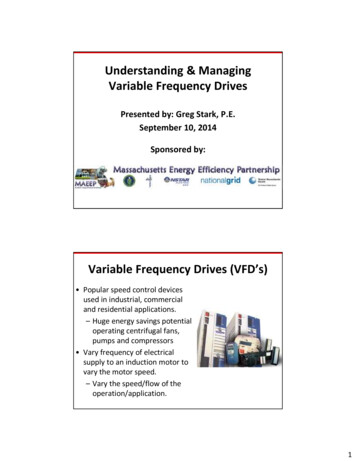
ABB VARIABLE FREQUENCY DRIVESINSTALLATIONPLANNING YOURINSTALLATIONPURPOSE OF PROVIDED KEYPADEach VFD has a keypad which is accessible at theE-box while the unit is operating.You can check the status of the VFD at the keypad,and make changes to the VFD parameters at thekeypad. You can manually control the VFD from thekeypad during start-up and commissioning.VFD is factory programmed to cover most needsbut some parameters will need to be set to interactwith the external control system.Access the keypad(s) through the removable coverto the E-box.ABB KEY PAD BUTTONSThe function of eachSoftkey changesand is shown justabove the Softkey inthe display.Up/Down ButtonsSoftkeySoftkey“Auto”“OFF”TECHNICAL SUPPORTHelp Key“Hand”For questions about applications not covered in this manual, and for questions specific to theABB Drives, contact ABB Technical Support at 800-HELP-365 (800-435-7365).A listing of ABB support and service contacts can be found on the Internet at www.abb.com/drives andselecting Sales, Support and Service Network.ABB manuals are available as PDFs at www.abb.com/drives; select Document Library.Related ABB Manuals:ACS320 User’s Manual 3AUA0000062599ACS320 Short Form User’s Manual 3AUA0000086933ACS355 User’s Manual 3AUA0000066143ACS355 HVAC with BACnet ( N831) Supplement 3AXD50000024172FMBA-01 Modbus Adapter Module User’s Manual 3AFE68586704F-Series Fieldbus Adapter Modules Installation Note 3AXD50000008201ACS355 HVAC With BACnet ( N831) Document Guide 3AXD50000023355ABB offers training courses on their VFDs; navigate to www.abb.com/drives and select Training Courses.For questions about applications covered in this manual, and for questions about how the VFDs areinstalled in your RenewAire ERV unit, contact RenewAire Customer Support at 800-627-4499.4RENEWAIRE.COM ABB VFD SUPPLEMENTAL MANUAL 1.800.627.4499
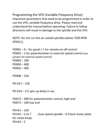
ABB VARIABLE FREQUENCY DRIVESINSTALLATION“ON” SIGNAL CONNECTIONSIf the ERV is equipped with Damper(s) and/or with just one VFD, the ON Signal control wires are connectedto the low-voltage terminal strip in the ERV E-box. See Fig. 1.WIRING OPTIONSInstall a jumper between terminals 2 and 3 to use the ERV’s on-board 24VAC power. Do this when theexternal control(s) have isolated contacts that don’t provide any voltage, as in the top two examples.Make no connections between terminals 1 & 2 and terminals 3-5 if the external control has a voltageoutput to provide the ON signal. This voltage must be 24VAC.With ERVs equipped with no dampers and 2 VFDs, the ON signal control wires are connected directly to theVFD. See Fig. 2 & 3.“SPEED” SIGNAL CONNECTIONSAny SPEED Signal connections are made directly to the VFD (see Figures 4,6 & 7). The VFDs can accept4-20mA or 0-10vdc analog control signals to operate at varying speeds. The VFDs also can acceptmomentary-contact inputs to operate at up to three pre-set speeds. VFD Parameters must be properly setto accept and act on Speed signals. Wiring for analog control signals should be twisted-pair, single- ordouble-shielded cable, with shield (and drain if provided) grounded at only one end of the cable.CAUTIONCapacitors in VFDsRetain ChargeAllow 2 minutes after shuttingoff power to the VFDs to allowthe capacitors in the VFD tofully discharge. Do not connector disconnect wires at the VFDwithout waiting 2 minutes.LEADER-FOLLOWER CONNECTIONSON and SPEED signals can be passed from the LEADER VFD to a FOLLOWER VFD. See Figures 3 & 5.WIRING SCHEMATICSF1CONNECTION OF ON SIGNALS TO LOW-VOLTAGE TERMINAL STRIP IN ERV E-BOX.1.800.627.4499 ABB VFD SUPPLEMENTAL MANUAL RENEWAIRE.COM5
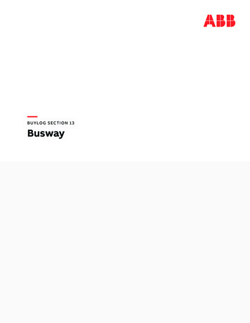
ABB VARIABLE FREQUENCY DRIVESINSTALLATIONSee Fig. 1 for Relay or Damper ActuatorConnection alternatives.SCR2AI13AGND410V5AI26AGND7A018AGND9DO NOT CONNECT POWER TOTERMINALS 9-15 ON EITHER 215ALTERNATIVE CONTROL WIRING: ON SIGNAL CONNECTED DIRECTLYTO ONE VFD, PASSED TO SECOND VFD FROM TERMINALS 17 & 19.Close contact toturn FA Blower ONSettingSCR2AI13AGND410V5AI26AGND7A019PARAMETER SETTINGS - FA VFDParameter18DO NOT CONNECT POWER TOTERMINALS 9-15 ON EITHER VFDParameter DescriptionAGND1014012 RUNRENEWAIRE.COM ABB VFD SUPPLEMENTAL MANUAL 1.800.627.4499Closes contact between 17 & 19 whenVFD is called to RUN.9111SCR2AI13AGND410V5AI26AGND7A01861112VFD (EA)NOTE: ERV may optionally haveonly one VFD.1VFD (FA)FACTORY CONTROL WIRING: ON SIGNALS CONNECTED TO EACH VFD.VFD (FA)F21215AGND10111719Install thesewires FA VFD will turnEA Blower ONVFD (EA)WIRING SCHEMATICS1215
ABB VARIABLE FREQUENCY DRIVESINSTALLATIONANALOG INPUTS TO PROVIDE THE SPEED SIGNALAnalog inputs are connected as shown below. It may be necessary to scale the response of the VFD to theanalog SPEED signal. See example of VFD Parameter Scaling in Figure 9 (F9). 6&5 , *1' 9 , *1' YGF &21752//(5 N2 0 327(17,20(7(5 *1' &RQQHFWLRQV IRU YGF &RQWUROOHU 6HW -XPSHU RU VZLWFK , WR %27720 RU 2)) SRVLWLRQ , , 9)' XVLQJ YGFEXAMPLES OF ANALOG INPUT CONNECTIONS. 6LJQDO FDEOH VKLHOG VFUHHQNOTE: All wiring for analog signals connected to theVFDs should be double - or single-shielded twisted-paircable. Ground the shield at one end of the cable only.)UHTXHQF\ ,QSXW YGF)UHTXHQF\ ,QSXW &RPPRQ JURXQG5HIHUHQFH 9ROWDJH3 5 0(7(5 6(77,1*6 *(1(5 / 6HWWLQJ3DUDPHWHU5HOD\ &RQWDFW RU FWXDWRU (QG 6ZLWFK)DFWRU\ :LUHG P &21752//(5 6&5 , *1' 9 , *1' *1' &RQQHFWLRQV IRU P &RQWUROOHU 6HW -XPSHU RU VZLWFK , WR 723 RU 21 SRVLWLRQ , , 9)' XVLQJ P F4 WIRING SCHEMATICS6LJQDO FDEOH VKLHOG VFUHHQ , 3DUDPHWHU 'HVFULSWLRQ(QDEOHV )UHTXHQF\ WR EH FRQWUROOHG E\ DQDORJ LQSXW VLJQDO IURP H[WHUQDO FRQWURO 3 5 0(7(5 6(77,1*6 YGF 1 /2* ,13873URSHUO\ VFDOHV GLVSOD\ RI LQSXW )UHTXHQF\ ,QSXW P )UHTXHQF\ ,QSXW &RPPRQ JURXQG 96HWV GLVSOD\ XQLWV DV 9ROWV 93URSHUO\ VFDOHV GLVSOD\ RI LQSXW 93URSHUO\ VFDOHV GLVSOD\ RI LQSXW 5HOD\ &RQWDFW RU FWXDWRU (QG 6ZLWFK)DFWRU\ :LUHG3 5 0(7(5 6(77,1*6 P 1 /2* ,13873URSHUO\ VFDOHV GLVSOD\ RI LQSXW P 6HWV GLVSOD\ XQLWV DV P PSV P 3URSHUO\ VFDOHV GLVSOD\ RI LQSXW P 3URSHUO\ VFDOHV GLVSOD\ RI LQSXW WIRING TWO VFDS FOR LEADER-FOLLOWER OPERATIONOne VFD can provide the SPEED signal to a second VFD, as shown below.63((' LQSXW ZLULQJ QRW LOOXVWUDWHG 6&5 , *1' 9 , *1' *1'Connect VFDs as shown FA VFD will pass the Frequency(Speed) Signal to the EA VFD.Use shielded cable and groundthe shield to Terminal 1 oneither VFD6LQFH WKH LQSXW IURP WKH 8SSHU 9)' LV P LQSXW SODFH -XPSHU RU VZLWFK , DW 723 RU 21 SRVLWLRQ , , 6&5 , *1' 9 , *1' *1' 9)' XVLQJ YGFLEADER-FOLLOWER CONNECTION. NOTE: Parameters 1501 and 1502 can be used toscale the Analog Output of the Leader VFD in order tooffset or correct the speed of the Follower VFD.)UHTXHQF\ 2XWSXW DOZD\V P )UHTXHQF\ 2XWSXW &RPPRQ JURXQG 9)' XVLQJ P F5 6LJQDO FDEOH VKLHOG VFUHHQIf the FA VFD is controlled by an analog input signal,it is likely that the FA VFD’s response to the analoginput will need to be scaled, using parameters 1104,1105, 1301 and 1302. See example of VFD ParameterScaling in Figure 9 (F9).If both VFDs are to run at the same speed, no scalingparameters need be applied to the EA VFD since it iscontrolled as a “Follower”.
ABB ACS320 VFDs are generally supplied in indoor ERVs and ABB ACS355 N831 VFDs in roof top ERVs. . See the ABB VFD manual for more detailed wire routing instructions. Power cables and control cables can be brought into the bottom of the electrical box attached to the ERV unit or through the bottom of the unit itself. There are plugged holes to run control wires and power wires between the .