Transcription
ERn Rack Mount EnclosureInstallation ManualRevision BC o p y r i g h t E le c tr o n i c T h e a t r e C o n t r o l s , I n c .All Rights reserved.P r o d u c t in f o r m a t i on a n d s p e c i f i c a t i o n s s u bj e c t t o c h a n g e .P a r t N u m b e r : 7180M2110 R e v BR e le a s ed : 2 0 1 2 - 0 8
ET C , U n i s o n , E D M X a r e e it h e r r e g i s t e r e d t ra d e m a r k s o r t r a d e m a r k s o f E l e c t r o n i c T h e a t r e C o n t r o l s , I n c . int h e U n i te d S t a te s a n d o t h e r c o u n t r ie s .E c h e l o n , LO N , L ONW ORKS a r e r e g i s t e r e d tr a d e m a r k s o f E c h e l on C or p o r a ti o n i n t h e U n i t ed S t a t es a n dother countries.A l l o t h e r t r a d em a r k s , b o t h m a r k e d a n d n o t m a r k e d , a r e th e p r o p e r t y o f t h e i r r e s p e c t i v e o w n e r s .E T C i n t e n d s t h i s d o c u m e n t , w h e t h e r p r i n t ed o r e l e c tr o n i c , to b e p r o v id e d i n i t s e n ti r e t y .
Table of ContentsIntroduction . . . . . . . . . . . . . . . . . . . . . . . . . . 1ERn Modules and Options. . . . . . . . . . . . . . . . . . . . . . . . . . . . . .2Warnings and Notice Conventions . . . . . . . . . . . . . . . . . . . . . . .4Contacting ETC . . . . . . . . . . . . . . . . . . . . . . . . . . . . . . . . . . . . . .4Prepare for Installation . . . . . . . . . . . . . . . . . 5Preparations . . . . . . . . . . . . . . . . . . . . . . . . . . . . . . . . . . . . . . . . . . . .6Unpack and Inspect . . . . . . . . . . . . . . . . . . . . . . . . . . . . . . . . . . .6Main Circuit Breaker Protection . . . . . . . . . . . . . . . . . . . . . . . . . .6Lockout/Tagout . . . . . . . . . . . . . . . . . . . . . . . . . . . . . . . . . . . .6General Lockout/Tagout Procedures: . . . . . . . . . . . . . . . . . . . .6Maximum Current Input . . . . . . . . . . . . . . . . . . . . . . . . . . . . . . . .7Rack Mounting Specifications . . . . . . . . . . . . . . . . . . . . . . . . . . . . . .8Dimensions and Weights . . . . . . . . . . . . . . . . . . . . . . . . . . . . . . .8Installation Environment Requirements . . . . . . . . . . . . . . . . . . . .8Wire Requirements. . . . . . . . . . . . . . . . . . . . . . . . . . . . . . . . . . . . . . .9Wire Routing and Specification . . . . . . . . . . . . . . . . . . . . . . . . . .9Control Specifications . . . . . . . . . . . . . . . . . . . . . . . . . . . . . . . . .9Data Types and Topologies . . . . . . . . . . . . . . . . . . . . . . . . .10DMX (Digital Multiplex) . . . . . . . . . . . . . . . . . . . . . . . . . . . . . .10Auxiliary 24 Vdc . . . . . . . . . . . . . . . . . . . . . . . . . . . . . . . . . . .10Install Enclosure . . . . . . . . . . . . . . . . . . . . . 11Install in a 19” Equipment Rack . . . . . . . . . . . . . . . . . . . . . . . . . . . .12Connect Wiring . . . . . . . . . . . . . . . . . . . . . . 13IEC Power Input Connector . . . . . . . . . . . . . . . . . . . . . . . . . . . . . . .14ERn Rack Mount Enclosure Power Input . . . . . . . . . . . . . . .14Connect Control Wiring . . . . . . . . . . . . . . . . . . . . . . . . . . . . . . . . . .15Connect Rear Panel I/O Data Terminations . . . . . . . . . . . . . . .15Terminate DMX Control Wiring . . . . . . . . . . . . . . . . . . . . . . .15DMX Input Termination: Screw Terminals Connector. . . . . . .15DMX Input/Output Termination: Insulation Displacement Connectors . . . . . . . . . . . . . . . . . . . . . . . . . . . . . . . . . . . . . . . . . .16Terminate LinkPower (LON ) Control Wiring . . . . . . . . . . . .16Terminate Auxiliary Power . . . . . . . . . . . . . . . . . . . . . . . . . .17Status Indicators . . . . . . . . . . . . . . . . . . . . . . . . . . . . . . . . . . .18Connect to Serial RS-232 . . . . . . . . . . . . . . . . . . . . . . . . . . .18Connect to Ethernet RJ-45 . . . . . . . . . . . . . . . . . . . . . . . . . .18Connect to Contact Inputs and Contact Outputs . . . . . . . . .19Terminate Contact Inputs . . . . . . . . . . . . . . . . . . . . . . . . . . . .19Terminate Contact Outputs . . . . . . . . . . . . . . . . . . . . . . . . . . .19Right I/O Board Terminations . . . . . . . . . . . . . . . . . . . . . . . . . .20Terminate DMX. . . . . . . . . . . . . . . . . . . . . . . . . . . . . . . . . . .20Table of Contentsi
Install Rack Options . . . . . . . . . . . . . . . . . . 21Rack Options . . . . . . . . . . . . . . . . . . . . . . . . . . . . . . . . . . . . . . . . . .22Install the Ride Thru Option (URTO) Kit . . . . . . . . . . . . . . . . . .22Connect Ride Thru Option Wiring . . . . . . . . . . . . . . . . . . . . .23Install a Paradigm Repeater or Dual Repeater Module . . . . . . .24Terminate LinkPower (LON ) Control Wiring . . . . . . . . . . . .25Terminate Auxiliary Power . . . . . . . . . . . . . . . . . . . . . . . . . .26Status Indicators . . . . . . . . . . . . . . . . . . . . . . . . . . . . . . . . . .27Install Redundant Power Supply . . . . . . . . . . . . . . . . . . . . . . . .28Status Indicator . . . . . . . . . . . . . . . . . . . . . . . . . . . . . . . . . . .28Final Installation and Power Up . . . . . . . . . 29Completing the Installation . . . . . . . . . . . . . . . . . . . . . . . . . . . . . . . .30Check Main Power Wiring . . . . . . . . . . . . . . . . . . . . . . . . . . . . .30Putting the Rack Back Together . . . . . . . . . . . . . . . . . . . . . . . .30Aux Power and LinkPower Status Indicators. . . . . . . . . . . . . . .30Final Installation. . . . . . . . . . . . . . . . . . . . . . . . . . . . . . . . . . . . .31iiUnison ERn Rack Mount Enclosure Installation Manual
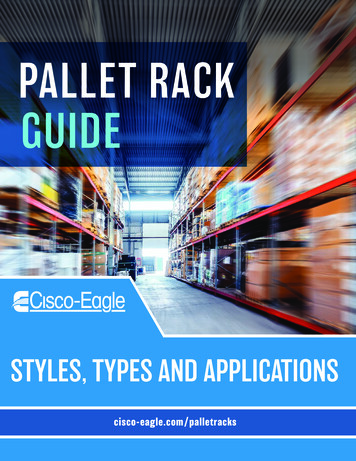
IntroductionWelcome to the installation manual for the Unison ERn rack mount external processingenclosure. This manual contains the procedures for safe and efficient installation of ERnseries processing racks, including wire termination and option kit installation.The ERn enclosure is available in two sizes, ERn2 and ERn4, which can be supplied forsurface mounting on a wall (reference the Unison ERn Wall Mount Enclosure InstallationManual) or with rack mounting brackets for installation in a standard 19” equipment rack.The ERn is available in three voltage options, 120, 230, and 240 VAC to meet yourinstallation requirements.The ERn provides Unison architectural control to distributed Unison, Sensor3, or otherDMX512 dimming systems. Used stand alone or in multi-processor network systems, theERn series enclosure offers elegant low-profile rack mounting, integrated back-lit controlelectronics, and the ultimate in architectural lighting control versatility.ERn4-RMERn2-RMThe ERn2 enclosure provides two module slots, one slot for the Paradigm architecturalcontrol processor (P-ACP) and one for use of the Paradigm station power module (P-SPM)or a blank (air flow) module (ERn-BM). The accessory tray in the bottom of the enclosurecan be used for either an optional redundant rack power supply (ERn-RPS) or blank optionmodule.Rack MountThe ERn4 enclosure provides four module slots, two slots which can be used for Paradigmarchitectural control processor’s (P-ACP) and an additional two slots for use of optionmodules such as the Paradigm station power module (P-SPM) or a Paradigm repeatermodule (P-REP). Alternatively, the top two slots in the enclosure may be used for a dualparadigm repeater module (P-DREP).The accessory tray in the bottom of the enclosurecan be used for either an optional redundant rack power supply (ERn-RPS) or the blankoption module.ModelVoltage / FrequencyNotesERn2-RM-120ERn2-RM-230CE85-120 VAC, 47-63 Hz (single phase)180-265 VAC, 47-63Hz (single phase)ERn2-RM-240180-265 VAC, 47-63 Hz (single phase)ERn4-RM-120ERn4-RM-230CE85-120 VAC, 47-63 Hz (single phase)180-265 VAC, 47-63Hz (single phase)ERn4-RM-240180-265 VAC, 47-63 Hz (single phase)External processing rack configured for 19”rack mounting utilizing 5 rack units (or 5U) ofrack space. Use with one Paradigmarchitectural control processor (ACP) and oneoption module.External processing rack configured for 19”rack mounting utilizing 9 rack units (or 9U) ofrack space. Use with up to two Paradigmarchitectural control processors (ACP) and upto two option modules.Introduction1
ERn Modules and PartNumberP ural ControlProcessor7182A1001Paradigm StationPower ModuleThe Paradigm ACP provides powerful and flexible control forarchitectural and theatrical applications with straightforwardintegrated networking for both NetConnect and LinkConnectnetworks. Tool-free installation into the ERn enclosure. Up to twoParadigm ACPs may be installed in the ERn4 enclosure. Features an easy to navigate user interface which is usablewith the door attached. Supports up to 62 Unison control stations over the LonWorksnetwork with the use of Paradigm station power and repeatermodules. Provides two ports of one DMX universe each (512 addresseseach), individually switchable between input and output.The Paradigm SPM provides power for Unison control stationsover the LinkPower network and provides the station data buslength up to 1,640 feet (500m). Tool-free installation into an ERn enclosure. Supplies LinkPower for up to 32 Unison control 0042Paradigm StationRepeater ModuleThe Paradigm REP module extends the system station bus length1,640 feet (500m) and increases the possible station count by anadditional 30 stations. For use only in an ERn4 enclosure. Tool-free installation into an ERn4 enclosure. For use in an ERn4 enclosure only.Airflow Option Module The ERn BM is used to fill empty module space in the ERn seriesenclosure, maintaining the convection cooled design. Tool-free installation into an ERn enclosure.Paradigm Dual Station The Paradigm DREP module extends the system station busRepeater Modulelength 3,280 feet (1,000m) through two separate topology-freeEchelon segments, each supporting 1,640 feet (500m). Tool-free installation into and ERn4 enclosure. The dual repeater module also adds support for up to 30additional Unison architectural control stations. For use in an ERn4 enclosure only.Unison ERn Rack Mount Enclosure Installation Manual
URTO7180A1410ERn-RPS 7180A1401Note:IntroductionUnison Ride ThruOption KitERn RedundantPower SupplyThe URTO kit provides power for one Paradigm architecturalcontrol processor in the host enclosure for a limited time (minimumof 12 seconds) during brief power outages or drop outs. If installed in an ERn4 enclosure, one URTO is required perParadigm ACP.The ERn RPS provides an additional rack power supply thatpowers the ERn enclosure if the primary rack power supply fails.The redundant power supply (ERn-RPS) is not supported in ERn4 enclosures at230 VAC. Instead the ERn4 at 230 VAC is shipped from the factory with a rackpower supply installed in the top (normal) position and in the lower option moduleslot as standard.3
Warnings and Notice ConventionsThese symbols are used in ETC documentation to alert you to danger or importantinformation:Note:Notes are helpful hints and information that is supplemental to the main text.CAUTION:A Caution statement indicates situations where there may be undefined orunwanted consequences of an action, potential for data loss or an equipmentproblem.WARNING:A Warning statement indicates situations where damage may occur, peoplemay be harmed, or there are serious or dangerous consequences of anaction.WARNING:RISK OF ELECTRIC SHOCK! This warning statement indicates situationswhere there is a risk of death by electric shock.Contacting ETCFor questions about Unison rack system delivery, contact ETC Systems Group. For generalinformation, your most convenient resources are the references provided in this manual. Tosearch more widely try the ETC web site at www.etcconnect.com.For technical questions about Unison rack systems, contact ETC Technical Servicesdirectly at one of the offices listed below. Emergency service is available from all ETCoffices outside of normal business hours. When calling for assistance, please have thefollowing information handy: Your location and job name. A complete list of ETC equipment. A complete list of other installed products and components connected to the systemyou are troubleshooting. DMX control source, if any.AmericasUnited KingdomETC InternationalTechnical Services Department3031 Pleasant View RoadMiddleton, WI 53562800-775-4382 (USA, toll-free) 1-608 831-4116service@etcconnect.comElectronic Theatre Controls, Ltd.Technical Services Department26 - 28 Victoria Industrial EstateVictoria Road,London W3 6UU, UK 44 (0)20 8896 1000service@etceurope.comAsiaGer manyETC Asia, Ltd.Technical Services DepartmentRoom 1801, 18/F, Tower 1, Phase 1Enterprise Square9 Sheung Yuet RoadKowloon Bay, Kowloon, Hong Kong 852 2799 1220service@etcasia.comElectronic Theatre Controls, GmbHTechnical Services DepartmentOhmstrasse 393607, Holzkirchen, Germany 49 (80 24) 47 00-0techserv-hoki@etcconnect.comPlease email comments about this manual to: TechComm@etcconnect.com4Unison ERn Rack Mount Enclosure Installation Manual
Chapter 1Prepare for InstallationThis chapter contains the following sections:1 Preparations . . . . . . . . . . . . . . . . . . . . . . . . . . . . . . . . . . . . . . . .6 Rack Mounting Specifications . . . . . . . . . . . . . . . . . . . . . . . . .8 Wire Requirements . . . . . . . . . . . . . . . . . . . . . . . . . . . . . . . . . .9Prepare for Installation5
Preparati onsUnpack and InspectBefore you begin installation, check your shipment and confirm it arrived complete andundamaged.Step 1:Check the shipping container for physical damage.Step 2:If you find damage, document it to help with a claim against your shipper.Step 3:Unpack your order and check the contents against the packing list to be sureyour order is complete.Step 4:If you discover a problem, call the ETC Systems Group at the closest office ofpurchase. See “Contacting ETC” on page 4.Main Circuit Breaker ProtectionBefore you begin installing the Unison ERn enclosure, make sure you have installed amain circuit breaker cabinet or other readily accessible input power disconnect device inthe same room or in close proximity of the installed ERn enclosure.WARNING:Enclosures installed without an accessible power disconnect device cannotbe serviced or operated safely. Follow all local codes and restrictions.When the disconnect device is not located near the installed enclosure, thedisconnect must allow for proper lockout / tagout.Lockout/TagoutEquipment should be locked out while being repaired. Accidents which occur becausemachinery that is being repaired and not locked out often result in serious injuries likeamputations, fractures, and even death. Locking out and tagging power at its source isimportant while repairing or adjusting equipment because it ensures that power does notreach the equipment being serviced. To lockout means to place a lock on a device that prevents the release of energy.Locking out is intended to prevent the unexpected startup or energizing of machineryand equipment during service and maintenance operations. To tagout means to place a tag on a switch or other shut off device which warns othersnot to start the piece of equipment. Tagout should only be used with lockout, unlesslocking out the equipment is impossible.General Lockout/Tagout Procedures:6 Notify all affected employees that a lockout/tagout procedure is ready to begin. Turn off the equipment at the control panel. Turn off or pull the main disconnect. Be sure all stored energy is released or restrained. Check all locks and tags for defects. Attach your safety lock or tag on the energy isolating device. Try to restart the equipment at the control panel to ensure that it is secured. Check the machine for possible residual pressures, particularly for hydraulic systems. Complete the repair or servicing work. Remove the safety lock and adapter.Unison ERn Rack Mount Enclosure Installation Manual
Let others know that the equipment is back in service.Maximum Current InputThe ERn enclosure draws a maximum current of 3 amps when fully populated.1Prepare for Installation7
Rack Mounting SpecificationsAn ERn configured for installation in a 19” equipment rack requires 5U of rack space for anERn2 and 9U of rack space for an ERn4. ERn enclosures are provided with rack mountingbrackets attached to the ERn enclosure at shipment. The locking door attaches to theequipment rack for a secure installation.Dimensions and Rn2-RM w/rack door8.8223194839.624416.67.7209.1ERn4-RM w/rack door14.1358194839.624423.8112511.3Installation Environment Requirements For your safety, you should install a circuit breaker cabinet or other readily accessibleinput power disconnect device in the same area as the Unison ERn enclosure.Breakers not in the same room must have a physical means to be locked off. A clean (not dusty), temperature controlled environment with the following conditions:CAUTION:8 ambient temperature of 32-104 F / 0-40 C ambient humidity of 10-90%, non-condensingHVAC systems must at all times maintain the specified ambient temperature at theUnison ERn enclosure. Restricted public access to prevent tampering. All CE equipment is tested to EMC category B environment.Unison ERn Rack Mount Enclosure Installation Manual
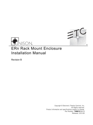
Wire RequirementsWire Routing and SpecificationThe rear panel of the Unison ERn rack mount unit includes a full compliment of removableinput and output connectors for easy installation. Additionally, an IEC power connector isprovided on the rear panel for input power.AUXDMX ADMXPASS-THRUNO4 COM4NO3COM3NO2COM2NO1DMX B COM1CONTACTOUTIN4GNDIN3GNDIN2GNDIN1GNDEthernet RS-232serial B B- COM1A1B1A1B1A1B2A2B2A2B2A2BA A- COM -B B- COM A A- COMAC INPUTCONTACTINAUXDMX ADMXPASS-THRUNO4 COM4NO3COM3NO2COM2NO1DMX BCOM1CONTACTOUTIN4GNDIN3GNDIN2GNDIN1GNDEthernet RS-232serial B B- COM1A1B1A1B1A1B2A2B2A2B2A2BA A- COM -B B- COM A A- COMLONCONTACTINLONControl SpecificationsThe riser below is typical of a system utilizing the ERn with the Paradigm architecturalcontrol processor (P-ACP) for control. Paradigm systems provide up to two DMX inputs forcontrol of more advanced systems. A Paradigm system also utilizes Net3 networking forsystem wide control.L IG HT I NGC O N T RO LSY S T EML IG HT I NGC O N T RO LUnisonSY S T EMPreset 1Preset 2SequencePreset 4Preset 9Preset 5Preset 10Preset 4Preset 5Unison HeritageStationsPreset 1Preset 1SequencePreset 5LinkPowerPreset 7Preset 2Preset 3Preset 3Preset 4Preset 6Preset 1Preset 2Preset 2Unison ERn4processing rackPreset 8Preset 3Macro RecordPreset 5Unison DRd12rack enclosurePreset 7Preset 2Preset 3Preset 3LinkPowerSENSOR3dimmer rackPreset 6Preset 1Preset 1Preset 2Preset 4SENSOR3dimmer rackPreset 8Preset 3Macro RecordPreset 4Preset 9Preset 5Preset 10Preset 4Preset 5Unison ParadigmTouchscreen LCDAux Power 24 VdcEos ConsolepowerfeedpowerfeedDMX inputto ERn rackETC Console(for optional stage lighting)powerfeed1Prepare for Installationpowerfeed9
The following table lists the recommended control wire types used in a typical Unison ERninstallation and the maximum wire runs allowed.EthernetLink Power DMX (Belden(Cat5 /Belden(Belden 8471)9729)1583a)PurposeTotal length of control wire(without repeater module)Maximum wire length (ERnto station)Maximum repeater 2810013134001600487N/AN/A1640500N/AN/AN/AN/AData Types and TopologiesLinkConnect with LinkPowerLinkConnect is the station communication bus from the architectural control processor tothe stations. LinkConnect is based on Echelon LonWorks with LinkPower bidirectionalprotocol, and uses one pair of wires (data , data - ). You should pull an additional 14 AWG(2.5mm2) wire for grounding when not installed in grounded metal conduit.ETC uses two types of LinkConnect networks, for SmartLink and Paradigm systems. Whilethe wiring for LinkConnect in SmartLink and Paradigm systems are the same, the twocommunication and control types are not interchangeable. SmartLink products arecompatible only with the SmartLink ACP, SmartLink station power module, and SmartLinkarchitectural control stations. Paradigm products are compatible only with the ParadigmACP, Paradigm station power modules, Unison Heritage architectural control stations, andParadigm touchscreens.Throughout this manual LinkConnect is referred to by the protocol it uses, LinkPower.LinkPower is topology-free and polarity independent, you can install your LinkPower dataruns in any desired combination of bus, loop, star, and home run. ETC recommends theuse of Belden 8471 (or approved equal) wire. The total combined length of a LinkPowerwire run cannot exceed 1,640 feet (500m) with a maximum distance of 1,312 feet (400m)between any two devices.Note:Repeater modules may be used to extend the Unison LinkPower station data busan additional 1,640 feet (500m) total wire, with a maximum distance of 1,313 feet(400m) between the repeater and any station.DMX (Digital Multiplex)DMX can address up to 512 channels of control. DMX is installed in a daisy chain topologyand includes one pair of wires (data and data-) plus an ISO ground. ETC recommends theuse of Belden 9729 (or approved equal) wire with a single end of line termination (90-150 For best DMX performance, twist the wires together as close to the pluggable connector aspossible.Auxiliary 24 VdcAuxiliary power is required when you are installing powered Unison control stations. ETCrecommends using two 16 AWG (1.5mm2) stranded wires for 24 Vdc auxiliary power to thecontrol station(s). Auxiliary power is topology-free. Maximum auxiliary voltage runs aredependant by the wire gauge and the distribution of auxiliary load determined byinstallation. The auxiliary supply is capable is of 36W (1.5A at 24Vdc).Note:10Terminate LinkPower station wiring and the auxiliary power wiring to the rearpanel of the ERn that will host the Paradigm station power module (P-SPM).Unison ERn Rack Mount Enclosure Installation Manual
Chapter 2Install EnclosureThis chapter contains instructions for installation of the ERn enclosure.The introduction contains the following sections: 2Install EnclosureInstall in a 19” Equipment Rack . . . . . . . . . . . . . . . . . . . . . . . . . . . . . . . .1211
Install in a 19” Equipment RackRack mounting brackets are installed on the ERn unit when shipped from the factory. Alsoincluded, but not attached to the unit at shipment, is a flush mounted, locking door. The doorprovides visibility and access openings for the Paradigm architectural control processor (PACP) user interface and the related status indicators. Additional access openings areprovided for visibility of status indicators on the Paradigm station power modules (P-SPM)and Paradigm station repeater modules (P-REP or P-DREP).Step 1:Note:Secure the ERn enclosure to the 19” equipment rack using the hardwareprovided. The ERn2 requires 5U of rack space and the ERn4 requires 9U of rackspace.Complete the entire installation before attaching the flush mounted locking door.Reference -Step 2:WARNING: preparing and pulling required wire to the rear panel of the ERn enclosure(see “Wire Requirements” on page 9 for details on wiring). connecting power to the IEC connector located on the rear panel (see “IECPower Input Connector” on page 14). connecting control wiring (see “Connect Control Wiring” on page 15). installing rack options (see “Rack Options” on page 22). check the system operation (see “Final Installation and Power Up” on page29).Attach the door to the mounting brackets using the hardware provided.All terminations must be done with the power off. Enclosures installedwithout an accessible power disconnect device cannot be serviced oroperated safely. Follow all local codes and restrictions.When the disconnect device is not located near the installed enclosure, thedisconnect must allow for proper Lockout/Tagout.12Unison ERn Rack Mount Enclosure Installation Manual
Chapter 3Connect WiringThis chapter contains the following sections:3 IEC Power Input Connector . . . . . . . . . . . . . . . . . . . . . . . . . . . . . . . . . . .14 Connect Control Wiring. . . . . . . . . . . . . . . . . . . . . . . . . . . . . . . . . . . . . . .15Connect Wiring13
IEC Power Input ConnectorWARNING:All terminations must be done with the power off. Enclosures installedwithout an accessible power disconnect device cannot be serviced oroperated safely.ERn Rack Mount Enclosure Power InputThe ERn enclosures are available in 100-120, 230, and 240 VAC single phaseconfigurations. The ERn requires a single phase, 15A at 120 VAC or a 15A at 230 and 240VAC input feed.The ERn rack mount enclosure is provided with an IEC power input connector for easy andconvenient installation.A rack mount ERn is suppliedwith a full compliment of dataconnections and an IECpower connector on the rearpanel.AUX1A1B1A1B1A1B2A2B2A2B2A2BDMX A DMXPASS-THRUB B- COM B B- COM A A- COMNO4A A- COM - COM4DMX BNO3COM3NO2COM2NO1COM1CONTACTOUTRS-232 EthernetserialAC InputIN4GNDIN3GNDIN2GNDIN1GNDCONTACTINLONLance and forms are providedas a way to secure wiring withwire ties.14Unison ERn Rack Mount Enclosure Installation Manual
Connect Control WiringAUXDMX APASS-THRUCONTACTOUTIN4GNDIN3GNDIN2GNDIN1GNDRS-232 Ethernetserial NO4C OM4NO3COM3NO2COM2NO1DMX B COM1DMXB B- COMA A- COM1A1B1A1B1A1B2A2B2A2B2A2B -B B- COM A A- COMAll low voltage data and option wiring conveniently connects to removable and pluggableconnectors on rear panel of the ERn enclosure.CONTACTINLONNote:Lance and forms provided as a way to secure wiring with wire ties.WARNING:RISK OF DEATH BY ELECTRIC SHOCK! Failure to disconnect all powerbefore working in the enclosure could result in serious injury or even death.The rear panel provides removable and pluggable connectors for contact inputs andoutputs, RS-232 serial, Ethernet control, contact closure input and output terminations,LinkPower, auxiliary power, DMX in, DMX Out, and DMX through.Rack options such as the redundant rack power supply (ERn-RPS) and the Unison ride thruoption kit terminate to the right I/O board located inside the ERn enclosure.C o n n e c t R e a r P a n e l I /O D a ta T e r m i n a t i o n sT e r m i n a te D M X C o n t r o l W i r i n gDMX wire preparation and termination will vary with the type of wire and termination kitbeing utilized. Please refer to the instructions supplied with the DMX termination kit forspecifics on the wire preparation.DMX Input Termination: Screw Terminals ConnectorCOMData - (Black)n/cn/cn/cn/cn/cData (Red)From sourceDMX A1 2 3 4 5 6 7 83Connect WiringIf daisy-chaining toanother rack orDMX device.This graphic illustrates DMX termination layout for thescrew-terminal connectors that are intended for usewith Belden 9729 cable (or approved equal) cable type.Screw terminal connectors are supplied as standard inthe DMX Preparation Kit w/ Screw Connector, partnumber 4100A1012.Be aware that cable other than Belden 9729 may havea different color code for its wire pairs.15
DMX Input/Output Termination: Insulation Displacement ConnectorsThe graphic below illustrates DMX termination layout for an insulation displacementconnector (IDC). This connector type is intended for use with Belden 1583A (or approvedequal, such as Category 5, 5E, or 6) cable type.The insulation displacement connector kit (IDC) may be requested from the factory but isnot supplied as standard. Request the IDC Pluggable Connector Termination kit, partnumber 4100A1013. Be aware that cable other than Belden 1583A may have different colorcode for its wire pairs.ORGW/BRNData -COMGRNBRNData W/ORGW/GRNBLUCOMFrom sourceDMX AW/BLUORGW/BRNData -GRNBRNData W/ORGW/GRNCOMBLUORGW/BRNData -ORGCOM W/BRNData W/ORGData -n/cn/cData W/ORGW/BLU1 2 3 4 5 6 7 8Use this DMX Pass-Thruconnector whendaisy-chaining toanother rack orDMX device.From sourceDMX BDMX AThru1 2 3 4 5 6 7 8DMX BThru1 2 3 4 5 6 7 8T e r m i n a te L i n k P o w e r ( L O N ) Contr o l WiringNote:All low voltage control cables must run in separate conduit from power wires.Unison control stations communicate with the Paradigm architectural control processorusing the Echelon LinkPower network. Termination is available for up to six home runs ofLinkPower (LON) data runs utilizing Belden 8471 cable (or its equivalent) plus one 14 AWG(2.5mm2) ESD drain wire when the data cable is not installed in grounded metal conduit.LinkPower wiring is topology-free and polarity independent utilizing a LonWorks network.Wiring may be bus, star, loop, home run, or any combination of these. The total combinedlength of LinkPower data runs cannot exceed 1,640 feet (500m), with a maximum distanceof 1,313 feet (400m) between any two (un-repeated) communicating devices. Without arepeater, no device may be more than 1,313 feet (400m) away from the Paradigm ACP.Standard LON interoperability requires that there should be a maximum of only onerepeater between any two LON devices. This means that only one repeater module,whether a Paradigm repeater module (P-REP) or a Paradigm dual repeater module(P-DREP), may be used per Paradigm ACP. Each individual topology-free network canhave no more than 62 LON stations with a repeater option and Paradigm ACP.Note:16When utilizing a Paradigm station repeater module (P-REP) or Paradigm dualstation repeater module (P-DREP), terminate the repeated LON segment(s) andauxiliary power wiring to the related rear panel I/O board.Step 1:Pull Belden 8471 (or approved equal type) control wiring to the rear panel of theERn enclosure.Step 2:Strip 3/16” (5mm) of insulation from the ends of each wire pair.Unison ERn Rack Mount Enclosure Installation Manual
Step 3:Re
The ERn provides Unison architectural control to distributed Unison, Sensor3, or other DMX512 dimming systems. Used stand alone or in multi-processor network systems, the ERn series enclosure offers elegant low-profile rack mounting, integrated back-lit control electronics, and the ultimate in arc