Transcription
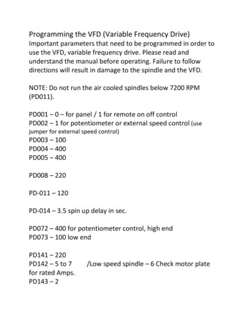
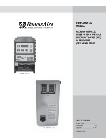
SUPPLEMENTALMANUALFACTORY-INSTALLEDLENZE AC TECH VARIABLEFREQUENCY DRIVES (VFD)IN RENEWAIRE(ERV) VENTILATORSLENZE AC TECH VFDTABLE OF CONTENTSVFD KEYPADS IN E-BOXProduct info . 2Installation . 3-9Operation. 10-16RENEWAIRE.COM
LENZE AC TECH VARIABLE FREQUENCY DRIVESPRODUCT INFOABOUT LENZE AC TECH VFDSThis manual supplements RenewAire’s standard Installation & Operation Manuals, which do not includeinformation on units equipped with ACTech/Lenze VFDs. RenewAire uses ACTech/Lenze VFDs for somemodels, typically those using a 575VAC power supply.FOR COMPLETE ERV INSTALLATION YOU WILL ALSO NEED: Standard Installation and Operation Manual for the ERV – physical installation and duct connection,maintenance procedures, etc. Supplemental Wiring Schematic Manual – complete unit wiring diagrams. SMVector-Frequency Inverter Operating Instructions – Lenze AC Tech’s users/installers manual.More information is available online in the Technical Library at www.lenze-actech.com.PLANNINGYOUR INSTALLATIONWARNINGRISK OF FIRE, ELECTRIC SHOCK, OR INJURY. OBSERVE ALL CODES AND THE FOLLOWING:1. Before servicing or cleaning the unit, switchpower off at disconnect switch or service paneland lock-out/tag-out to prevent power frombeing switched on accidentally. More than onedisconnect switch may be required tode-energize the equipment for servicing.2. This installation manual shows the suggestedinstallation method. Additional measures maybe required by local codes and standards.3. Installation work and electrical wiring must bedone by qualified professional(s) in accordancewith all applicable codes, standards andlicensing requirements.4. Any structural alterations necessary for installationmust comply with all applicable building,health, and safety code requirements.5. This unit must be grounded.6. Use the unit only in the manner intended by themanufacturer. If you have questions, contactthe manufacturer.7. When cutting or drilling into unit, wall orceiling, do not damage electrical wiring andother hidden utilities.8. Do not re-wire the VFD(s) to control more thanone motor per VFD.9. Do not operate the motors in this unit abovethe motor’s rated full load amps (FLA) asindicated on the unit’s nameplate.NOTE: VFD(s) in this unit can be operated in many ways. This Manual provides only an outline of common methods.CAUTIONDO NOT OPERATE VFD IN CONDITIONS OUTSIDE OF TEMPERATURE LIMITS. The manufacturer’sambient temperature limits for the VFDs are 14 to 131 F. It is not recommended that the VFDs be usedunder conditions above or below these temperature limits. Operate outdoor ERV units continuouslyif outdoor design conditions are not within the VFD operating temperature range or make otherprovisions to bring the VFD operating condition into the acceptable ambient temperature range.RenewAire commercial ERVs are VFD ready, in extreme climates consider field installing VFDs in aclimate controlled indoor electrical cabinet.2RENEWAIRE.COM LENZE AC TECH VFD SUPPLEMENTAL MANUAL 1.800.627.4499
LENZE AC TECH VARIABLE FREQUENCY DRIVESINSTALLATION“ON” AND “SPEED” SIGNALSVFD operation in this unit is dependent on two signals: an ON signal and a SPEED (or REFERENCE) signal.The sources and types of these signals can vary. If the ERV is equipped with dampers the ON signal to theVFD comes from the end switch on the damper. If the ERV is not equipped with dampers, the ON signalcomes from an external control connected directly to the VFD. When an ON signal is received by the VFD,it starts the motor. The VFD then operates the blower at the speed established by the SPEED signal. TheSPEED signal is often provided by an external control, but in some applications “pre-set” speeds are setinside the VFD and are selected by external switches or relays.PLANNING YOURINSTALLATIONPRINCIPLES OF EXTERNAL CONTROLThis ERV can be operated by various external control devices including remote switch or relay, digital timeclock with relay, occupancy sensor with relay, and carbon dioxide sensor with relay and analog output.These devices are commonly known as 2-wire, 3-wire, and 4-wire devices. A Building ManagementSystem (BMS) can control this ERV through relay contacts and with 0-10vdc or 4-20mA analog inputs.The external control devices can be connected to this ERV to operate each blower independently orfor one blower to act as leader and the other blower to act as follower. In leader-follower mode, a singleexternal switch or relay calls for operation and the leader VFD sets SPEED to internal presets, or inresponse to an analog input signal. The follower VFD then operates at either exactly the same speed, at anoffset above or below the leader’s speed, or at a scaled speed.The VFD’s are pre-programmed at the factory so only a few parameters need change for a specific installation.CONNECTING EXTERNAL CONTROLSIf this ERV is equipped with damper(s), the ON signal is connected to the terminal strip in the electricalenclosure (“E-box”). If this ERV is not equipped with damper(s), and has 2 VFDs, the ON signal isconnected directly to the VFDs. The SPEED signals are always connected directly to the VFD(s).WIRE ROUTINGRoute input power cables, motor cables and control cables separately to decrease electromagneticinterference caused by the rapid changes in the drive output voltage. Where control cables must crosspower cables make sure that they are arranged at an angle as near to 90 degrees as possible.Power cables and control cables can be brought into the bottom of the electrical box attached to the ERVunit or through the bottom of the unit itself. There are plugged holes to run control wires and power wiresbetween the electrical box and the unit interior, marked on the interior of the ERV unit and another pluggedhole in the unit compartment divider to run wires to VFDs in the other airstream compartment if needed.In some configurations the VFD and/or VFD protective guard may need to be removed to access the controlwire hole plug to run wires. A label is located in the ERV on the left interior wall indicating the power andcontrol wire hole plug locations. Bring wires out from the top or bottom of the VFD mounting bracket andnot through the mounting bracket window when routing wires if the VFD is mounted over the hole plug.After the wires are run, apply caulk around the wires at wire bushings used between the electrical box andERV unit and between compartments in the unit to prevent air leakage between these compartments.RENEWAIRE.COM LENZE AC TECH VFD SUPPLEMENTAL MANUAL 1.800.627.44993
LENZE AC TECH VARIABLE FREQUENCY DRIVESINSTALLATIONPLANNING YOURINSTALLATIONPURPOSE OF PROVIDED KEYPADEach VFD has a keypad which is accessible at theE-box while the unit is operating.You can check the status of the VFD at the keypad,and make changes to the VFD parameters at thekeypad. You can manually control the VFD from thekeypad during start-up and commissioning.VFD is factory programmed to cover most needsbut some parameters will need to be set tointeract with the external control system.Access the keypad(s) through the removablecover to the E-box.LENZE AC TECH KEY PAD StopRunTECHNICAL SUPPORT4For questions about applications not covered inthis manual, and for questions specific to theLenze AC Tech Drives, contact Lenze AC TechTechnical Support at 800-217-9100 or(508) 278-9100.Lenze AC Tech manuals are available as PDFs atwww.lenze-actech.com; select Technical Library.Lenze AC Tech offers training courses on theirVFDs; navigate to www.lenze-actech.com/drivesand select Training Schools.A listing of Lenze AC Tech support and servicecontacts can be found on the Internet at www.lenzeactech.com/drives and selecting Supportand Library.For questions about applications covered in thismanual, and for questions about how the VFDsare installed in your RenewAire ERV unit, contactRenewAire Customer Support at 800-627-4499.RENEWAIRE.COM LENZE AC TECH VFD SUPPLEMENTAL MANUAL 1.800.627.4499
LENZE AC TECH VARIABLE FREQUENCY DRIVESINSTALLATION“ON” SIGNAL CONNECTIONSWIRING OPTIONSDepending on features installed, connect ON-SIGNAL connections either to the VFDs themselves, or tothe low-voltage terminal strip in the ERV E-box. See schematics below.Install a jumper between terminals 2 and 3 to use the ERV’s on-board 24VAC power. Do this when theexternal control(s) have isolated contacts that don’t provide any voltage, as in the top two examples.Make no connections between terminals 1 & 2 and terminals 3-5 if the external control has a voltageoutput to provide the ON signal. This voltage must be 24VAC.WARNINGCapacitors in VFDsRetain ChargeAllow 3 minutes after shuttingoff power to the VFDs to allowthe capacitors in the VFD tofully discharge. Do not connector disconnect wires at the VFDwithout waiting 3 minutes.WIRING SCHEMATICSF1CONNECTION OF ON SIGNALS TO LOW-VOLTAGE TERMINAL STRIP IN ERV E-BOX.RENEWAIRE.COM LENZE AC TECH VFD SUPPLEMENTAL MANUAL 1.800.627.44995
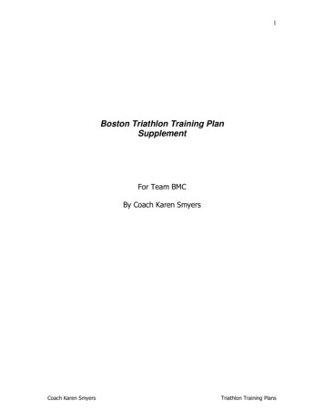
LENZE AC TECH VARIABLE FREQUENCY DRIVESINSTALLATIONFACTORY CONTROL WIRING: ON SIGNALS CONNECTED TO EACH VFD. See Fig. 1 for Relay or Damper ActuatorConnection alternatives.&20 ,1 GF Y ,1 P D 6SHHG E 6SHHG NOTE:ERV may optionally have only one VFD.'2 127 &211(&7 32:(5 72 7(50,1 /6 F6SHHG 6SHHG ,1 GF Y ,1 P D 6SHHG E 6SHHG F6SHHG 6SHHG ALTERNATIVE CONTROL WIRING: ON SIGNAL CONNECTED DIRECTLYTO ONE VFD, PASSED TO SECOND VFD FROM TERMINALS 16 & 17.&20 ,1 GF Y ,1 P D 6SHHG E 6SHHG '2 127 &211(&7 32:(5 72 7(50,1 /6 F6SHHG 6SHHG 6SHHG ,QSXW :LULQJ 1RW 6KRZQ Close contact to turn FA Blower ON. &20 ,1 GF Y ,1 P D 6SHHG E 6SHHG 9)' ) 6SHHG ,QSXW :LULQJ 1RW 6KRZQ F6SHHG 6SHHG 9)' ( F3 &20 9)' ) F29)' ( WIRING SCHEMATICS,QVWDOO WKHVH ZLUHV ) 9)' ZLOO WXUQ ( %ORZHU 21 3 5 0(7(5 6(77,1*6 ) 9)'3DUDPHWHU3 6RENEWAIRE.COM LENZE AC TECH VFD SUPPLEMENTAL MANUAL 1.800.627.44996HWWLQJ 5813DUDPHWHU 'HVFULSWLRQ&ORVHV FRQWDFW EHWZHHQ ZKHQ 9)' LV FDOOHG WR 581
LENZE AC TECH VARIABLE FREQUENCY DRIVESINSTALLATIONANALOG INPUTS TO PROVIDE THE SPEED SIGNALWIRING SCHEMATICSAnalog inputs are connected as shown below. It may be necessary to scale the response of the VFD to theanalog SPEED signal.NOTE: All wiring for analog signals connected to the VFDs should be double- or single-shielded twisted-paircable. Ground the shield at one end of the cable only. The grounding clamp on the VFD may be used.F4EXAMPLES OF ANALOG INPUT CONNECTIONS.Signal cable shield grounded2COMAnalog Speed Input Common (ground)55AIN dcAnalog Speed Input (0-10vdc)6 10v25AIN mA0-10vdc CONTROLLER0-10vdc CONTROLLER13a Speed 1Connections for 0-10vdc Controller.13b Speed 213c Speed 3301VFD (0-10vdc)2Reference Voltage ( 10vdc)-Aout41617Relay Contact or Actuator End Switch(Factory Wired)Signal cable shield groundedCOMAnalogo Speed Input Common (ground)5AIN dc-6 10v25AIN mA13a Speed 1Connections for 4-20mA Controller.13b Speed 213c Speed 330VFD (4-20mA)4-20mA CONTROLLER2Analog Speed Input (4-20mA)-PARAMETER SETTINGS - 0-10vdc ANALOG INPUTParameterP2011416ParameterF51Parameter DescriptionEnalbles use of 0-10vdc input.PARAMETER SETTINGS - FA VFD17Relay Contact or Actuator End Switch(Factory Wired)WIRING TWO VFDS FORLEADER-FOLLOWER OPERATIONSettingAoutP201Setting0Parameter DescriptionEnables use of 4-20mA inputLEADER-FOLLOWER CONNECTION.One VFD can provide the SPEED signal to a secondVFD, as shown below.NOTE: If the FA VFD is controlled by an analog inputsignal, it is likely that the FA VFD’s response to theanalog input will need to be scaled. See “SMVector –Frequency Inverter Operating Instructions” – Lenze/ACTech’s user’s/installer’s manual.Parameter P152 TB-30 Scaling Frequency can be usedto scale the Analog Output of the Leader VFD in order tooffset or correct the speed of the Follower VFD.If both VFDs are to run at the same speed, no scalingparameters need be applied to the EA VFD since it iscontrolled as a “Follower”.RENEWAIRE.COM LENZE AC TECH VFD SUPPLEMENTAL MANUAL 1.800.627.44997
LENZE AC TECH VARIABLE FREQUENCY DRIVESINSTALLATIONWIRING SCHEMATICSUSING VFD PRESETS FOR THE SPEED SIGNALSThe VFD can be programmed with 3 pre-set speeds. Switches can then be used to direct the VFD tooperate at one of those speeds. See Lenze AC Tech manuals for additional options. Leader-follower wiringcan also be used to make a second VFD operate at the same speed as the first VFD.NOTE: Pre-set speeds override any Frequency (Speed) inputs.Install Leader-Follower connection wiring if desired to operate 2nd VFD at the same speeds.F6USE OF 3 SWITCHES TO COMMAND THE VFD TO OPERATE AT ANY OF 3 PRE-SET SPEEDS (SP4T SWITCH CAN ALSO BE USED). &20 ,1 GF Y ,1 P D 6SHHG &ORVH FRQWDFW IRU 3UHVHW 6SHHG &ORVH FRQWDFW IRU 3UHVHW 6SHHG 9)'&ORVH FRQWDFW IRU 3UHVHW 6SHHG 3UHVHW E 6SHHG 3UHVHW F6SHHG 3UHVHW RXW 3 5 0(7(5 6(77,1*63DUDPHWHU3 6HWWLQJ 3DUDPHWHU 'HVFULSWLRQ(QDEOHV RSHUDWLRQ DW 3UHVHW 6SHHG 3 (QDEOHV RSHUDWLRQ DW 3UHVHW 6SHHG 3 (QDEOHV RSHUDLWRQ DW 3UHVHW 6SHHG 'R QRW GLVFRQQHFW IDFWRU\ ZLULQJ IURP 7HUPLQDOV WR 5HOD\ &RQWDFW FWXDWRU (QG 6ZLWFK RU H[WHUQDO 21 &RQWDFW The desired preset speeds are set at Parameters P131-P133. AC Tech allows up to 7 presets.Values as shipped from factory are shown below:8PARAMETERSVALUE AS SHIPPED FROM RENEWAIREPARAMETER DESCRIPTIONP13130 HzPreset Speed #1P13245 HzPreset Speed #2P13360 HzPreset Speed #3RENEWAIRE.COM LENZE AC TECH VFD SUPPLEMENTAL MANUAL 1.800.627.4499
LENZE AC TECH VARIABLE FREQUENCY DRIVESINSTALLATIONUSE WITH A CO2 CONTROLLERWIRING SCHEMATICSIf both VFDs are to run at the same speed, no scaling parameters need be applied to the EA VFD in thisexample since it is controlled as a “Follower”. If it is required that the VFDs shut off when CO2 levels dropbelow a setpoint, connect the Normally O
6 renewaire.com lenze ac tech vfd supplemental manual 1.800.627.4499 f2 factory control wiring: on signals connected to each vfd. wiring schematics installation see fig. 1 for relay or damper actuator connection alternatives. note: erv may optionally have only one vfd. f3 alternative control wiring: on signal connected directly to one vfd, passed to second vfd from terminals 16 & 17.,qvwdoo .