Transcription
—MNS iS motor control centerSystem guide—MNS iS motor control centerSystem guide
—Table of contents—MNS iS system overviewMNS iS – Value insideMNS iS – Innovative designFunction module conceptComponents overview—MNS iS design aspectsSwitchboard constructionFunctional compartmentsand segregationSwitchboard arrangementsFrame constructionEnclosureCable compartmentsBusbar systemsMNS iS power modules MStartModule connection to distribution barsIncoming feeders and bus couplers—MNS iS user interfaceIntegration into plant wide monitoringand control systemsInterrogation and operationParameterization and engineering—MNS iS communicationCommunication interfaceTime synchronisationDual redundancy4–845–67810 – 2210111213131415– 1718– 1920– 212224 – 2624252627 – 29272829—MNS iS control and protectionMStart – motor starter power moduleMControl – motor starter control unitI/O interfacesModular software applicationProtection function modulesMaintenance function moduleSystem statusMeasurements and monitoringAdditional function modules30 – 403031323334– 3637383940—After sales and service41 – 42—MNS iS technical dataMNS iS mechanical andelectrical characteristicsMNS iS standards and approvalsMNS iS switchboard dimensionsModule types and dimensionsModule selection tablesControl and communicationcomponentsCertificates—AnnexItems subject to agreement betweenmanufacturer and user43 – 534344454647– 5051– 525354 – 55
—ABB’s innovative MNS iS conceptcombines the long term experience,energy efficiency, grid reliability andindustrial productivity of the well knownMNS system with advanced design inhardware and software technologies.
M N S I S – VA LU E I N S I D E4—MNS iS system overviewMNS iS – Value insideHigh protection and safetyMNS iS and its clear segregation of power andcontrol compartments offers highest personal,system and supervision safety possibilities.Pro-active maintenanceMNS iS with Condition Monitoring indicatesconditions before a failure occurs, enablingpro-active maintenance possibilities.StandardizationMaximum simplicity due to standardized powermodules – fully assembled and ready to use fora wide range of motor starter and energydistribution modules.User friendlinessMNS iS provides integrated user tasks, likemodule supervision, lifecycle management,contact temperature supervision andpower loss supervision.Lower lifecycle costsThese are defined in three ways; less downtime,less fault finding and less inventory.Less engineering complexityMNS iS is the easiest way to plan, engineer andmanage a low voltage switchgear system.Information varietyMNS iS offers latest HMI technology, remotemanagement, innovative plug and producetechnology and real time plant conditionmonitoring.Project implementationMNS iS helps you to reduce your project costs byoffering a shorter project duration due to highstandardization and reduced engineering.Complete solutionABB offers the possibility to provide an all inone solution when MNS iS is used in conjunctionwith other power and automation technologiesfrom ABB.
5MNS IS MOTOR CONTROL CENTER S YSTEM GUIDE—MNS iS system overviewMNS iS – Innovative designMNS iS retains the best of MNS technology andevolves it into the next level of operationalhandling benefits for customers’ low voltagemotor control center applications.Flexible control modulesScalable for basic to complex motor starter types,protection functions and field input/outputsignal requirements.The distinct elements in MNS iS are:Integrated control schematicsAll starter level interlocking scheme betweencontrol and power module is built in.No hardwiring or input/output assignmentrequired. The control schematic is reduced toassigning field I/O signal contacts only.Power and control part operational safetyPhysically separated and independentoperational handling of power andcontrol parts.Standard power modulesFully assembled, ready to use and offered fora wide range of motor starter and energydistribution modules.
M N S I S – I N N O VAT I V E D E S I G NMeasurement variablesSelectable temperature, current and voltagemeasurement for various protection needsfor both motor and the switchgear itself.No traditional transformers are utilizedfor any measurements.Information distribution as requiredIndustry standard communication interfaces,such as Profibus DP, ProfiNet, Modbus RTU,Modbus TCP and OPC are available, enabling sitewide distribution of information (operator,maintenance, management).6System accessibility with ‘off the shelf’web browser based devicesWith an inbuilt web server functionality, the usercan select any web browser based device tointerrogate the system.User friendlinessSelf supervision of module location, module type,power rating and automatic installation onto thecommunication network.
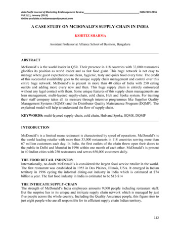
MNS IS MOTOR CONTROL CENTER S YSTEM GUIDE7—MNS iS system overviewFunction module conceptMNS iS motor control center solution deliversall the functions for control, protection andmonitoring of the motors and motor startersusing software and hardware modules for thespecific tasks. Right information is provided tothe right people at the right time.Hardware modules are designed to fulfill desiredtasks (power module containing electrical partse.g. to isolate power, control module containingsoftware applications etc. to control a motor).System functions are provided as functionalmodules to be downloaded to the control module.Only required functions are downloaded whileothers are available as options.System functionality may be enhanced at anytime without the requirement for additionalhardware or wiring.Module and location supervision are availableas a standard. These functions ensure thecorresponding power and control modules areinstalled to the correct location for the particularmotor/feeder application.Maintenance functions are an integral part ofthe system. Asset monitors measuring systemperformance data (e.g. outgoing linetemperature, number of insertions) allowscheduling of maintenance activities only ifthey are really required.The flexibility of the system allows modificationsby a simple “plug and produce” concept.Exchanging the modules or changing theparameter settings is easily achieved by usingsystem inherent functions and tools.Time synchronization with a time server in theplant or locally in the switchboard allows accuratetime stamps of alarms and events collected in thecontrol module.Process Control SystemFieldbusSwitchgear Control NetworkMLink 1Communication I/F;Web Server; Time CientMViewWeb InterfaceMLink nCommunication I/F;Web Server;Time CientMControl 1Control andProtectionMControl 1Control andProtectionMControl nControl andProtectionMControl nControl andProtectionMControl 60Control andProtectionMControl 60Control andProtection
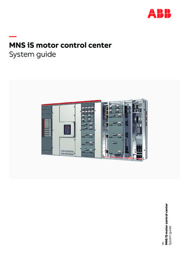
COMPONENTS OVERVIE W8—MNS iS system overviewComponents overviewThe power module MStart/MFeed comprises: The electrical isolator. The short circuit protection device (fuses orcircuit breaker). Contactor and any electrical control equipmentand status indication. The sensor module (measuring the electricalvalues, which are then available to the processvia the MControl module).The integrated motor controller module MControl(located in the control compartment) comprises: The processor performing all the protection,control functions and monitoring functions. Itexchanges information with the MStart/MFeedvia an internal bus.MView I/O interface modules providing an interface toexternal components for control, protectionand indication.The interface module MLink serves as thegateway to higher level systems whichcommunicate via the internal bus toall MControl modules.A local human system interface MView is availableto monitor the MNS iS status and displayinformation on each connected motor/feeder.MLinkControl condapterMControlPower condapterMStart/MFeed
9MNS IS MOTOR CONTROL CENTER S YSTEM GUIDE
S W I TC H B O A R D C O N S T R U C T I O N10—MNS iS design aspectsSwitchboard constructionMNS iS as part of the ABB low voltage switchgearsolution uses the well proven ABB MNS standarddesign aspects. MNS aspects described in thissection are fully applicable to MNS iS.MNS system is a verified low voltage switchgeardesign in accordance with IEC 61439 series andIEC 61641.The consistent application of the modularprinciple both in electrical and mechanical designas well as the use of standardized componentsallows its flexible and compact design.Depending on operating and environmentalconditions different design levels are offered.Notable system advantages with regard todesign aspects: Optimum personal protection Design verified by testing Arc fault containment acc. criteria 1-7 High operational reliability and availability Earthquake-, vibration- and shock-proofdesigns are available Maintenance-free busbar construction Simple retrofitting procedures Compact, space-saving design Easy project and detail engineering throughstandardised components
11MNS IS MOTOR CONTROL CENTER S YSTEM GUIDE—MNS iS design aspectsFunctional compartmentsand segregationThe switchboard is divided into vertical andhorizontal compartments thus separatingdifferent functional areas.4As a standard, power cabling and control wiringare strictly separated within MNS iS. Theswitchboard is structured as follows:1 Equipment compartmentAll equipment, including the standard motorstarter modules (MStart) in withdrawabledesign, is situated therein. The compartmentcan be divided in horizontal and verticalsub-compartments.2 Control cable compartmentContains the motor control devices(MControl), control cables and terminals.3 Power cable compartmentContains power cables and connection units.4 Busbar compartmentContains the MNS main busbar system anddistribution bars. The distribution bars areembedded in the multifunction separationwall (MFW) which is located between theequipment compartment and the busbarcompartment.1—Incomer42System highlights Functional areas are separated from each otherin accordance with IEC 61439 series. Power cables are fully separated from the control and communication cables, thus avoidingelectromagnetic interferences. Different access rights to cable compartmentscan be granted using different key locks.31—MCC
S W I TC H B O A R D A R R A N G E M E N T S12—MNS iS design aspectsSwitchboard arrangementsMNS iS cubicles can be arranged as follows: In standard execution (back-to-wall) Back-to-back DuplexFor switchgear dimensions,see Technical Data section.—Standard (Back-to-wall)—Back-to-back—Duplex (common busbar compartment)
13MNS IS MOTOR CONTROL CENTER S YSTEM GUIDE—MNS iS design aspectsFrame constructionThe basic elements of the MNS iS frameconstruction are “C” shaped steel profiles witha 25 mm hole pitch according to DIN 43660.This 25 mm equals the dimension of 1E usedin MNS to define the area usage withinthe switchgear.Each cubicle is precision constructed by boltinghorizontal and vertical profiles together, to forma rigid modular structure. The assembly ismaintenance free as a result of the constructionmethod utilizing a combination of thread lockingESLOK screws with bolted pressure plates andthread forming screws.The profiles are galvanic protected (Zn or AL/Zn)against corrosion.—MNS iS Design AspectsEnclosureMNS iS switchboard enclosure is made of sheetsteel protected by galvanic coating and powdercoating for maximum durability.The fixing of the enclosure with respect to doors,roof plates, rear and side walls is achieved withthread forming screws. Final construction variesdepending upon the required degree ofprotection.In accordance with the general safety philosophyfollowed with MNS iS, each compartment andsub-compartment which requires access forcommissioning, operation or maintenance,has its own door.
C A B L E C O M PA R T M E N T S14—MNS iS design aspectsCable compartmentsAccess to components such as electronicprotection relays within standard switchgear isusually not possible if the module is energized.This control compartment houses the scalablemotor control units MControl and serialcommunications bus cables.As an innovative design attribute MNS iSswitchgear provides separate compartments,one for power cables on the right hand andanother for control cables on the left hand. Thetwo cable compartments can be provided withdifferent key locks in order to assure specificaccess rights.The control wiring can enter from the top orbottom as required for the project.Cable compartment separation is available as anoption up to Form 4, as shown below.Control cable compartmentThe control cables have their own control cablecompartment completely segregated from thepower compartment.Power cable compartmentMNS iS motor/feeder cables are housed in theirown power cable compartment completelyisolated from any control equipment or wiring.The cubicle arrangements are configured suitablefor front cable access.The power cable compartment can be providedwith cable entry from the top or bottom of thecubicle.
15MNS IS MOTOR CONTROL CENTER S YSTEM GUIDE—MNS iS design aspectsBusbar systemsMain busbarsThe MNS main busbar system is arranged in therear of the switchgear. This assures a maximumdistance from the busbars to the operator andmaintenance staff. The main busbar system isfully separated from the equipment compartmentas well as from the cable compartments.The busbar system is a maintenance freeconstruction as a result of utilizing threadlocking ESLOK screws together with conicalspring washers.This technology remains relatively unchangedsince the introduction of MNS, and has beenextensively supplied into the most demandingindustries.The busbar system and all associated parts aremanufactured from copper in accordance withDIN 40500. Options are available for silver platingand/or fully insulated solution utilizing heatshrinkable sleeving.
BUSBAR SYSTEMSProtective earth and neutral barsAs a standard, protective earth and neutral barsrun horizontally in the front of the switchboardjust above the base.
Scalable for basic to complex motor starter types, protection functions and field input/output signal requirements. Integrated control schematics All starter level interlocking scheme between control and power module is built in. No hardwiring or input/output assignment required. The control schematic is reduced to assigning field I/O signal contacts only. MNS IS – INNOVATIVE DESIGN 6 .