Transcription
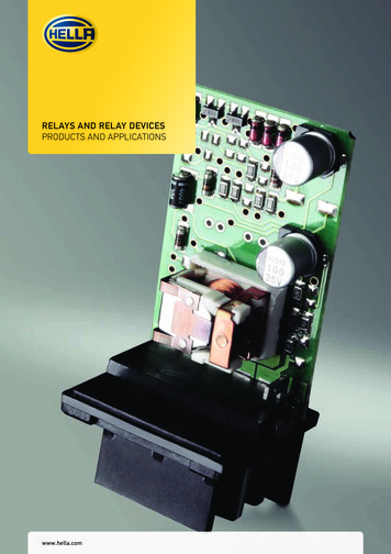
RELAYS AND RELAY DEVICESPRODUCTS AND APPLICATIONSwww.hella.com
INTRODUCTION
2 3INTRODUCTION2A small component with a big history . . . . . . . . . . . . . . . . . . . . . . . . . . . . . . . . . . . . . . . . . . . . . . . . . . . . 4How HELLA checks and ensures quality . . . . . . . . . . . . . . . . . . . . . . . . . . . . . . . . . . . . . . . . . . . . . . . . . . 7ELECTROMECHANICAL RELAYS8Explanation and uses . . . . . . . . . . . . . . . . . . . . . . . . . . . . . . . . . . . . . . . . . . . . . . . . . . . . . . . . . . . . . . . . . . 8Relay types . . . . . . . . . . . . . . . . . . . . . . . . . . . . . . . . . . . . . . . . . . . . . . . . . . . . . . . . . . . . . . . . . . . . . . . . . . 12Mini relay 12 V – make contact with holder . . . . . . . . . . . . . . . . . . . . . . . . . . . . . . . . . . . . . . . . . . . . . . 13Mini relay 12 V, make contact without holder . . . . . . . . . . . . . . . . . . . . . . . . . . . . . . . . . . . . . . . . . . . . . 14Mini relay 12 V, change-over contact with holder. . . . . . . . . . . . . . . . . . . . . . . . . . . . . . . . . . . . . . . . . . 15Mini relay 12 V, make contact without holder . . . . . . . . . . . . . . . . . . . . . . . . . . . . . . . . . . . . . . . . . . . . . 16Mini relay 24 V – make contact with holder . . . . . . . . . . . . . . . . . . . . . . . . . . . . . . . . . . . . . . . . . . . . . . 17Mini relay 24 V, make contact without holder . . . . . . . . . . . . . . . . . . . . . . . . . . . . . . . . . . . . . . . . . . . . . 18Mini relay 24 V, change-over contact with holder. . . . . . . . . . . . . . . . . . . . . . . . . . . . . . . . . . . . . . . . . . 19Mini relay 24 V, make contact without holder . . . . . . . . . . . . . . . . . . . . . . . . . . . . . . . . . . . . . . . . . . . . . 20MICRO RELAY22Micro relay 12V, make contact without holder / change-over contact without holder . . . . . . . . . . 22Micro relay 24V, change-over contact without holder . . . . . . . . . . . . . . . . . . . . . . . . . . . . . . . . . . . . . . 23HIGH POWER RELAY24High-power relay 12V, make contact with holder/without holder . . . . . . . . . . . . . . . . . . . . . . . . . . . 24High-power relay 24V, make contact with holder/without holder . . . . . . . . . . . . . . . . . . . . . . . . . . . 25BATTERY DISCONNECT RELAY/SOLID STATE RELAY26Battery disconnect relay and solid state relay 12V, make contact . . . . . . . . . . . . . . . . . . . . . . . . . . . 26Summary of battery disconnect and solid state relays . . . . . . . . . . . . . . . . . . . . . . . . . . . . . . . . . . . . . 27TECHNICAL DATA28Technical data of the relays – Overview . . . . . . . . . . . . . . . . . . . . . . . . . . . . . . . . . . . . . . . . . . . . . . . . . . 28Climatic and mechanical tests . . . . . . . . . . . . . . . . . . . . . . . . . . . . . . . . . . . . . . . . . . . . . . . . . . . . . . . . . . 30FLASHER UNITS32Explanation and uses . . . . . . . . . . . . . . . . . . . . . . . . . . . . . . . . . . . . . . . . . . . . . . . . . . . . . . . . . . . . . . . . . 32Test circuits . . . . . . . . . . . . . . . . . . . . . . . . . . . . . . . . . . . . . . . . . . . . . . . . . . . . . . . . . . . . . . . . . . . . . . . . . . 36Flasher unit 6V, 4-pole and 12V, 3-pole . . . . . . . . . . . . . . . . . . . . . . . . . . . . . . . . . . . . . . . . . . . . . . . . . . 38Flasher unit 12V, 3-pole . . . . . . . . . . . . . . . . . . . . . . . . . . . . . . . . . . . . . . . . . . . . . . . . . . . . . . . . . . . . . . . 39Flasher unit 12V, 4-pole . . . . . . . . . . . . . . . . . . . . . . . . . . . . . . . . . . . . . . . . . . . . . . . . . . . . . . . . . . . . . . . 40Flasher unit 12V, 5-pole/6-pole . . . . . . . . . . . . . . . . . . . . . . . . . . . . . . . . . . . . . . . . . . . . . . . . . . . . . . . . 41Flasher unit 12V, 6-pole/7-pole . . . . . . . . . . . . . . . . . . . . . . . . . . . . . . . . . . . . . . . . . . . . . . . . . . . . . . . . 42Flasher unit 24V, 3-pole/4-pole . . . . . . . . . . . . . . . . . . . . . . . . . . . . . . . . . . . . . . . . . . . . . . . . . . . . . . . . 43Flasher unit 24V, 4-pole/5-pole . . . . . . . . . . . . . . . . . . . . . . . . . . . . . . . . . . . . . . . . . . . . . . . . . . . . . . . . 44Flasher unit 24V, 6-pole/7-pole . . . . . . . . . . . . . . . . . . . . . . . . . . . . . . . . . . . . . . . . . . . . . . . . . . . . . . . . 45Flasher unit 24 V, 11-pole and 12/24 V, 6-pole . . . . . . . . . . . . . . . . . . . . . . . . . . . . . . . . . . . . . . . . . . . 46LED flasher unit 12/24V, 3-pole; 12V, 4-pole/5-pole and 24V, 4-pole . . . . . . . . . . . . . . . . . . . . . . . . 47Overview of flasher unit technical data . . . . . . . . . . . . . . . . . . . . . . . . . . . . . . . . . . . . . . . . . . . . . . . . . . 48Legal regulations for flasher units . . . . . . . . . . . . . . . . . . . . . . . . . . . . . . . . . . . . . . . . . . . . . . . . . . . . . . 48LED indicators and failure control from HELLA . . . . . . . . . . . . . . . . . . . . . . . . . . . . . . . . . . . . . . . . . . . 49The right solution for your vehicle electronics . . . . . . . . . . . . . . . . . . . . . . . . . . . . . . . . . . . . . . . . . . . . 50WASH/WIPE INTERVAL CONTROL UNITS52Explanation and uses . . . . . . . . . . . . . . . . . . . . . . . . . . . . . . . . . . . . . . . . . . . . . . . . . . . . . . . . . . . . . . . . . 52Wash/wipe interval control units 12V . . . . . . . . . . . . . . . . . . . . . . . . . . . . . . . . . . . . . . . . . . . . . . . . . . . 54Wash/wipe interval control units 24V . . . . . . . . . . . . . . . . . . . . . . . . . . . . . . . . . . . . . . . . . . . . . . . . . . . 55Headlight cleaning system 12V/24V . . . . . . . . . . . . . . . . . . . . . . . . . . . . . . . . . . . . . . . . . . . . . . . . . . . . . 56CLOCK RELAYS58Explanation and uses . . . . . . . . . . . . . . . . . . . . . . . . . . . . . . . . . . . . . . . . . . . . . . . . . . . . . . . . . . . . . . . . . 58Clock relays 12V . . . . . . . . . . . . . . . . . . . . . . . . . . . . . . . . . . . . . . . . . . . . . . . . . . . . . . . . . . . . . . . . . . . . . . 60Clock relays 24V . . . . . . . . . . . . . . . . . . . . . . . . . . . . . . . . . . . . . . . . . . . . . . . . . . . . . . . . . . . . . . . . . . . . . . 61ACCESSORIES62Overview . . . . . . . . . . . . . . . . . . . . . . . . . . . . . . . . . . . . . . . . . . . . . . . . . . . . . . . . . . . . . . . . . . . . . . . . . . . . 62SWITCHING AND PLUG MATRICES64Circuit diagrams – electromechanical relays . . . . . . . . . . . . . . . . . . . . . . . . . . . . . . . . . . . . . . . . . . . . . 64Pin diagrams – electromechanical relays . . . . . . . . . . . . . . . . . . . . . . . . . . . . . . . . . . . . . . . . . . . . . . . . 65Pin diagrams – flasher units . . . . . . . . . . . . . . . . . . . . . . . . . . . . . . . . . . . . . . . . . . . . . . . . . . . . . . . . . . . 66Pin diagrams – wash/wipe interval control units . . . . . . . . . . . . . . . . . . . . . . . . . . . . . . . . . . . . . . . . . 67Pin diagrams – clock relays . . . . . . . . . . . . . . . . . . . . . . . . . . . . . . . . . . . . . . . . . . . . . . . . . . . . . . . . . . . . 67Pin diagrams – control units for headlight cleaning systems . . . . . . . . . . . . . . . . . . . . . . . . . . . . . . . 67HELLA ROCKER SWITCHES68The new HELLA switch configurator . . . . . . . . . . . . . . . . . . . . . . . . . . . . . . . . . . . . . . . . . . . . . . . . . . . . 68Rocker switch, 3100 series. . . . . . . . . . . . . . . . . . . . . . . . . . . . . . . . . . . . . . . . . . . . . . . . . . . . . . . . . . . . . 70Switch functions . . . . . . . . . . . . . . . . . . . . . . . . . . . . . . . . . . . . . . . . . . . . . . . . . . . . . . . . . . . . . . . . . . . . . . 71
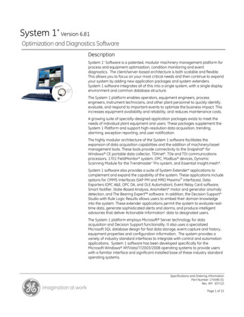
INTRODUCTIONA small component with a big historyRelays have been used to remotely control circuits for over 180 years. The technology has proven itsreliability millions of times and is today still the first choice for many applications, such as in automotiveengineering.From the telegraph to automotive engineeringQuality relays from HELLA – versatile and reliable The relay owes its name to former times when mail was stillcarried by horse. At what were known as relay stations, postriders could swap their horses for rested ones. Today, we callan electromagnetic, remotely operated switch a relay. Manufacturing expertise:HELLA produces more than 100 million units per year at itsown facilities – thanks to optimised production at an attractiveprice and with one of the lowest failure rates in the entireindustry. The American physician Joseph Henry invented the electricrelay in 1835. The pioneer in communications engineeringused it to send messages from his laboratory to his home.Relays were first used on a larger scale in 1837, as signalamplifiers for Samuel Morse’s recording telegraphs. Theywould later make possible the widespread use of telephonesand became a cornerstone of safety in railway engineering. In1941, Konrad Zuse utilised 2,000 relays in his legendary Z3, thefirst digital computer. HELLA produced its first automotiverelay in 1960. As electronics matured in the 20th century, the age of the relaywas often seen as over; nevertheless, they retain a place inspecific applications. The automotive industry, for example,needs relays, since relay functions cannot always be replacedby control units. Only relays make galvanic isolation possiblebetween input and output. Semi-conductors cannot managethis at the moment. The cost advantage relays have overelectronic solutions is also unbeatable. Relays are used in automotive engineering to switch highcurrents. The engine control unit, for example, is switched by arelay. Because relays are robust and not particularlysusceptible to failure, they can be installed near electricdevices. They require only low control currents, making smallline cross-sections sufficient. The switching and amplifierfunction of a relay could only be achieved with a lot more effortand a lot less reliability using more “modern” electronics.Another benefit of the relay is that it is quick and easy toreplace. These positive characteristics are the reason whyrelays are still in use. And they ensure that, in the future, relayswill still be at home in many vehicles. Flexibility:Large volumes are produced in a fully automated process,small volumes with semi-automation. This means we are in aposition to change over quickly to semi-automatic production.HELLA is able to respond promptly to customer requirementsand create new variants in addition to its existing productrange at short notice. OEM customers:HELLA develops and produces relays for AGCO, Claas, DaimlerAG, Ford, VW, GM, JCB, Opel/Vauxhall, Nissan, John Deere,Chrysler, Jaguar/Land Rover and others. Many of ourcustomer relationships have existed for decades. Production locations:Berlin (Germany); Flora, Illinois (USA); Xiamen (China).
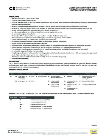
4 51951First hot-wire flasher unit19601965E-relay: the first fully electronic flasher unit19681969Micro relay: high-current and bi-stable versionIntelligent flasher units for active LED flashers with current pulse evaluation in acc. with ISO 13207-120082012Mini solid state relayBi-stable battery disconnect relay with flexible attachment system20052006Round connector relay: specially produced for Daimler AG, with plastic housingMicro relay: designed for fully automated production19982003H-relay: high-power relay for different motor loadsSounding relay for controlling direction indicator lamps19891994V-relay: PCB relay for automatic placementS1-relay: replacement for Q-relay. Can be produced fully automatically, also available with built-in fuse19781982K-relay: current controlled relay for direction indicator lampsBi-stable relay for switching between low and high beamQ-relay with plastic base plate, also available with built-in fuse19731976L-relay: the first modular systemWipe/wash interval control unit19701972A-relay with metal housing.Mechanical threshold voltage controller for windshield wipersFlasher unit with microprocessor technologyNew and refined relay products with lower power consumption to help reduce CO2 emissions
INTRODUCTION
6 7Temperature ( C)Relative humidity (%)How HELLA checks and ensures qualityTime (minutes) Design life tests:The relays are switched on/off in cycles on fully automatedtest racks. Original loads or simulated resistive, inductive,capacitive or combined loads whose current characteristics arerecorded as the original loads are connected. In addition, therelays can be subjected to different ambient temperatureranges or temperature profiles. The test is continuouslydocumented. Electrical parameters:Within the context of product release, starting voltage, dropoutvoltage, contact voltage drop, coil resistance and insulationresistance are tested, for example. Accompanying themanufacturing process, the electrical parameters are recordedat the end of the production process by end-of-line testers.These can be evaluated statistically. One important factor forguaranteeing the consistent high quality of the relaysproduced. Environmental and mechanical tests:Every relay has to pass tests such as the alternatingtemperature test, salt spray fog test, mechanical shock test ordrop test and the vibration test within the context of theproduct release process. These tests are carried out usingHELLA equipment.1) Load curve, 20 A resistive 10 A 500 ms Analytical tests:Here, the materials used and the different connectingprocesses such as soldering and welding are tested. The testsare carried out randomly during incoming goods testing andfollowing production. Certificates:Hella has been certified in a range of relevant areas e.g. DINEN ISO 9001:2008, ISO / TS 16949:2009, ISO 14001. HELLArelays also comply with the ROHS (2002/95/EC) and REAChstandards.1) Load curve, 3 x high beam 10 A 500 ms
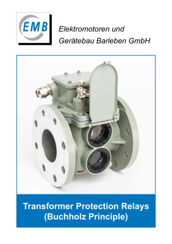
ELECTROMECHANICAL RELAYSExplanation and usesKey components of an electromechanical relayLegendContact platesBlade terminal (load) made of E-Cu (electrolytic copper)with tin-plated surfaceArmatureBlade terminal (coil) made of CuZn (brass)with tin-plated surfacePins for coil wireBase plateSwitch contactsCoil bodyCoil made of Cu wireYokeIron core (in the coil)
8 9Functional principleRelays are basically electrically operated switches which use an electromagnet to move a switching mechanism byswitching one or more contacts. They are used where one or more load circuits need to be switched on or off bymeans of a control signal. Characteristic of the electromechanical relay is the complete (galvanic) isolationbetween the control and controlled circuits.Make relaysMake relays are used to close an electric circuit between a power source and one or more electrical loads, i.e. theloads are switched on. Relays are operated by means of switches, pulse generators or control devices. Typicalvehicle applications are headlights, auxiliary lights and fog lights, horns, heaters, air conditioner systems, etc.How make relays workFig.1) The control circuit (86/85) is inactive and the return spring keeps the armature open. The make contacts areopen and the load circuit (30/87) is interrupted.Fig. 2) The control circuit (86/85) is active and the copper coil induces a magnetic field which pulls the armaturedown onto the magnetic core. The make contacts are closed and the load circuit (30/87) is therefore alsoclosed.Fig. 1Fig. 2Change-over relaysChange-over relays switch the load circuit over from one electrical load to another. These relays can be operatedby a dashboard switch, for example. Change-over relays are used for switch applications with two stages/speedssuch as heated rear windows or fan motors etc.How change-over relays workA change-over relay operates on the same principle as a make relay. The only difference is that the armature isconnected to a second (alternative) output (87a) when released. As soon as the control circuit is active, thearmature is pulled in, opens the break contact (87a) and switches over to the make contact (87). A change-overrelay can be used as either a make or a break relay. By design, the switching current of the make contact is alwayshigher than that of the break contact.Rated voltage 12 V: for passenger cars, agricultural and construction machinery etc. 24 V: for commercial vehicles, buses, municipal vehicles etc.
ELECTROMECHANICAL RELAYSRated load(depending on load type)A Resistive load:The current remains around the samefrom switch-on to switch-off (e.g. rearwindow heater).Example load curve, resistive load Inductive load:The inrush current increases to therated current with a specific delay timedue to the build-up of the inductor’smagnetic field and then levels off (e.g.switching on a solenoid switch). Duringswitch-off, a voltage of up toseveral thousand volts is (theoretically)induced, resulting in an electric arcbetween the relay contacts just opened.Example load curve, inductive load Capacitive/bulb load:The inrush current of a capacitive loador a lamp can rise to ten times the ratedcurrent before leveling off to the ratedcurrent.Example load curve, capacitive/bulb load
10 11Coil circuitIn order to prevent voltage spikes caused by mutual inductance when switching off the coil current, our relays arein part equipped with resistors or diodes parallel to the coil.Contacts and connector configurations30Load current , terminal 15 (input)85Relay coil - (input)86Relay coil (input)87Load current, make contact (output)87aLoad current, break contact (output)
ELECTROMECHANICAL RELAYSRelay typesMini relaysMini relays according to ISO 7588-1, blade terminals according to ISO 8092-1.Contact arrangements: make contact, change-over contact, max. 40 A switchingpower (make contact), rated voltage: 12 V, 24 VAreas of application include: headlights, starters, fuel pumps, fan motors, horns andfanfares.Micro relayMicro relays according to ISO 7588-3 (1988), blade terminals according to ISO 8092-1.Contact arrangements: make contact, change-over contact, max. 20 A switchingpower (make contact), rated voltage: 12 V, 24 VAreas of application include: fuel pumps, air conditioning systems, windshieldwasher systems, wiper motors.High-power relayMini relay version with larger dimensions, blade terminals according to ISO 8092-1.Contact arrangement: make contact, change-over contact, max. 60 A switchingpower, rated voltage: 12 V, 24 VAreas of application include: battery disconnect relays, starter motors, glow plugs,ignitions, windshield heating.Solid state relayMini semiconductor relays according to ISO 7588-1, blade terminals according to ISO8092-1.Contact arrangement: make contact, max. 22 A switching power (make contact),rated voltage: 12 VAreas of application include: vacuum pumps for brake booster support, daytimerunning lights.Battery disconnect relayBi-stable electromechanical relay with one or two coils.Contact arrangement: make contact, max. 180 A switching power, rated voltage: 12 VAreas of application include: disconnecting the vehicle electric system from thebattery in the event of accidents or for maintenance, retain battery charge byswitching off quiescent current
12 13 15Breakcontact 100–Makecontact –15Bulb loadBreakcontact 100–Makecontact –15Breakcontact 100––Parallel resistance [ohm]MakecontactInductive loadPart numberCoil resistance [ohm]Resistive loadCircuit diagramProduct photoPin arrangementMini relay 12 V – make contact with holderAS1085–4RA 003 530-001with fuse link15 A25100––25100––25100––AS1085–4RA 003 530-042with fuse link25 A40100––35100––30100––BS21006804RA 007 RA 007 793-041with 9.5 mm S685–4RA 933 791-061with –4RA 933 791-091with dual output andparallel diode30 100––30100––15Rated switching current (A) at 80 C ambient temperatureNumber of switching operations (thousands)100––AS190–4RA 965 400-001
MINI RELAYSCircuit diagramCoil resistance [ohm]Parallel resistance [ohm]Part numberPin arrangementMini relay 12 V, make contact without holderProduct photoResistive load40100––35100––30100––BS21006804RA 007 RA 007 793-031Makecontact Inductive loadBreakcontact Makecontact Bulb loadBreakcontact Makecontact Breakcontact with 9.5 mm 185–4RA 933 RA 933 332-151with 604RA 933 A 933 332-221with parallel diode30 100––30100––16Rated switching current (A) at 80 C ambient temperatureNumber of switching operations (thousands)100––AS190–4RA 965 400-017
14 15Circuit diagramCoil resistance [ohm]Parallel resistance [ohm]Part numberPin arrangementMini relay 12 V, change-over contact with holderProduct photoResistive load30100201002010053003010010100B1W21006804RD 007 794-0313010020100201006602010010100B1W185–4RD 933 332-0113010020100201006602010010100B1W2855604RD 933 332-031Makecontact Inductive loadBreakcontact Makecontact Bulb loadBreakcontact Makecontact Breakcontact Dust and waterproof,IP 6K7 / IP 6K9K*3010020100201006602010010100B1W185–4RD 933 332-0413010020100201006602010010100B1W185–4RD 933 332-2373010020100201006602010010100B1W385–4RD 933 332-277with parallel diode Rated switching current (A) at 80 C ambient temperatureNumber of switching operations (thousands)* in conjunction with mating connector 8JD 745 801-001/-011
MINI RELAYSCircuit diagramCoil resistance [ohm]Parallel resistance [ohm]Part numberPin arrangementMini relay 12 V, make contact without holderProduct photoResistive load30100201002010053003010010100B1W21006804RD 007 794-02130100201002010053003010010100B1W3100–4RD 007 794-041Makecontact Inductive loadBreakcontact Makecontact Bulb loadBreakcontact Makecontact Breakcontact with parallel diode30100201002010053003010010100B1W21006804RD 007 794-0773010020100201006602010010100B1W385–4RD 933 332-021with parallel diode3010020100201006602010010100B1W185–4RD 933 332-0513010020100201006602010010100B1W2855604RD 933 332-177Dust and waterproof,IP 6K7 / IP 6K9K*30100151003315020150161008100A1W395–4RD 965 400-027with parallel diode Rated switching current (A) at 80 C ambient temperatureNumber of switching operations (thousands)* in conjunction with mating connector 8JD 745 801-001/-011
16 17 15Breakcontact 100–Makecontact –15Bulb loadBreakcontact 100–Makecontact –15Breakcontact 100––Parallel resistance [ohm]MakecontactInductive loadPart numberCoil resistance [ohm]Resistive loadCircuit diagramProduct photoPin arrangementMini relay 24 V – make contact with holderAS10315–4RA 003 530-051with fuse link15 A20150––16100––16135––BS230512004RA 007 4RA 933 791-071with dual-output30 250––16100––16Rated switching current (A) at 80 C ambient temperatureNumber of switching operations (thousands)250––AS1360–4RA 965 400-031
MINI RELAYSCircuit diagramCoil resistance [ohm]Parallel resistance [ohm]Part numberPin arrangementMini relay 24 V, make contact without holderProduct photoResistive load20150––16100––16135––BS230512004RA 007 4RA 933 RA 933 4RA 933 791-081Makecontact Inductive loadBreakcontact Makecontact Bulb loadBreakcontact Makecontact Rated switching current (A) at 80 C ambient temperatureNumber of switching operations (thousands)Breakcontact
18 19Circuit diagramCoil resistance [ohm]Parallel resistance [ohm]Part numberPin arrangementMini relay 24 V, change-over contact with holderProduct photoResistive load20150101001610010100161355135B1W230512004RD 007 903-0112010010100161008100151355135B1W1350–4RD 933 332-0612010010100161008100151355135B1W3350–4RD 933 332-081Makecontact Inductive loadBreakcontact Makecontact Bulb loadBreakcontact Makecontact Breakcontact with parallel diode Rated switching current (A) at 80 C ambient temperatureNumber of switching operations (thousands)
MINI RELAYSCircuit diagramCoil resistance [ohm]Parallel resistance [ohm]Part numberPin arrangementMini relay 24 V, make contact without holderProduct photoResistive load20150101001610010100161355135B1W230512004RD 007 903-00120150101001610010100161355135B1W2305–4RD 007 903-021Makecontact Inductive loadBreakcontact Makecontact Bulb loadBreakcontact Makecontact Breakcontact with parallel diode2010010100161008100151355135B1W1350–4RD 933 332-0712010010100161008100151355135B1W3350–4RD 933 332-091with parallel diode20 1001010016100810015Rated switching current (A) at 80 C ambient temperatureNumber of switching operations (thousands)1355135B1W235012004RD 933 332-261
20 21
MICRO RELAYCircuit diagramCoil resistance [ohm]Parallel resistance [ohm]Part numberPin arrangementMicro relay 12V, make contact without holder / change-over contact without holderProduct photoResistive load20150––15150––16150––CS2924704RA 007 813-01120100––20100––20100––C3L12 x 75–4RC 933 364-027Makecontact Inductive loadBreakcontact Makecontact Bulb loadBreakcontact Makecontact Breakcontact D 007 D 933 319-007with locating lugs Rated switching current (A) at 80 C ambient temperatureNumber of switching operations (thousands)
22 23 20 Breakcontact 10010Makecontact 10015Bulb loadBreakcontact 1005Makecontact 507Rated switching current (A) at 80 C ambient temperatureNumber of switching operations (thousands)Breakcontact 100550Parallel resistance [ohm]MakecontactInductive loadPart numberCoil resistance [ohm]Resistive loadCircuit diagramProduct photoPin arrangementMicro relay 24V, change-over contact without holderC1W236027004RD 933 319-011
HIGH-POWER RELAYCircuit diagramCoil resistance [ohm]Parallel resistance [ohm]Part numberPin arrangementHigh-power relay 12V, make contact with holder/without holderProduct photoResistive load60100––50100––2550––B3S185–4RA 003 A 003 437-101Makecontact Inductive loadBreakcontact Makecontact Bulb loadBreakcontact Makecontact Breakcontact with parallel and polarityreversal protection diode60 100––50100––25Rated switching current (A) at 80 C ambient temperatureNumber of switching operations (thousands)50––B3S185–4RA 003 437-111
24 25Circuit diagramCoil resistance [ohm]Parallel resistance [ohm]Part numberPin arrangementHigh-power relay 24V, make contact with holder/without holderProduct photoResistive load60100––50100––2550––B3S1310–4RA 003 RA 003 437-121Makecontact Inductive loadBreakcontact Makecontact Bulb loadBreakcontact Makecontact Rated switching current (A) at 80 C ambient temperatureNumber of switching operations (thousands)Breakcontact
BATTERY DISCONNECT RELAY/SOLID STATE RELAY 180Breakcontact 15–Makecontact –180Bulb loadBreakcontact 15–Makecontact –180Breakcontact 15––Parallel resistance [ohm]MakecontactInductive loadPart numberCoil resistance [ohm]Resistive loadCircuit diagramProduct photoPin arrangementBattery disconnect relay and solid state relay 12V, make contactBDR1L32x5–4RC 011 152-007with parallel 221000––221000––221000––BSSR1– Rated switching current (A) at 80 C ambient temperatureNumber of switching operations (thousands)4RC 011 152-011–4RA 007 865-031
26 27Summary of battery disconnect and solid state relaysBattery disconnect relay Disconnects the vehicle electric system from the battery, as acomponent of vehicle electric system control units and prefuse devices Battery charge is maintained by avoiding quiescent current:large vehicle electric system parts are switched off duringlonger periods of vehicle standstill Voltage to the vehicle electric system or its parts is interruptedfor maintenance work Safety switch-off in the event of an accident or cable damageto avoid fire hazardAdvantages: Mechanically bi-stable switching unit:Impulse at the closing coil closes the contacts, these arestopped mechanically, impulse at the opening coil opens thecontacts Contact bridge double breaking All load circuit components with large cross-section ( 30 mm²)for high continuous current carrying capacity Coil terminal:2-pole or 4-pole AMP connectorSolid state relay Semi-conductor relays, designed for resistive, lamp andinductive loads Pulse width modulation (PWM) makes controlled powerregulation of loads (up to 1 kHz) possible Maximum switching safety, particularly suitable for all safetyrelated switching functions In terms of design size and plug matrix, compatible withconventional ISO mini relays (standardised dimensionsaccording to ISO 7588-1) Silent switching e.g. in the passenger compartment Resistant to short-circuit and excess load Resistant to reverse polarity Impact and vibration-resistant Sealed and waterproof Overheating protection Low quiescent currentThe solid state relay is a modern semi-conductor switch andmakes switching possible without moving parts. It can beconnected via standardised pin bases.With this development, HELLA is doing justice to the increasingtrend of controlling loads (e.g. fan motors, glow plugs, headlightsand heaters) using power regulation. The increased switchingfrequency makes continual setting by means of pulse widthmodulation (PWM) possible e.g. for daytime running lights.The silent semi-conductor relay is particularly attractive for useinside vehicles. In addition, the wear and bounce-free switchingmeans it can be used for applications with a high number ofswitching processes e.g. ABS or air-conditioning compressorclutch or vacuum pump for brake booster support in hybridvehicles made by leading OEMs.
TECHNICAL DATATechnical data of the relays – OverviewMini relaysMini relays12 V24 V4RA 007 791- 4RD 007 794- 4R. 933 332- 4RA 933 791- 4R.
1965 E-relay: the first fully electronic flasher unit 1968 L-relay: the first modular system 1969 Wipe/wash interval control unit 1970 K-relay: current controlled relay for direction indicator lamps Bi-stable relay for switching between low and high beam 1972 Q-relay with plastic base plate, also available with built-in fuse