Transcription
WebRelay Users ManualWebRelay User Manual RevisionsRevision Description4.0Added changes for models X-WR-1R12-1I-I and X-WR-1R12-1I-E.Made minor changes to the digital input specification.Added documentation for new POE operation with external power applied.New document format, moved warranty and other information to the appendix.Moved XML and Modbus information to Section 5 Auxiliary OperationsAdded “Accessing the Internet” to the appendixChanged warranty to 5-yearsReworked and updated the photos, wiring connections and applications.4.1Added UL listingPage 2Xytronix Research & Design, Inc.
WebRelay Users ManualTable of ContentsSection 1: Introduction. 6Remote Control and Monitoring. 6Remote Reboot Controller . 6Applications. 61.1 Features. 71.2 Applications. 81.3 Part Numbers and Accessories. 91.3.1 Optional Accessories. 91.4 Security Notes. 91.5 Connectors & Indicators. 101.6 Accessing the WebRelay using a Web Browser.12Section 2: Installation and Connections. 132.1 Installation Guidelines. 132.1.1 Wall Mounting. 132.1.2 DIN-Rail Mounting. 142.2 Making Connections. 152.2.1 Power Supply Connections. 152.3 Relay Connections (Control a device over an IP network).162.4 Digital Input Connections. 172.4.1 Switch-Closure Connections. 172.4.2 DC Input Connections. 192.4.3 AC Input Connections. 202.5 Example Applications and Configurations. 212.5.1 Single WebRelay Device (IP network control only).212.5.2 Single WebRelay Device (digital input and/or IP network control).222.5.3 Dual WebRelay Devices (no computer required) .232.5.4 Multiple WebRelay Operation (no computer required).242.5.5 WebRelay Used for Reboot (wired in series with power).252.5.6 WebRelay Used for Reboot (wired to reset).262.5.7 WebRelay Used for Reboot (wired in parallel with power switch).262.5.8 Network Connection. 272.6 Establishing Communications for Setup. 282.6.1 Method 1: Assign a Temporary IP Address to Configuration Computer .282.6.2 Method 2: Assign a Temporary IP address to the WebRelay.32Microsoft Windows Instructions. 32Linux/Unix Instructions. 32Mac OS X Instructions. 332.3.3 Open Configuration Web Page. 33Section 3: Web Server and Setup Pages. 343.1.1 Main Setup Page. 353.1.2 Network Setup Page. 363.1.3 Password Setup Page. 393.1.4 Relay/Input Setup Page. 403.1.4.1Standard Relay Mode. 413.1.4.2Automatic Reboot Mode. 43Xytronix Research & Design, Inc.Page 3
WebRelay Users Manual3.1.4.3Standard or Automatic Reboot Mode.453.1.5 Control Page Setup (When Relay Mode is set to Standard).493.1.6 Control Page Setup (When Relay Mode is set to Automatic Reboot).52Section 4: Control Page. 554.1 Browser Operation (Standard Relay Mode). 554.2 Browser Operation (Automatic Reboot Relay Mode).57Section 5: Auxiliary Operations. 595.1 XML. 595.1.1 state.xml. 595.1.2 XML Control. 605.1.3 Message Acknowledgment . 615.2 HTTP GET Requests (for custom applications).625.2.1 Using GET for Control and Monitoring. 62No Password. 62Password Enabled. 625.3 Modbus/TCP. 635.3.1 WebRelay Function Code Summary. 635.3.2 PLC Device Addressing. 635.3.3 WebRelay Full Address Table. 645.3.4 Read Coils - Modbus Function Code 01 (0x01).65Request. 65Response. 65Errors. 655.3.5 Read Discrete Inputs – Modbus Function Code 02 (0x02).66Request. 66Response. 66Errors. 665.3.6 Write Single Coil – Modbus Function Code 05 (0x05).67Request. 67Response. 67Errors. 675.3.7 Write Multiple Registers – Modbus Function Code 16 (0x10).68Request (set pulse time). 68Response. 68Errors. 68Appendix A: Restoring Factory Default Settings. 69Appendix B: Installing New Firmware. 70Appendix C: Accessing the WebRelay Over the Internet.72IP Addresses. 72A Simple Local Area Network. 72A Simple LAN connected to the Internet.73Port Forwarding. 73Accessing Setup Pages. 74Appendix D: Specifications. 75Appendix E: Trademark and Copyright Information. 78Appendix F: Warranty. 79Appendix G: FCC Statement. 80Page 4Xytronix Research & Design, Inc.
WebRelay Users ManualAppendix H: Mechanical Dimensions. 81Xytronix Research & Design, Inc.Page 5
IntroductionWebRelay Users ManualSection 1: IntroductionRemote Control and MonitoringWebRelayTM is an electromechanical relay with a built-in web server. It can becontrolled and monitored over any IP network including private networks, IPbased industrial control networks, and the Internet.Stand-Alone ModuleUsers can access and operate WebRelay using its built-in setup and controlpages by using a standard web browser. WebRelay can also be controlledusing custom applications.Drop-In Solution for Existing SystemsComputers, PLCs, or automation controllers may control and monitor aWebRelay without user intervention. This works by sending text commandsover the network and reading XML status pages from the WebRelay, or byusing Modbus/TCP protocol.Control Using Digital InputsWebRelay can also be operated by using the optically-isolated input. Theoptically-isolated input can be configured to turn the relay on/off, pulse therelay, toggle the relay, latch the relay (for alarming), etc.The input can also be used to control a relay at a remote location or to simplymonitor the status of a digital signal.Remote Reboot ControllerWebRelay can function as a high-end reboot controller with fully configurable setup options. It can beused to remotely reboot servers, computers, satellite modems, and other devices over the Internet, or itcan be configured to automatically reboot devices when they fail to respond to pings that are sent fromthe WebRelay. There are three ways that a WebRelay can be wired to a device for reboot:1. In series with the power source of the device and simply switch the power on and off.2. In parallel with the power switch of the device. This is useful for devices that will notautomatically start operating when power is applied. These devices require a user to press apower switch before the device will boot.3. Connect the WebRelay to the reset circuit of a device. In this configuration, the WebRelay doesnot power down the device, but simply forces the device to reset. All three reboot methods havedifferent requirements for wiring connections and relay timing.ApplicationsWebRelay, can provide remote relay control in countless applications including pump and motor control,security lock systems, remote reboot, and lighting control. WebRelay's powerful and flexible designmake imagination its only limit.Page 6Xytronix Research & Design, Inc.
WebRelay Users Manual1.1 Features No Internet cloud services or fees required No programming required Built-in web server provides simple, web based configuration and control Control page can be customized with appropriate text and buttons. 10/100 Base-T Ethernet connectivity 12 Amp/240VAC relay for direct connection to load Relay has On/Off or pulse mode Optically-isolated digital input can be used for status monitoring, local relay control, or remote relaycontrol Removable terminal connectors (included) Custom applications can control WebRelay with simple text commands and read XML formatted status Easy to use as a stand alone device or as part of a large control system Modbus/TCP protocol support provides inter-interoperability with devices/software from othermanufacturers Password protection Selectable TCP ports Built-in automatic reboot controller Reboot Counter (XML readable only) Powered from a 9-28VDC power adapter. The model X-WR-1R12-1I-E is an Ethernet powered device(POE). Simple and easy to use UL Listed (X-WR-1R12-1I-I and X-WR-1R12-1I-E) 5-year warrantyRelay OutputThe WebRelay has an internal high-current relay. Screw terminals are provided for the Common,Normally Open, and Normally Closed contacts of the relay. The screw terminals are internally connecteddirectly to the relay with no internal fuse or other over-current protection. The relay contacts are isolatedfrom all other circuits.Digital InputThe WebRelay has an optically-isolated digital input. The optically-isolated input provides electricalisolation between the digital input and the low voltage control circuits of the WebRelay.Power SupplyThe WebRelay employs a switch-mode power supply which works from 9-28VDC. The model X-WR1R12-1I-E is an Ethernet powered device (PD) which receives power, along with data, on the twistedpair Ethernet cable. It can accept backup power on the Vin and Vin- terminals.Xytronix Research & Design, Inc.Page 7
IntroductionWebRelay Users Manual1.2 ApplicationsThe WebRelay was designed to meet a broad range of industrial applications. It works well as a standalone device that can be controlled using a web browser, or as a convenient way to add I/O to acomputer or existing control system. It can be configured using its built-in setup pages.Use the WebRelay to control motors, lights, coils, pumps, valves, bells, etc. Also, use it to monitoralarms sensors, switches, fluid level switches, and much more. A few example applications include: Page 8Control a fan from anywhere in your buildingControl tennis court lighting from your officeOpen a gate with your smart phoneReboot controller for a serverI/O ExtenderXytronix Research & Design, Inc.
WebRelay Users Manual1.3 Part Numbers and AccessoriesThe WebRelay is currently available in two different models.Part NumberPower Supply RequirementsDigital InputX-WR-1R12-1I-I9-28VDC4-26 VDCX-WR-1R12-1I-EPower Over Ethernet and/or 9-28VDC4-26 VDCX-WR-1R12-1I5-5 5VDC4-12 VDCX-WR-1R12-1I5-I4-12 VDC9-28VDCX-WR-1R12-1I24-I 9-28VDC11-26 VDCX-WR-1R12-1I5-E Power Over Ethernet or 5VDC4-12 VDC1.3.1 Optional AccessoriesAccessoryDescriptionPart NumberPower SupplyRegulated, DIN-rail & wall mount286864824V DC, 1.75Amp, 100-240V AC InputPower SupplyRegulated, plug in12V DC, 1.5Amp,100-240V AC InputPS12VW1.5-BSpare Connector5-Pin Connector Plug, 3.81mmPhoenix Contact 1803604Spare Connector3-Pin Connector Plug, 7.62mmPhoenix Contact 17670121.4 Security NotesThe WebRelay is a dedicated device and does not employ a general purpose computer operatingsystem (i.e. Windows, Linux etc.) It does not have features such as telnet, FTP, SSH, nor uncontrolledopen ports. This means it is extremely difficult if not impossible for someone to ‘break in’ to theWebRelay and access other devices on your local network. WebRelay does not support remotefirmware updates which means that it is not possible for someone to remotely install malicious software.The simplicity of the WebRelay makes it an inherently secure device. Nevertheless, as with any deviceinstalled on a network, appropriate security precautions should be observed.It is recommended that passwords be enabled for the Control Page and Setup Pages. Passwordsshould be at least 8 characters in length and use a combination of upper and lower case letters andnumbers. For additional security, a firewall may be used to limit access to selected IP addresses.Another option may be to set up a Virtual Private Network (VPN) between the network where WebRelayresides and the client machine (web browser, second WebRelay, etc.).The firmware in the WebRelay can be upgraded, but not over the internet. By design, a firmwareupgrade requires physical access to a button on the WebRelay enclosure.Xytronix Research & Design, Inc.Page 9
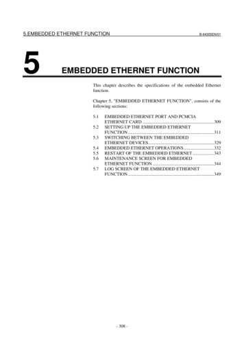
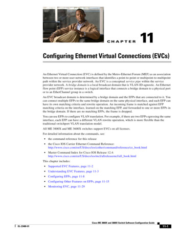
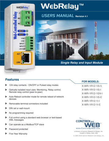
IntroductionWebRelay Users Manual1.5 Connectors & IndicatorsWebRelay has two removable terminal connectors and an Ethernet connector. The three-positionterminal connector is used to connect the relay to the load. The five-position terminal connector providespower to the internal web server, and has connections for the optically-isolated input and 5VDC output.RelayThe WebRelay has an internal high-current relay. Screw terminals are provided for the Common,Normally Open, and Normally Closed contacts of the relay. The screw terminals are internally connecteddirectly to the relay with no internal fuse or other over-current protection. The relay contacts are isolatedfrom all other circuits.Digital InputThe WebRelay has an optically-isolated digital input. The optically-isolated input provides electricalisolation between the digital input and the low voltage control circuits of the WebRelay.Power SupplyConnect a 9-28VDC source to the Vin and Vin- terminalsLED IndicatorsRelay: Green, Illuminated whenever the relay is energized. When the relay coil is energized,the NO (Normally Open) contact is closed and the NC (Normally Closed) contact is open. Theload device that is connected to the relay contacts may be on or off when the coil is energizeddepending on how its wired.Input: Green, Illuminated when a sufficient voltage is applied to the opto-coupler inputPage 10Link:Green, Power is on and WebRelay is properly connected to a networkAct:Amber, Flashes when network is activeXytronix Research & Design, Inc.
WebRelay Users ManualThe WebRelay has a five-position, removable screw terminal connector for power and input connections, thethree-position connector provides connections to the internal relay.5-Pin ConnectorTerminal DescriptionVin Power supply input (not required for POE model)Do not exceed maximum power supply voltage (9-28VDC)Vin-Power input- (GND)Negative side of the power supplyInput-Digital Input - The negative side of the optically-isolated input.Input Digital Input The positive side of the optically-isolated input. 5Vout 5VDC out. This voltage is provided as a convenient voltagesource for the optically-isolated input. It can be used, forexample, when a switch is needed to control the input state.This can be done by connecting the INPUT- directly to VINand then connecting the 5Vout to through a switch to theINPUT . Do not use this output for other purposes.3-Pin ConnectorTerminalDescriptionCRelay COMMONNORelay NORMALLY OPENNCRelay NORMALLY CLOSEDXytronix Research & Design, Inc.Page 11
IntroductionWebRelay Users Manual1.6 Accessing the WebRelay using a Web BrowserThe WebRelay has a built-in web server that provides the user simple web pages that can be accesseddirectly using a standard web browser. This allows users to access the unit with NO SPECIALSOFTWARE installed on their computer. This is ideal for applications that require a quick and simplesolution that does not need to be accessible to more than a few people. This configuration is simple tosetup, simple to use, and can be accessed from just about any computer or smart phone.Note: Network routers may need to be configured to allow access from computers outside of the localnetwork (see Appendix C: Accessing the WebRelay Over The Internet).Page 12Xytronix Research & Design, Inc.
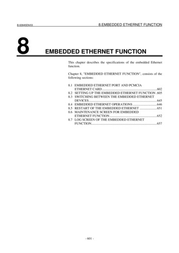
WebRelay Users ManualSection 2: Installation and ConnectionsInstallation consists of mounting the WebRelay, connecting it to an Ethernet network, providing power,and connecting the relay contacts to the device that will be controlled. Optionally, a control signal maybe connected to the optically-isolated input. The installation is completed by configuring the moduleusing a web browser.The WebRelay supports connection to 10Mbps and 100Mbps networks. Although 100Mbps networksare faster, the amount of data transferred to and from this device is very minimal and little if anyperformance increase will be gained by setting it to 100Mbps. There are advantages however, tooperate this device at 10Mbps. At 10Mbps, less power is required, the unit runs cooler, and the lifetimeof the device is extended.2.1 Installation Guidelines This unit must be installed by qualified personnel. This unit must not be installed in unprotected outdoor locations. This unit must not be used for medical, life saving purposes, or for any purpose where its failurecould cause serious injury or the loss of life. This unit must not be used in any way where its function or failure could cause significant loss orproperty damage. Do not use to directly control motors or other actuators not equipped with limit switches or othersafeguards to protect from equipment or wiring failures. The WebRelay should be located in a clean, dry location where it is protected from theelements. Ventilation is recommended for installations where ambient air temperatures areexpected to be high. See Appendix H: Mechanical Information for additional mechanical details. The WebRelay must installed inside an NRTL certified industrial control panel or similar NRTLcertified fire/electrical enclosure. If the WebRelay is used in a manner not specified by Xytronix, the protection provided by theequipment may be impaired.2.1.1 Wall MountingMount the WebRelay to a wall by using two #8 screws. Attach thescrews to the wall vertically spaced exactly 2.5 inches apart. Thehead of the screw should be about 1/10 inch away from the wall.Xytronix Research & Design, Inc.Page 13
Installation and ConnectionsWebRelay Users Manual2.1.2 DIN-Rail MountingThe WebRelay can be mounted to a standard (35mm by 7.55mm) DIN-Rail. Attach the WebRelay to theDIN-Rail by hooking the top hook on the back of the enclosure to the DIN-Rail and then snap the bottomhook into place. To remove the WebRelay from the DIN-Rail, use a flat-head screwdriver. Insert thescrew driver into the notch in the release tab and pry against the enclosure to release the bottom hook.Page 14Xytronix Research & Design, Inc.
WebRelay Users Manual2.2 Making ConnectionsCAUTION: Make sure the power is shut off before making connectionsCAUTION: This unit should be installed by a qualified technician.CAUTION: Miswiring or misconfiguration could cause permanent damage to the WebRelay, theequipment to which it is connected, or both.A removable terminal connector is provided for making the power connections. To help protect theWebRelay from mechanical stress, remove the terminal connector before making the connections.1. Make sure power is turned off.2. Remove the terminal connector from the WebRelay and make wiring connections to theterminals. This technique avoids stressing the internal components while torquing the screws.3. Reconnect the terminal connector.4. Apply power.It is recommended that any load (device to be controlled) not be connected until after the WebRelay hasbeen configured and tested. By doing this, wiring and configuration mistakes will not cause the loaddevice to turn on unexpectedly. Make certain the wires are properly inserted into to the terminals andthat the screws are tight.See Appendix D: Specifications for wire size, temperature rating and torque requirements for makingconnections to the terminal blocks.2.2.1 Power Supply ConnectionsThe WebRelay requires power for its internal logic circuits. Connect a 9-28 VDC power supply to the Vin and Vin- (Gnd) terminals. A regulated power supply is recommended, such as a wall-mount AC-DCadapter. Verify that the adapter is rated for the operating current of the WebRelay (See Appendix D:Specifications for the current requirements.) Multiple WebRelay units may be connected to a singlepower supply by connecting the power supply input terminals in parallel. The power supply must have ahigh enough current rating to power all units connected.The model X-WR-1R12-1I-E is normally powered from an 802.3af compliant Power Sourcing Equipment(PSE) device which passes DC power, along with data on the twisted-pair Ethernet cabling. This allowsa single cable to provide both the data connection and DC power. With the X-WR-1R12-1I-E noconnections are needed to the Vin and Vin- terminals. The Vin and Vin- terminals however, can beused as a backup power source. The WebRelay has an internal “diode or” circuit between the Vin terminal and the internal Powered Device (PD) circuits. If a power supply is connected to the Vin terminal, the WebRelay will draw power from the PSE if the input voltage is less than 12.0V, and fromthe Vin terminal if the input voltage is greater than 12.0V. If the PSE power fails, the WebRelay willdraw all power from the Vin terminal.Note: the X-WR-1R12-1I5-E power-over-ethernet module does not support 9-28VDC as a backup powersource on the Vin
Jul 08, 2010 · Relay Output The WebRelay has an internal high-current relay. Screw terminals are provided for the Common, Normally Open, and Normally Closed contacts of the relay. The screw terminals are internally connected directly to the relay with no internal fuse or other over-current protection. The rela