Transcription
Protective Relay BasicsPresented byAndrew Legro P.E.Nikita MishraABB Inc.
Speaker BioAndrew LegroLicensed professional engineer for 15 years. 25 years in the electrical industry including 10years as a MEP consulting engineer.Experienced in medium voltage and low voltage design and construction. Specialized inhealthcare and industrial facilities. Provided electrical power system consulting and studieswhile working for major electrical equipment manufacturers.Currently resides in Orlando, FL and provides application consulting for engineersthroughout the state. Proficient in all ABB/GE medium and low voltage distributionproducts. Also proficient in system modeling and studies with EasyPower and EMTP.Email: Andrew.Legro@us.abb.com
Speaker BioNikita MishraProduct Specialist (West Region) for Digital Substation Products at ABB Inc. since May2021. Currently residing in Denver, Colorado. Previous experience in designing low voltageand medium voltage switchgear, relay panels and custom control panels as an ElectricalEngineer at ESSMetron, Denver CO.Graduated with a Master of Science in Electrical Engineering from The University of Texasat Dallas in 2018 and with a Bachelor of Technology in Electrical and ElectronicsEngineering from VIT University, Vellore, TN, India in 2016.Email: nikita.mishra@us.abb.com
—Overview The objective of this presentation is to convey a basic understanding of protective relays to anaudience of engineers already familiar with low voltage protective device coordination. Fundamental concepts and terminology will be taught using the electromechanical overcurrent relay asa foundation and then these concepts will be expanded to modern numerical relays.Slide 4
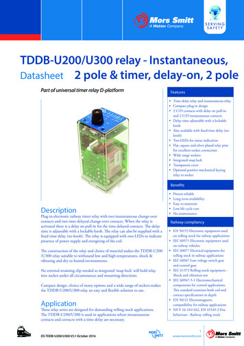
—IntroductionRelay Vs Low Voltage Circuit BreakerRelayLow Voltage Circuit Breaker ABB Numerical RelayType REF-615January 27, 2022Slide 5Medium & High Voltage Protection ( 1000VAC ) Low Voltage Protection ( 600VAC) All-in-one solution. Combines protection,sensors, control power, and circuit breakerin a single package Single component in a larger assembly.Provides protection, logic, and metering Requires current transformers, controlpower, and the circuit breaker itself Uses thermal, electromagnetic, andhydraulic elements (historically) Uses induction and electromagneticelements (historically) Simplified application engineering Lower accuracy (historically) Complex application engineering Higher Accuracy (historically)ABB LV Circuit BreakerTmax XT7
—Relay vs Low Voltage Circuit BreakerSymbols and TerminologyRelayLow Voltage Circuit Breaker Individual symbols for each element Single symbol ANSI / IEEE device numbers to define protective functions Defined by trip type: Thermal Magnetic, Electronic, LSI Tap, Time Dial, Range, Curve Type, Inverse(ness) of Curve, CT Ratio Frame Size (amps), Sensor Rating (amps), Trip Rating Pickup, Delay, Long Time, Short Time, Instantaneous, GroundJanuary 27, 2022Slide 6
—ANSI / IEEE Electrical Power System Device NumbersCommonly used devices per IEEE Std C37.2 - 2008DeviceNumberFunction27Undervoltage Relay37Undercurrent RelayAlso used for underpower46Phase Balance Current RelayAlso used for reverse phase47Phase Balance Voltage RelayAlso used for phase sequence49Thermal RelayMotor (49M), Generator (49G), Transformer (49T)50Instantaneous Overcurrent RelayPhase (50P), Neutral (50N), Ground (50G)51AC Time Overcurrent RelayPhase (51P), Neutral (51N), Ground (51G)52AC Circuit BreakerType not specified, can be air, oil, vacuum, or SF659Overvoltage Relay81Frequency Relay86Lockout RelayTypically added to a breaker close circuit to prevent accidental reclosure after a trip.87Differential Protective RelayBus (87B) or Transformer (87T)January 27, 2022Slide 7Notes
—ANSI / IEEE Electrical Power System Device NumbersCommonly used device number suffixesSuffixDefinitionExamplePPhase51P (Phase Time Overcurrent)NNeutral51N (Neutral Time Overcurrent)GGround51N (Ground Time Overcurrent)BBus87D (Bus Differential)TTransformer87T (Transformer Differential)BFBreaker Failure50BF (Breaker Failure, zero or short time delay)January 27, 2022Slide 8
—Principle ComponentsThree fundamental components required for each circuit breaker.Protective RelayJanuary 27, 2022Slide 9CurrentTransformerCircuit Breaker
—Principle ComponentsSchematic SymbolsCTCircuitBreakerJanuary 27, 2022Slide 10ProtectiveRelay
—Principle ComponentsComponents as integrated into switchgearComponents for each breakerABB Advance MV Metal Clad SwitchgearJanuary 27, 2022Slide 11
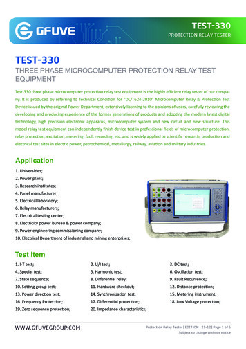
—Current Transformer “CT”Basic Concepts CT’s transform line current down to a signal level that is acceptable to the relay. This signal level istypically 5A nominal. Primary side is the line current and secondary side is connected to the relay. Multiple relays can use the same CT. The limit is defined by the electrical load (burden) of the relaysin relation to the maximum terminal voltage. Ratios are stated as “X” primary current to 5A i.e., 600:5 means that 600A of line current produces5A of secondary current. There are two basic classes of current transformers: metering and relaying. Metering class relaysshould not be used for relay applications however relaying class CT’s can be used for metering whenhigh accuracy is not required. For a protection engineer, the most important CT characteristics are: Ratio Accuracy ClassABB Type SAB Current Transformer
—Current Transformer “CT”What the protection engineer needs to know Ratio Typically, 5A secondary although 1A secondary is available. Can be single or multi ratio (MR). Rule of thumb, select a ratio slightly larger than the rating of thecircuit to be protected. Numerical relays have more forgiveness than induction disk. Accuracy Class Class C is the most common. The number after the letter designates approximately how muchvoltage can be developed across the CT secondary prior to saturation.Larger numbers correspond to more core steel (more power output)for a given CT ratio. Accuracy class is less critical to numerical relays due to their inherentlylow burden. Saturation Curve (optional) Supplemental to accuracy class. Can be very critical in specific relay applications such as differential. Less critical for low burden relays where the short circuit ratio is lessthan 20.IEEE Relaying ClassC 100Terminal Voltage10 – 20 – 50 – 100 – 200 - 400 – 800Accuracy ClassC or T C class is considered a low leakage design and errors may beCalculated from excitation curve. T class are high leakage and must be verified by Test.
—Medium and High Voltage Circuit BreakerBasic Concepts Generally, MV and HV circuit breakers do not contain relays, trip units, or any element that willautomatically cause the breaker to operate. They require relays and sensors to complete the system. Virtually any manufacturer / model relay can be used with any manufacturer / model circuit breaker.It is the responsibility of the application engineer to ensure that the relay and circuit breakercorrectly specified and integrated. Interrupting technology can vary considerably and includes air, oil, vacuum or gas (SF6). Style can vary considerably and includes air-insulated metal clad switchgear, air-insulated metalenclosed switchgear, solid dielectric, gas insulated switchgear, dead tank outdoor, live tank outdoor,pad mount, pole mount. Relays can also be applied to non-beaker applications such as load interrupting switches both fusedand non-fused.ABB ADVAC 15kV Vacuum Breaker
—Medium and High Voltage Circuit BreakerWhat the protection engineer needs to know Frame size For 15kV switchgear this is typically 600A, 1200A, 2000A, 3000A Interrupting rating in kA symmetrical RMS Typical values @15kV are 25kA, 31.5kA, 40kA, 50kA, 63kA Interrupting time Typical 3 or 5 cycles @60hz Short time withstand Typically, 2 seconds for ANSI switchgear Various Ratio and class of current transformers available Trip coil voltage DC – 24V, 48V, 125V, 250V AC – 120V, 240V (needs capacitor trip) Note trip coil voltage and circuit breaker control voltage may not be the same Control schematicABB ADVAC 15kV Vacuum Breaker
—Overcurrent RelayBasic Concepts There are many types of protective relay functions, but this presentation will focus on the mostcommon type, basic overcurrent device 50/51 (instantaneous and time overcurrent). Traditionally, protective relays were electromechanical devices utilizing induction disk, coils,contacts, and solenoid elements to determine protective characteristics. Traditional overcurrent relays (50/51) used an induction disk for the time delayed element (51) anda solenoid for the instantaneous element (50). Modern multifunction relays combine basic overcurrent protection with many additional relayelements into a single compact unit.ABB Numerical RelayType REF-615
—Overcurrent RelayElectromechanical Type Traditionally, protective relays were electromechanical devices that utilized induction disk, coils,contacts, and solenoid elements to determine protective characteristics. Electromechanical relays: Very accurate relative to the simpler trip units used in early low voltage circuit breakers. Low sensitivity to changes in ambient temperature Allowed for advanced protective functions by virtue of their inherent ability to sum voltageand current phasors. Very reliable when properly maintained and tested. Fundamental technology used from the beginning of the 20th century until the 1990’s Required complex wiring and multiple devices for each breaker. A typical 3 phase breaker wouldrequire a minimum of 3 relays, one for each phase. Each protective function typically required itsown discrete relay. Largely replaced by multifunction numerical relays. Many remain in service and are also used in new systems as backup to numerical relays.ABB Induction DiskOvercurrent RelayType CO-9
—Electromechanical RelayPhysical and form factorABB Electromechanical Relay – Type CO-9January 27, 2022Slide 18ABB Numerical Relay – Type REF-615
—Electromechanical RelayDraw-out element in protective caseType CO-9 in standard caseJanuary 27, 2022Slide 19Internal draw-out element
—Induction DiskPrinciple of operation Induction disks are used for time delayed elements. Moving contact connected to a rotating aluminum disk. Alternating current is induced into the disk causing it to rotate relative totwo stationary but phase shifted magnetic fields. In a standard overcurrent relay, the phase shifted fields are created by ashaded pole structure. Restraining torque is created by a permanent magnet. Return torque iscreated by a spiral spring. Time Dial – Sets the starting distance between the moving and stationarycontact. This determines the elapsed time to trip for a given current. Tap – Sets the current (field strength) in the main coil proportional to agiven current.January 27, 2022Slide 20
—Induction DiskPrinciple of operation Accurate but very delicate mechanism. Not reliable in harsh atmospheres. Disk overtravel needs to be accounted for in coordination studies. The setting methods (particularly the time dial) are imprecise. Standardoperating procedure was to set, test, adjust settings, retest, repeat.January 27, 2022Slide 21
—Type CO Overcurrent RelayTime Overcurrent Unit Settings51 Tap Adjustment51 Time DialJanuary 27, 2022Slide 22
—Type CO Overcurrent RelayInstantaneous Trip – IIT Unit Settings50 Range Tap50 Pickup Adj50 Trip FlagJanuary 27, 2022Slide 23
—Type CO Overcurrent RelayTime Overcurrent – ICS Unit. Provides seal-in around the induction disk contacts and Trip Flag (a.k.a indicating target)51 Trip FlagJanuary 27, 2022Slide 24
—Example Relay Installation in SwitchgearMinimum of 3 to 4 electromechanical relays per breakerExample schematic – 3 phase plus groundJanuary 27, 2022Slide 25
—50/51 Time Current Curve51 – Time Overcurrent Curve Electromechanical: The curve is fixed and designated by relay model(i.e. CO-11 Very Inverse, CO-9 Very Inverse) Numerical: Configurable to standard relay types Tap Increasing tap values move the curve to the right. Standard convention is tap setting is equal to the CT secondarycurrent that will cause the relay to pickup**. (i.e. 200:5 CT with atap setting of 3 will pickup at 120A line current) Electromechanical: Ranges are by specific relay model, typically 6taps available. (i.e. range 2.0 to 6.6 with taps at 2.0, 2.5, 3.0, 3.5,4.0, 5.0, 6.0) Numerical: 0.25 to 25 in 0.05 steps for 5A secondary (0.05 to 5 timesCT secondary current). Time Dial Increasing time dial moves the curve up. Electromechanical: 0.5 to 11 Numerical: 0.05 to 15 in 0.01 stepsJanuary 27, 2022Slide 26Increasing Time DialFundamental settings & how they affect the curveIncreasing Tap5150Increasing Pickup
—50/51 Time Current Curve50 – Instantaneous Overcurrent Pickup Increasing pickup moves the curve to the right. Standard convention is tap setting is equal to the CT secondarycurrent that will cause the relay to pickup**. (i.e. 200:5 CT with aninstantaneous setting of 40 will pickup at 1600A line current) Electromechanical: Ranges are set by tap plug. Typically, 3 rangesavailable such as 2-7, 7-14, 14-48. Adjustment screw then sets thespecific tap within the range. Numerical: 0.5 to 200 in 0.05 steps for 5A secondary (0.1x to 40xtimes CT secondary current).Increasing Time DialFundamental settings & how they affect the curve** Include note numerical relays, CT multiplier and the effect on settings tablein Easypower.Slide 275150Increasing PickupJanuary 27, 2022Increasing Tap
—50/50TD/51 Time Current CurveNumerical Relay with delayed device 50 (50TD)50TD – Delayed Instantaneous Overcurrent Numerical Relays Only Pickup Increasing pickup moves the curve to the right. Numerical: 0.5 to 200 in 0.05 steps for 5A secondary (0.1x to 40xtimes CT secondary current).Delay Increasing pickup move the curve to the right. Numerical: 40ms to 200s in 10ms steps.50TDIncreasing PickupIncreasing Delay 51January 27, 2022Slide 2850
—Inverse Time Curve FamilyABB CO RelayTypeCurve NameTypical ApplicationsCO-11Extremely Inverse Cable protectionTransformer protectionFuse coordinationLV Breaker coordinationCO-9Very Inverse Motor protectionSimilar applications to CO-11CO-8Inverse Coordination with legacy and special devicesBackup protectionCO-7Moderately InverseCO-6Definite Time Delayed instantaneous (50TD).Other protective functions where simpletime delay is required such as overvoltage.CO-5Long Legacy device – similar applications to CO-11or CO-9 or motors with long starting timesCO-2Short Legacy device – similar applications to CO-6January 27, 2022Slide 29Equal tap and time dialsettings
—Definite Time CurveABB CO-6 Relay vs Ideal Definite Time The ideal definite time relay has binary response. It only operates (trip)when the current has exceeded the pickup level and the timer has reachedlimit. Current in excess of the pickup value does not affect the idealresponse. The electromechanical implementation of definite time is far from idealresponse. It’s essentially an inverse time device with slight inversecharacteristics.January 27, 2022Slide 30
—Device 51-Time DialCO-9 Very Inverse Time Dial Range 0.5 to 11 Example of how the time dial adjustments change the response of relay. The curve is not only shifts up and down (time) but also slightly left andright (amps).January 27, 2022Slide 31
—Coordination IntervalsTotal time to trip and clear Relay curves show only the time for the relay itself to operate and do notinclude additional time required to trip and clear the fault. The relay curveis shown as the dark blue line. Additional time must be added to the curve when coordinating to otherprotective devices. This additional time is shown in the light blue area. In addition to the relay curve, the following items must be accounted for tocompute the total maximum time to trip and clear: CT Accuracy - time varies but 12 cycles is a good safety factor barringdetailed analysis. Circuit Breaker Trip and Clear Time – 3 or 5 cycles Interposing relay delays – 1 to 3 cycles Relay Overtravel (Electromechanical Only) – Assume 6 cycles barringavailability of detailed information. Barring detailed information and analysis, recommended coordinationintervals are: 12 cycles (0.2 sec) for numerical relays 24 cycles (0.4 sec) for electromechanical relaysJanuary 27, 2022Slide 32Total trip and clear timewith overtravelRelay Only Curve
—Relay to Relay CoordinationElectromechanical Type Relay The fault needs to be completely clearedbefore the upstream relay picks up (redcurve) Electromechanical - Minimum timecoordination interval between relays is 0.4seconds (24 cycles). The spacing between numerical relays can bemuch shorter typically 0.3 seconds (12 cycles)but no less then 0.1 seconds (6 cycles).January 27, 2022Slide 330.4 Sec Min
—Transformer ProtectionElectromechanical Type Relay This is an example of typical utility upstreamtransformer and feeder protection coordinatedwith a low voltage service main circuit breaker. Coordination between the customer and utility isoften overlooked. The transformer’s primary fuse (red curve) andthe low voltage main (purple curve) do not haveto coordinate as they are in series. Setting the low voltage main below the fuse canprevent unnecessary utility service calls.January 27, 2022Slide 34
—Transformer ProtectionNumerical Type Relay – ABB REF-615 This curve illustrates enhanced protection madepossible by numerical relays. Coordination intervals can be cut in half. Adding the 50TD element to both relays reduces thefault clearing time while maintaining full selectivity. High precision settings allow the primary side relay tobetter protect the full damage curve of the transformer(both three phase and unbalanced damage curves).January 27, 2022Slide 35
—Recommendations For Relay CoordinationRules of thumb to be used only with engineering judgement.1.For electromechanical relays: Avoid mixing different manufacturers and models of overcurrent relay in the same circuit. Curve names were notstandardized across manufacturers. For example, an ABB CO-9 Very Inverse relay does not have the same curve as a GE IAC 53 Very Inverse curve.2.For numerical relays: Mixing manufacturers is typically not an issue. Numerical relays offer a large selection of curve types. When possible, choose ANSIstandard curves (applies to North America only).3.The upstream relay should use an equal or less inverse curve type then the downstream relay. For example, an upstream Very Inverse relay will coordinatewith a downstream Extremely Inverse, but an upstream Extremely Inverse relay will not (necessarily) coordinate with a downstream Very Inverse relay.4.When coordinating with expulsion type fuses (non-current limiting) use delayed instantaneous trip (50TD) to maintain full selectivity.5.When coordinating with current limiting type fuses, set the instantaneous trip (50) to 1.1x the current limiting value of the fuse.January 27, 2022Slide 36
—EasyPower ExamplesNumerical Multifunction Relay – Specifications TabJanuary 27, 2022Slide 37
—EasyPower ExamplesNumerical Multifunction Relay – Settings TabJanuary 27, 2022Slide 38
—Numerical RelayMultiple protection elements in a single deviceBasic Feeder Protection – Current OnlyJanuary 27, 2022Slide 39Advanced Feeder Protection – Current and Voltage
—Numerical RelayREF-615 Device 51 Trip Curves AvailableJanuary 27, 2022Slide 40
Thank us.abb.com
51 AC Time Overcurrent Relay Phase (51P), Neutral (51N), Ground (51G) 52 AC Circuit Breaker Type not specified, can be air, oil, vacuum, or SF6 59 Overvoltage Relay 81 Frequency Relay 86 Lockout Relay Typically added to a breaker close circuit to prevent accidental reclosure after a trip. 87 Differential Protective Relay Bus (87B) or .