Transcription
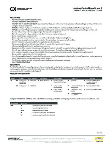
Lighting Control Panel 4 and 8INSTALLATION INSTRUCTIONSPRECAUTIONS READ AND FOLLOW ALL SAFETY INSTRUCTIONS. CAUTION: USE COPPER CONDUCTOR ONLY CAUTION: RISK OF ELECTRICAL SHOCK. To prevent electrical shock, turn off power at the circuit breaker before installing or servicing unit. Never wireenergized electrical components NOTE: For installation by licensed electrician in accordance with the National and/or Electrical Codes and the following instructions NOTE: Do not install if the product appears to be damaged. Be sure to read and understand all instructions before installing or servicing unit Run low voltage wiring with line voltage wiring in their respective compartments For indoor use only. Do not use outdoors unless all environmental requirements are met Do not mount near gas or electric heater Disconnect switch or a circuit breaker must be provided and marked as the disconnecting device The use of accessory equipment not recommended by the manufacturer may cause an unsafe condition Confirm that device ratings are suitable for the application prior to installation No user serviceable parts contained inside unit. Refer all service related questions to the factory All servicing shall be performed by qualified service personnel Equipment should be mounted in locations and at heights where it will not readily be subjected to tampering by unauthorized personnel Use only approved materials and components (i.e. twist on connectors, electrical box, etc.) as appropriate for installation If the equipment is used in a manner not specified by the manufacturer, the protection provided by the equipment may be impaired Do not use this equipment for other than intended use If any Emergency Circuits are fed or controlled from this panel, it must be located electrically where fed from a UPS, generator, or other guaranteedsource of power during emergency and power outage situations The CX panel enclosure and door are a complete assembly. Doors are not purchased separately SAVE THESE INSTRUCTIONS!DESCRIPTIONThe CX Lighting Control Panels are lighting control systems designed to control lighting loads as well as motor loads up to 2 HP. The system includes anenclosure, power supply and or transformer, motherboard with Class 2 I/O user interface, and relay cards to control loads. The relay card is an open-typeaccessory intended for installation inside the panel.PRODUCT CONFIGURATIONMODELCXSPACESINPUT VOLTAGE044 relay spaces(Stand Aloneversion only)2120/277VAC088 relay spaces3120/347VACENCLOSURESNEMA 1 EnclosureRELAY QUANTITYRELAY TYPEOPTIONS00No relays included(Required SP Relay Type)SPSpace OnlyNStand-alone (4 Relay Panelis neither a Master orSecondary Panel044 relays installed(fully populated)2N1-Pole elect. held N.O.relays (CXR2N)MMaster (available in CX08)088 relays installed(fully populated)3N1-Pole latching relays(CXR3L)SSecondary (available in CX08)TN2-Pole elect. held N.O.relays (CXRTN)Examples: CX082S083LM - CX8 Relay Panel, 120-277VAC universal input, with 8 30A latching relays installed in NEMA 1 surface mount Master panelRELAY MODELRELAY TYPECXR2N1-Pole, Electrically Held, N.O.,120/277VAC3L1-Pole, Latching,120/277/347VAC3LEM*1-Pole, Latching,120/277/347VACTN2-Pole, Electrically Held, N.O., 208/240/480VACTC*2-Pole, Electrically Held, N.C., 208/240/480VAC72-00445D701 Millennium Blvd. Greenville, SC 29607 (864) 678-1000 (866) 898-0131 - fax www.hubbellcontrolsolutions.comCopyright 2019 Hubbell Control Solutions, a division of Hubbell Lighting, Inc. All rights reserved. All product and company names, logos and productidentifiers are trademarks or registered trademarks of Hubbell Lighting, Inc. or their respective owners. Use of them does not necessarily imply anyaffiliation with or endorsement by such respective owners.3300B 051619
Lighting Control Panel 4 and 8INSTALLATION INSTRUCTIONSPANEL NOTES CX Panels are manufactured fully populated with relays or empty without relays. Relays to be purchased separately and to be installed in the field bya certified electrician. Relays are mounted with lighting circuit terminals in the high voltage area. The low voltage control inputs are in the low voltage area of the panel. 2-Pole relays take the same amount of space as 1-Pole relays. Panels ordered fully populated are pre-installed with the same relay type as listed in the ordering chart. Relay Type CXR3LEM* and CXRTC* are notavailable in fully populate panels and must be ordered separately to be installed in the field. “00” option has no relays; any purchase relays must be installed in the field. Secondary panels have a pre-installed Secondary Interface Card and separately packaged Master Interface Card. Join panels with a Cat5e/6 cable,T568B wiring scheme (Not to exceed 750') The following information describes the CX 04 and 08 relay panel installation. For programming information, refer to the “CX Panel Quick Start Guide”provided as a separate document with the Panel. All CX panels come with 2 door lock keys, taped to the interiorNOTE: CX04 Relay panel is Stand Alone only. Does not function with Master/Satellite Interface cards.Figure 172-00445D701 Millennium Blvd. Greenville, SC 29607 (864) 678-1000 (866) 898-0131 - fax www.hubbellcontrolsolutions.comCopyright 2019 Hubbell Control Solutions, a division of Hubbell Lighting, Inc. All rights reserved. All product and company names, logos and productidentifiers are trademarks or registered trademarks of Hubbell Lighting, Inc. or their respective owners. Use of them does not necessarily imply anyaffiliation with or endorsement by such respective owners.3300B 051619
Lighting Control Panel 4 and 8INSTALLATION INSTRUCTIONSCX LIGHTING CONTROL PANEL DIP SWITCHESCX Panel Motherboards are differentiated by dip switches located on the physical motherboard. By default, the dip switches for the CX panel motherboardsshould be configured in the factory, however it may be necessary to confirm the dip switches based on lack of communication or replacement ofmotherboards.(CX04 Panels do not have a dipswitch since they are always stand-alone). The CX motherboard dip switches are located on bottom left location of a CX08 Panel motherboard. Secondary CX panels do not have a CX Master Controller connected. CX04 Panels do not have a dipswitch and are always a stand-alone panel. The CX04 cannot be converted to a Master or a Secondary PanelINSTALLATION PREPARATIONPrior to installation of the CX panel, review this manual, review site drawings, verify a relay schedule has been provided prior to installation, onsite contactto confirm functionality, associated diagrams and electrical bill of material. A CX Panel is never to be energized during installation or replacement of anycomponents.ENCLOSURE MOUNTINGMaterials CX Panel (14.5” W x 17.0” H x 4” D) Construction Level 3 - Minimum, #12 mounting screws, length and anchor support material capable of supporting the weight of a CX panel and associated cabling. #2 x 4” Phillips head screw driver for CX Relay Line voltage terminals and CX Relay mounting screws 2.5mm x 50mm Precision flat head screw driver for low voltage input terminations Wire Stripper/Cutter appropriate for low voltage and line voltage applicationsTypically, a CX panel is installed near the circuit breaker panel or in the ceiling of the room containing the lighting circuits to be controlled. Select anappropriate location that meets the environmental conditions listed in the specification section of this document. The panel interior is divided into highvoltage and low voltage areas as shown in Figure 1 on page 2. Select an appropriate location for incoming line voltage panel power, branch circuits to becontrolled and low voltage input wiring. Top and bottom part of the enclosure provided each with 7 conduit openings and knockouts. Knockouts are min. 1.5 mm thick. It is not necessary to locate all the branch circuit neutral cables into the CX Line Voltage gutter(s). Doing so may result in cramp space to work in andincreased complexity when servicing the panel in the future. All terminations within the panel enclosure require installation by a licensed electrician in accordance with National and/or local Electrical Codes. If mounting a CX08 relay panel it will be necessary to remove the bottom two (2) relays located on the bottom of the motherboard prior to markingor attaching mounting screws (See next section).CX08 RELAY REMOVAL FOR PANEL MOUNTING (Fully populated version)Using a Philips head screw driver remove the bottom 2 relay mounting screws (shown below) holding those relays to the mounting rails. Gently pull andseparate the relay from the motherboard’s relay plug connector staying under the metal barrier.Figure 2701 Millennium Blvd. Greenville, SC 29607 (864) 678-1000 (866) 898-0131 - fax www.hubbellcontrolsolutions.comCopyright 2019 Hubbell Control Solutions, a division of Hubbell Lighting, Inc. All rights reserved. All product and company names, logos and productidentifiers are trademarks or registered trademarks of Hubbell Lighting, Inc. or their respective owners. Use of them does not necessarily imply anyaffiliation with or endorsement by such respective owners.72-00445D3300B 051619
Lighting Control Panel 4 and 8INSTALLATION INSTRUCTIONS1. Locate the enclosure on the mounting surface and use a level to ensure that it is properly oriented and aligned.2. Secure the enclosure to the mounting surface with hardware as appropriate for the application using the three keyed mounting holes located nearthe top corners and bottom center of the enclosure as shown in the Figure 3. The location of the mounting holes is the same for a CX 04 and CX 08relay panel.CX08 Relay Panel; After the panel is mounted and secured, reconnect the 2 CX relays temporarily removed during the installation process. Navigate the relay card under the metal barrier Align the pins of the relay card and the relay plug connector and press into the motherboard connector. Secure with the relay mounting screw. Verify the pins aligned correctly.Once the CX panel is mounted and for the CX08 relays are reattached, remove any debris caused by installation. It may be necessary to remove the doorfor mounting. (See next section)Figure 3CX08 Relay Panel Shown Bottom Relays Removed for Installation72-00445D701 Millennium Blvd. Greenville, SC 29607 (864) 678-1000 (866) 898-0131 - fax www.hubbellcontrolsolutions.comCopyright 2019 Hubbell Control Solutions, a division of Hubbell Lighting, Inc. All rights reserved. All product and company names, logos and productidentifiers are trademarks or registered trademarks of Hubbell Lighting, Inc. or their respective owners. Use of them does not necessarily imply anyaffiliation with or endorsement by such respective owners.3300B 051619
Lighting Control Panel 4 and 8INSTALLATION INSTRUCTIONSCX DOOR REMOVALIt may be necessary to remove the door for ease of installation. (see Figure 4)1.2.3.4.In all instances the CX door is to be removed, verify the panel is not energized.Disconnect the CX Controller ribbon cable from the CX controller ribbon connector by simply pulling the end piece off the mother board.Opening the door slowly you will see the location in the hinge where the door can be lifted to detach the door from the enclosure.Once lifted place the door in a safe place to ensure the controller is not damaged by field work.ATTACHING THE CX DOOR1.2.3.4.In all instances the CX door is to be removed, verify the panel is not energized.Align the door hinge and the enclosure, slide and rotate the door to slide into the hinge slot.Connect the CX Controller Ribbon Cable into the CX Controller Ribbon Connector.The end connector of the ribbon cable is slotted and should not be forced into place.CONNECTING PANEL POWERThe panel is designed to operate on 120/277 VC for input voltage "2" designator, or 120/347VAC for input "3" designator. Panel input power is suppliedto the power supply located in the upper right of the panel as shown in Figure below. The output power to the CX Motherboard is in the upper centerchannel of the panel. With the power turned off, route the dedicated panel power supply leads to the transformer and connect them to the appropriatesystem voltage specific leads. Connect the power supply ground lead to the panel chassis grounding lug. A label indicating this ground lug is locatedadjacent to the connection location.72-00445D701 Millennium Blvd. Greenville, SC 29607 (864) 678-1000 (866) 898-0131 - fax www.hubbellcontrolsolutions.comCopyright 2019 Hubbell Control Solutions, a division of Hubbell Lighting, Inc. All rights reserved. All product and company names, logos and productidentifiers are trademarks or registered trademarks of Hubbell Lighting, Inc. or their respective owners. Use of them does not necessarily imply anyaffiliation with or endorsement by such respective owners.3300B 051619
Lighting Control Panel 4 and 8INSTALLATION INSTRUCTIONSThe connections from supply power to the panel power supply, is depicted on the Input Control Power Supply.NOTE: If validation of the transformer output is required; the voltage output should be 24VDC and can be tested from the low voltage secondary leadsconnected to the low voltage control input plug.NOTE: If the panel will be controlling emergency circuits, the panel power supply feed must be connected from uncontrolled normal power.CAUTION: When power is applied to the transformer, the unused transformer leads become electrified. Cap unused transformer leads with wire nuts toprevent electrical shorting.CAUTION: Panel supply power must be de-energized during installation and servicing of the CX panel.CONNECTING LIGHTING LOADSWith the power turned off, route the lighting system line and load leads through the high voltage area of the panel shown in Figure 1 on page 2. Connectline and load leads for each lighting load to the output terminals of the appropriate relay as delineated in the project plans and/or Panel Load Schedule.There are no Neutral connections to be made on the physical CX relays.CAUTION: Prior to making any connections to the relay outputs, verify that none of the loads are shorted. Failure to do so may result in personnel injury,damage to the panel, and void its warrantyNOTE: If no Panel Load Schedule exists, use the Panel Load Schedule Form supplied in the clear plastic pocket inside the Panel Door to record the lightingcircuit relay assignments while connecting the relays.NOTE: The panel is shipped with relays installed and electrically connected at their input control side. If, however, relays must be installed, reference theapplicable Relay Installation Instructions supplied with the individual Relay Cards on how to install relays.RELAY CONNECTION DIAGRAMSCONNECTING LOW VOLTAGE INPUTSBring the low voltage wiring for the contact inputs in through the knockouts in the low voltage wiring area where indicated on Page 2. Below are typicalconnections for singular devices. Wire size 14, 16, 18, 20, 22 AWG Recommended Tightening Torque: 0.45 N-m (4 in-lbs.) Inputs are software configurable through programming to support momentary switches, maintained switches (latching), motion sensors, or photosensors. Each Relay Card includes one low voltage input. These inputs may be connected prior to programming. Each mother board includes 2 Auxiliary Inputs and 1 output with N.C. and N.O. dry contacts. These inputs may be connected prior to programming. Input devices may be connected to any terminal location regardless of final control programming. Connect contact closure input devices to the inputterminals using recommended 18 AWG wire. All relay inputs located on a relay card can control the relay they are affixed as a momentary N.O. contact. This programming is not seen in the CXController programming and is a default function. Auxiliary inputs do not, by default, control anything. Auxiliary inputs are to be programmed through the controller for functionality.NOTE: Use the Panel Load Schedule Form supplied in the clear plastic pocket inside the Panel Door to record the low voltage input types whilemaking connections.72-00445D701 Millennium Blvd. Greenville, SC 29607 (864) 678-1000 (866) 898-0131 - fax www.hubbellcontrolsolutions.comCopyright 2019 Hubbell Control Solutions, a division of Hubbell Lighting, Inc. All rights reserved. All product and company names, logos and productidentifiers are trademarks or registered trademarks of Hubbell Lighting, Inc. or their respective owners. Use of them does not necessarily imply anyaffiliation with or endorsement by such respective owners.3300B 051619
Lighting Control Panel 4 and 8INSTALLATION INSTRUCTIONSNOTE: Most input connected devices can be located up to 500 feet away from the panel. Exact distances are based on quantity of devices, mixture ofdevices connected as well as the gauge of the wire used.NOTE: In some instances it may be necessary to use an auxiliary power supply to power occupancy sensors due to more sensors required than the panelcan energize. In these instances it is required to use an -RP occupancy sensor from HCS and use the dry contacts to activate the relays. Do not mix powerfrom the power pack and the panel voltage. (see HCS catalog of CX wiring diagrams for details)NOTE: The CX04/08 relays panels are to power up to 8 input powered devices. (Occupancy Sensors, Daylight Sensors, Wall Stations wit pilot lights)CX CONTROLLERA CX Controller is required to program and operate the CX Lighting Control Panel. There is to be only one CX Controller for any singular or Master/Secondary configuration. All Master CX Panels are pre-installed with a CX Controller. No Secondary CX Panels come with a CX Controller. The supplypower must be de-energized when removing or adding a CX Controller to a CX panel.Battery back up for the time clock is located in the back of the CX Controller. Disconnect power to the CX Panel, remove Controller stand-offs with a Phillipshead screw driver and detach the controller. The battery is visible and reachable when detached from the CX Door. Then reassemble after replaced.NOTE: It is possible to convert the Master panel to a Secondary panel, however dip switch settings must be updated to reflect the function change of theCX panel, see CX08 Motherboard description on page 3. It will be needed to remove the CX Controller from the panel. The ribbon cable is keyed and onthe connection to the motherboard pin number #1 in downward facing on the vertical connector.72-00445D701 Millennium Blvd. Greenville, SC 29607 (864) 678-1000 (866) 898-0131 - fax www.hubbellcontrolsolutions.comCopyright 2019 Hubbell Control Solutions, a division of Hubbell Lighting, Inc. All rights reserved. All product and company names, logos and productidentifiers are trademarks or registered trademarks of Hubbell Lighting, Inc. or their respective owners. Use of them does not necessarily imply anyaffiliation with or endorsement by such respective owners.3300B 051619
Lighting Control Panel 4 and 8INSTALLATION INSTRUCTIONSLCD Display: The display is to provide an interface to visual programming. It shows time and can be used for troubleshooting. See Programming guidefor functional instructions.SD Card Slot: When inserted, the CX Panel provides logging of events automatically. The text file is downloadable onto a PC to be reviewed duringtroubleshooting or validating programming. Logging shows, time stamps, and control events.Programming can also be loaded from another panel or to another panel to perform the same exact function and share the exact same configuration.Programming can be completed using the CX Configurator software located on the Hubbell controls website: CX Config V 2.07 n/tools). This software enables remote programming to be created, copied onto an SD card and then loaded onto the CXController. To create remote programming, it is required that the panel loads match the programming of the CX Configuration or the panel will notfunction as desired.Function Keys: The Function Keys are used for added functions shown above them on the display, for example; Edit, Save etc. These functions are definedin the user guide.Alphanumeric Keypad: The keypad is to make selections, add/change names in the programming. An additional function is the ESC to go back duringprogramming. The HELP button is used to view, on a popup, additional information to better define highlighted items on the screen that are defined thatmay need more description.Directional Keypad: The keypad is used to navigate through the menu selection of the CX Programming. The center ENTER button is used to confirmthe selection.CX DIMMING INTERFACE CARDThe dimming interface card is to provide 8, 0-10V dimming control by syncing the 0-10V current provided by the dimming driver of the fixture. Eachchannel on the dimming card can sync up to 30mA per channel. The only wall stations approved to connect to the RJ45 connectors are the CXSWwall stations. No more than 4 dimming cards can be used with any Master/Secondary configuration. Each Motherboard is designed to accommodate1 dimming card. For additional information see Install guide for the CXDIMCONTRBD. Only one CX Dimming Interface card can be used with a CX04 orCX08 panel.72-00445D701 Millennium Blvd. Greenville, SC 29607 (864) 678-1000 (866) 898-0131 - fax www.hubbellcontrolsolutions.comCopyright 2019 Hubbell Control Solutions, a division of Hubbell Lighting, Inc. All rights reserved. All product and company names, logos and productidentifiers are trademarks or registered trademarks of Hubbell Lighting, Inc. or their respective owners. Use of them does not necessarily imply anyaffiliation with or endorsement by such respective owners.3300B 051619
Lighting Control Panel 4 and 8INSTALLATION INSTRUCTIONSMASTER/SECONDARY INTERFACE CARDThe Master/Secondary cards are used to join 2 CX Lighting Control panels. Only two panels can be joined in this method. One must be a Master paneland the second must be a Secondary panel. These two panels should not be further than 700 feet apart. Standard Cat5e/6 cable is to be used in a T568Bconfiguration using standard RJ45 connectors.The Master or Secondary cards are to mount either on a Motherboard or stacked on top of a CX Dimming card that is seated on a motherboard. The Optionboard connectors are keyed. Please see Master/Secondary Interface instructions for more detail. A CX04 is not compatible with a CX Master or Secondarycard.OPERATING PANELThe User Interface control ribbon cable is supplied connected between the User Interface Ribbon Cable Connector on the Mother Board and the UserInterface Module that is attached to the panel door.The red indicator in the cable should align with the Pin 1 designation. The green ground jumper is supplied connected between the panel door and thepanel housing ground lug, labeled “GND”.Provide control power to the panel and restore power to the lighting circuits at the source circuit breakers. The panel will take a few moments to initializeduring which time the User Interface screen on the front of the panel door will initiate and display the clock, date, and time zone un-programmed factorydefaults.Inside the panel the Mother board power status LED will show continuous “green”. The Relay board status LED will turn on “green” for approximately 2seconds and then go off. Push, but do not hold the Relay Manual Control button on each relay card to operate each relay to test functionality. The RelayState Status LED will turn on “red” when the relay is energized and be off when the relay is un-energized. The panel is now fully functional and ready tocontrol the lighting loads.TROUBLESHOOTINGA blinking “green” Relay board status LED indicates that communication has not been properly established for this card. Contact Hubbell ControlsTechnical Service at (800) 888-8006 for assistance and replacement as required. A complete Troubleshooting Guide is contained in the “CX Panel UserManual” provided as a downloadable document at www.hubbellcontrolsolutions.com.72-00445D701 Millennium Blvd. Greenville, SC 29607 (864) 678-1000 (866) 898-0131 - fax www.hubbellcontrolsolutions.comCopyright 2019 Hubbell Control Solutions, a division of Hubbell Lighting, Inc. All rights reserved. All product and company names, logos and productidentifiers are trademarks or registered trademarks of Hubbell Lighting, Inc. or their respective owners. Use of them does not necessarily imply anyaffiliation with or endorsement by such respective owners.3300B 051619
Lighting Control Panel 4 and 8INSTALLATION INSTRUCTIONSCX PANEL SPECIFICATIONSPanel Input PowerRequirementsInput Voltage “2” designator – 120/277VAC universalInput Voltage “3” designator – 120/347VAC universalCX Transformer capable of powering 8 devices for either panel size. A powered device counts as a occupancy sensor,daylight sensor or wall station with a pilot light.Overall Dimensions12.75" W x 17.0" L x 4" DRelay Load RatingsCXR2N - 1-Pole, Elect. Held N.O. 20A@120VAC-Tungsten; 16A @ 277VAC-Elect. Ballast; 20A @277VAC-Mag. Ballast; 14KSCCR @277VACCXR3L - 1-Pole Latching 20A @120VAC-Tungsten; 16A @120/277VAC-Elect. Ballast; 30A @120/277VAC-Mag. Ballast; 20A@347VAC-Elect. Ballast; 18K SCCR @347VACCXR3LEM*- 1-Pole, Latching 20A @120VAC-Tungsten; 16A @120/277VAC-Elect. Ballast; 30A @120/277VAC-Mag. Ballast;20A @347VAC-Elect. Ballast; 20A @347VAC-Mag. Ballast; 5K SCCR @347VACCXRTN - 2-Pole, Elect. Held N.O. 20A @208/240/480VAC Mag. Ballast; 14K SCCR @480VACCXRTC* - 2-Pole, Elect. Held N.O. 20A @208/240/480VAC Mag. Ballast; 14K SCCR @480VAC*CXR3LEM and CXRTC do not come in a fully populated CX panelInrush withstand rating for CXR3LEM relay; 500A@2ms"Low Voltage Inputs:CX04- Relay Panel - 6 available inputsCX08- Relay Panel - 12 available inputsLow Voltage Switches – momentary or maintained style, with or without LED indication. LED indication support isLED – “ON” when switch is active and LED – “OFF” when switch is inactive. Green; “ON” with Red “OFF” indication isnot supported.Motion Sensor Input – Three wire 24 VDCPhotocell – Three wire 24VDC power, 0-10V DC control input.Output Relay ContactsTwo for 8-relay panel only – Dry Contact Output, NO/NC, 24V AC/DC, 50mAN/A for CX04 relay panelOperating EnvironmentIndoor use only;32 - 112 F (0 - 50 C);Relative humidity (non-condensing): 0% - 90%Accessory Components:Clock Battery (replacement) - Not Provided by HCS - Renata, Type CR2032 or equivalentCXDIMCONTRBD - CX Panel 8-Channel dimming Interface board 0-10V Dimming 30mA, sinking current. 4-RJ45 ports for CXSW wall stations.CXKITSECINTFC - Master/Satellite Interface Card Replacement Kit (2 card set)CX04MTHRBD - CX04 Motherboard (Single)CX08MTHRBD - CX08 Motherboard (Single)CXMSTRCONTR2 – CX Master ControllerCXUICABLE – CX Master Controller Cable from door to Motherboard72-00445D701 Millennium Blvd. Greenville, SC 29607 (864) 678-1000 (866) 898-0131 - fax www.hubbellcontrolsolutions.comCopyright 2019 Hubbell Control Solutions, a division of Hubbell Lighting, Inc. All rights reserved. All product and company names, logos and productidentifiers are trademarks or registered trademarks of Hubbell Lighting, Inc. or their respective owners. Use of them does not necessarily imply anyaffiliation with or endorsement by such respective owners.3300B 051619
Lighting Control Panel 4 and 8 INSTALLATION INSTRUCTIONS PANEL NOTES CX Panels are manufactured fully populated with relays or empty without relays. Relays to be purchased separately and to be installed in the field by a certified electrician. Relays are mounted with lighting circuit terminals in the high voltage area.