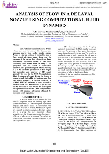
Transcription
Design and Computational Fluid Dynamics Analysis of an Idealized Modern WingsuitMaria E. FergusonWashington University in St. LouisAdvisor: Dr. Ramesh K. AgarwalAbstractThe modern wingsuit has been the subject of few scientific studies to date; the prevailingdesign process remains the dangerous “guess-and-check” method. This study employedthe commercial CFD flow solver ANSYS Fluent to solve the steady Reynolds AveragedNavier-Stokes equations with several turbulence models. The computational fluiddynamics (CFD) results provided information on the flow about a wingsuit designed withan airfoil cross section and relatively large planform with aspect ratio 1.3 at a Reynoldsnumber of 5.5 106. The CFD simulations were performed using the k-kl-ω Transitionturbulence model for the 2D Gottingen 228 airfoil and with the Spalart-Allmarasturbulence model for the 3D wingsuit. Although the lack of experimental data availablefor the wingsuit flight makes the true CFD validation difficult, the results for the 3Dwingsuit were analyzed and compared to the 2D airfoil, for which the computations werevalidated against the data from the airfoil/wing management software Profili 2.0. TheGottingen 228 airfoil had a maximum lift coefficient of 1.97 and a stall angle of 13 . Thewingsuit had a maximum lift coefficient of 2.73 and reached a stall angle of 48 , which ishigher than that of the 2D airfoil due to the 3D planform and induced drag. Thecomputational results indicate that the wingsuit as designed shows promise and couldlikely perform well under typical wingsuit flying conditions.IntroductionUnlike a hang glider, jet pack, or small plane, the wingsuit avoids excessive apparatus or motorsand allows the flyer to glide on his/her power. It is made of flexible and durable parachute fabricthat inflates while in flight. Wingsuit connects the limbs to create a wing with as much lift aspossible given the limitations of the human body. The modern wingsuit has only been inexistence since the 1990s [1], and although academics and manufacturers have begun to take amore scientific approach to wingsuit design, only a handful of truly rigorous analyses have beendone thus far. The lack of information on wingsuit aerodynamics puts designers and flyers at adangerous disadvantage; however the computational fluid dynamics (CFD) approaches canprovide risk-free information prior to the experimental trial stage.The first step in creating a computer simulation of a wingsuit in flight is to generate the geometryof the wingsuit. Partly due to issues of intellectual property along with the flexible nature of thewingsuit, it is difficult to generate a geometry that exactly matches a commercial wingsuit. Inaddition, computational limitations require that for the present, the wingsuit should be assumedrigid. The project was therefore approached in an idealized fashion: at a certain instant in time,the wingsuit has a certain shape and the rigid geometry reflects that shape at that moment.Furthermore, the ideal cross section for a wingsuit is an airfoil, although the contours of thehuman body and the flexible fabric make this ideal unattainable. The cross section of thewingsuit in this study was assumed to be an airfoil. The idealized scenario lent itself to acomparison of the 2D results for the chosen airfoil cross section and the 3D results for thewingsuit geometry, since the theoretical analyses already exist to compare a wing and its cross
section. Although there is no experimental data readily available for wingsuits, the airfoil/wingmanagement software Profili 2.0 is used to generate lift and drag data, which is then used tovalidate the 2D airfoil case.In 2D, the angle of attack of the air coming towards the leading edge of the airfoil is the angle ofattack the airfoil experiences. In wing theory, however, the airfoil cross sections on the wingexperience an induced drag caused by the downwash, a phenomenon where a small velocitycomponent points downward toward the wing upper surface [2]. This leads to an induced angleof attack, which must be subtracted from the geometric angle of attack to obtain the effectiveangle of attack (the term “angle of attack” in the following text and plots shall indicate thegeometric angle of attack unless mentioned otherwise).The effective angle of attack for a wing isthen calculated as [2]𝛼𝑒𝑓𝑓 𝛼 𝛼𝑖(1)where 𝛼 is the geometric angle of attack and 𝛼𝑖 is the induced angle of attack. The induced angleof attack is easily calculated by approximating the wingsuit as an elliptic wing. This is a bigassumption, but here the motivation is to observe a trend rather than obtain exact values,therefore it is sufficient as an approximation. The following equation from [2] is then used todetermine 𝛼𝑖 .𝛼𝑖 𝐶𝐿(2)𝜋𝐴𝑅When the plot of lift coefficient vs. angle of attack for a 2D airfoil is compared to that of a 3Dwing, it is expected that the 3D curve will reach a higher angle of attack before stall and willhave a somewhat similar slope according to the relation given in [2]:𝑑𝐶𝐿𝑑𝛼 𝑎 𝑎01 (3)𝑎0𝜋𝐴𝑅(1 𝜏)The value of τ varies depending upon the wing planform; τ 0 for an elliptic wing.GeometryDue to the flexible nature of the wingsuit, it is all butimpossible to pinpoint its exact geometry in flight. Thegeometry was designed as an idealized approximation of thetypical planform and cross section of suits currently on themarket. The human body, including head, hands, feet, andbody contours, was excluded from the geometry, as was theparachute pack that typically rests like a backpack over theflyer’s back.Since the design was meant to reflect the ideal wingsuit, it wascreated with an airfoil cross section. The 2D airfoil section wasFigure 1: Wingsuit Planform
chosen for its thickness and high camber so as to have a large lift coefficient.The 3D geometry was created with Autodesk Inventor 2016 by utilizing the “loft” feature alongthe line of the planform to connect a center airfoil cross section to a smaller airfoil cross sectionon the wing edge. The resulting wingsuit had an airfoil cross section at any section except at thevery outer edges, where the airfoil cross section was parallel to the angled wing edge. The edgeson the lower half of the suit, near the legs, were unrealistically thin due to the constraints of theCAD software. The thin areas are visible as the triangular portions on the lower left and right inFigure 1. The wingspan and height of the suit were designed to be 1.81 m so that the suit couldaccommodate the body of a tall human.Some suits have cutouts, making a forward wing on the arms and another wing between the legs.Others stretch the fabric such that the forward wing reaches all the way to the legs as shown inFigure 1. The planform was created in imitation of the relatively larger aspect ratio suitsdesigned for more experienced flyers. The aspect ratio of the final geometry was 1.3.Mesh Generation in ICEMThe 2D C-mesh for the airfoil validation case was created in the ANSYS meshing softwareICEM with a 25 m far field and an airfoil chord length of 1 m as shown in Figure 2. The finalmesh after refinement had approximately 100,000 elements with a finer grid near the airfoil andin its wake. A more detailed view of the geometry near the airfoil is also shown in Figure 2.Figure 2: C-Mesh with 25 m far field (right), with detailed view near airfoil (left)The 3D mesh was also created in ICEM and had a far field in the shape of an elliptical spheroidwith major axis 60 m, minor axis 30 m, width 12 m, and a symmetry plane that cut through themiddle of the wingsuit geometry. Near the wingsuit, a dense mesh region was created to achievefiner resolution closer to the geometry. The final mesh had approximately 2.4 million elements.Both meshes are shown in Figure 3.
Since there were no experimental or literature values for the wingsuit, it was of vital importanceto prove the grid independence of the CFD solution that is to show that the numerical resultswere not dependent on the mesh and that a finer mesh would yield the same results as a relativelycoarser mesh. The finer mesh was generated with the same geometry and far field, but with asmaller global element size and three dense regions with increasing mesh density towards thecenter. This mesh had approximately 7.4 million elements.Figure 3: 2.4 million element wingsuit mesh (left) and 7.4 million element wingsuit mesh with threedense mesh regions (right)Numerical Setup in ANSYS FluentThe 2D airfoil case was run with a pressure-based, viscous, incompressible flow solver using thetransition k-kl-ω turbulence model. The entire geometry was scaled down by a factor of 0.1 toreduce the chord length from 1 m to 0.1 m to reduce the Reynolds number to 2.4 105, a value forwhich the computed results could be compared to values in Profili 2.0. The semi-circle in frontof the leading edge of the airfoil in Figure 2 was considered a velocity inlet with a magnitude of45 m/s, which is a reasonable value for a wingsuit flight and provides the best glide ratio at acomfortable speed [3]. The downstream boundary of the computational domain was considereda pressure outlet.The SIMPLE solution scheme with second order upwind discretization for the momentumequations was employed. The 2D airfoil case was run for angles of attack from 0 to 14 in stepsof two degrees until the lift and drag coefficients for each angle of attack converged.The 3D wingsuit case was run with a pressure-based, viscous solver using the Spalart-Allmarasturbulence model with air density set to that of ideal gas. The plane cutting the geometry in halfwas set as a symmetry plane and the far field was set as a pressure far field. The free streamMach number was set at 0.132, which corresponds to a velocity of 45 m/s. The resultingReynolds number was approximately 3.5 106. The planform area was set at 1 m2 in order toobtain the non-dimensionalized lift and drag coefficients; these values would be later multipliedby the planform half area, 1.25 m2, to obtain the values for the lift and drag coefficients for thedesigned wingsuit. The length of the wingsuit was set at 1.84 m due to a slight measurementerror (the actual length was 1.81 m). The moment coefficient was calculated about the quarterchord, at 0.46 m along the x-direction.The SIMPLE solution scheme with second order upwind discretization for the momentumequations was also used for the 3D case. The case was run for angles of attack from 0 to 50 in
steps of two degrees until the lift and drag coefficients at each angle of attack converged within aspecified tolerance of less than one percent.Numerical Results for 2D Airfoil and 3D Wingsuit2D Airfoil ResultsThe Reynolds number for the 2D airfoil case was 2.4 105 assuming the air properties at 10,000ft. and a chord length of 10 cm. The software Profili 2.0 provides the airfoil data up to the angleof stall, and this data was compared to the data obtained from Fluent using the k-kl-ω model asshown in Figure 4 andFigure 5. The largest error was at 0 angle of attack, with theFluent data 19% and 45% lower than the Profili data for lift and drag coefficient respectively.Otherwise, the data matched well and showed a maximum lift coefficient of 1.97 and stall after12 as predicted by Profili. The success of the 2D validation case provided greater confidence forsimulation of the 3D case.Figure 4: Drag coefficient from Profili 2.0and FluentFigure 5: Lift coefficient from Profili 2.0and Fluent3D Wingsuit ResultsThe 3D cases converged within several thousand iterations until about 26 angle of attack, afterwhich point the convergence history showed some oscillations. By 46 angle of attack, the caseswere run for tens of thousands of iterations, but eventually the oscillations became small enoughto consider the solution converged. The lift increased linearly until 48 angle of attack, at whichpoint a large drop in lift became evident. Thus, 48 was considered as the stall angle for theFigure 6: Coefficients of lift, drag, and moment vs. angle ofattack for the wingsuit
wingsuit. The coefficients of lift, drag, and moment were multiplied by the wingsuit area toobtain the results shown in Figure 6, with a maximum lift coefficient of 2.73.The quality of these results was evaluated in two ways: testing for mesh independence andcomparing the 3D wingsuit curves to the 2D airfoil curves. The mesh independence test at 6 and12 angles of attack produced the same results for 𝐶𝐷 , 𝐶𝐿 , and 𝐶𝑚 with less than 1% error,proving that the results were independent of the mesh.When the 3D lift curve was compared to the 2D curve, a surprisingly large value was obtainedfor stall close to 48 and the 3D slope of the lift curve was lower than expected from Equation(3). Based on an airfoil lift curve slope of 0.0987, the expected elliptic wing lift curve slopewould give 0.0975. Although the value of τ for this unusual geometry is unknown, τ usuallyranges from 0.05 to 0.25, which gives the potential predicted wing lift curve slope in the range0.0972 to 0.0975. The lift curve slope obtained from CFD was 0.0577 as shown in Figure 7.Figure 7: Comparison of 2D airfoil and 3D wingsuit lift coefficients vs.geometric angle of attack with linear curve fitsThe discrepancy between the predicted slope 𝑎 and that obtained by CFD can be partiallyexplained by the phenomenon of the effective angle of attack. In fact, although the effectiveangle of attack given by Equation (3) assumes an elliptic wing and is therefore highlyapproximate, it demonstrates that the effective angle of attack is smaller than the geometric angleof attack. The effective angle of stall is thus between 27 and 32 rather than 48 . The inducedangle of attack is large, and would be even larger if it could be calculated without the ellipticplanform assumption. Plotting the 3D CFD results against the effective angle of attack ratherthan the geometric one brings the slope much closer to the expected value, with a value of0.0964 as shown in Figure 8. Again, this result comes about from a big assumption and should
not be taken as numerically accurate, but the fact that the data shifts in the correct direction andcomes closer to the expectation is reassuring.Figure 9: Comparison of 2D airfoil and 3D wingsuit lift coefficients vs. effectiveangle of attack with linear curve fitsKnowing more about the airflow as the angle of attack increases is useful in understanding howthe wingsuit would behave in actual flight conditions. The 2D pressure plots for various crosssections of the wingsuit were generated with the sectional views as shown in Figure 9.Figure 8: 2D cross sections and locations A through D at z 0.000, 0.332, 0.617, and 0.822 mfrom center line of the wingsuit
The pressure plots are given in Figure 10. For each cross section, the pressure coefficient isplotted at 24, 32, 40, and 48 angles of attack. The plots show the expected trend in which thesuction peak at the front of the airfoil increases with angle of attack until stall, at which point itFigure 10: Pressure coefficient vs. x/c for 8, 16, 24, 32, 40, and 48 angles of attack at z 0.000 m, 0.332 m, 0.617 m, and 0.822 m from centerline of the wingsuitbegins to decrease.Finally, the flow can also be visualized in 3D. Figure 11 shows the velocity streamlines coloredby the turbulent eddy viscosity, which demonstrate the typical vortical motion near the edges of awing. Figure 11 shows the wing tip vortices at 12 and 32 angle of attack; the motion from thewing tips increases in size and generated turbulence as the angle of attack increases. In Figure12, the pressure contours on the wingsuit are visible as well as the velocity streamlines. Theedges of the wing also show lower pressure zones, and there is higher pressure on the back sideof the airfoil than on the front side.Figure 11: 3D wingsuit at 45 m/s and 12 (left) and 32 (right) angles of attack with streamlinescolored by modified turbulent viscosity
Figure 12: 3D wingsuit at 45 m/s and 32 angle of attack with surface pressure contours andvelocity streamlines from wing edgesConclusions and Future WorkOne of the major problems in research related to wingsuits is the lack of information available inthe literature; however each research project helps lay the groundwork for the next project andeventually they will result in a more solid foundation to build upon. This study turned the lack ofinformation on wingsuit geometry into an opportunity to examine the behavior of an idealwingsuit with an airfoil cross section. Future work might include more realistic geometries thattake into account human features, and perhaps a flexible geometry that simulates the motion ofthe flexible wingsuit fabric. Using the pressure coefficient data and velocity streamlines, moredetails should be acquired regarding the changes in the behavior of the airflow about thewingsuit as the angle of attack is increased. Although the validation techniques for the 3D caseseemed to indicate that the results of this simulation were reasonable, the values should becompared to experimental data if possible. It might also be worthwhile to run the same caseswith different turbulence models to gain more confidence in the simulation results.References[1] W. S. Weed, "The Flight of the Bird Men," 18 June 2003. [Online].[2] J. John D. Anderson, Fundamenals of Aerodynamics, New York, NY: McGraw Hill, 2011.[3] G. Robson and R. D'Andrea, "Longitudinal Stability Analysis of a Jet-Powered Wingsuit,"AIAA Guidance, Navigation, and Control Conference, 2010.
AcknowledgementsI would like to extend my sincerest thanks to Dr. Ramesh Agarwal for his support of anunconventional topic and his guidance throughout the entire design and analysis process. I wouldalso like to thank Dr. Qiulin Qu, whose input was invaluable to this project. Thanks to fellowCFD lab member Boshun Gao for his instructions and assistance with ANSYS software. Finally,an enormous thank to the NASA – Missouri Space Grant Consortium for the funding that madethis project possible.BiographyMaria Ferguson is a Master’s of Aerospace Engineering candidate in the department ofMechanical Engineering and Materials Science at Washington University in St. Louis. Shegraduated with honors with a Bachelor of Arts from Saint Mary’s College and a Bachelor ofScience in Mechanical Engineering from Washington University in 2016 through the DualDegree program. Hailing from Napa, California, she hopes to secure a position as anAerodynamics Engineer in industry after graduation and one day fly her own wingsuit.
dangerous disadvantage; however the computational fluid dynamics (CFD) approaches can provide risk-free information prior to the experimental trial stage. The first step in creating a computer simulation of a wingsuit in flight is to generate the geometry . ICEM with a 25 m far field and an airfoil chord length of 1 m as shown in Figure 2 .