Transcription
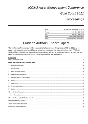
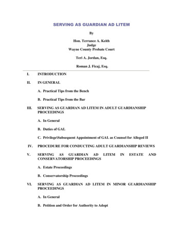
Vol.2, No.1ISSN Number (online): 2454-9614Proceedings of International Conference on Recent Trends in Mechanical Engineering-2K15(NECICRTME-2K15), 20th – 21st November,2015ANALYSIS OF FLOW IN A DE LAVALNOZZLE USING COMPUTATIONAL FLUIDDYNAMICSCH. Sriivasa Chakravarthy1, R.Jyothu Naik2Mechanical Engineering,Narasarao Peta Engineering College, Narasaraopet, A.P., India 1Assistant Professor, Mechanical Engineering, Narasaraopet Engineering College, A.P, India actHot exhaust gases expand in the divergingsection of the nozzle as the Mach number increasesfrom one. The pressure of these gases decreases asenergy is used to accelerate the gas. The nozzle isusually designed in such a way that the exit area islarge enough to accommodate the requisite massflow. It is under this condition that the thrustreaches maximum and the nozzle is said to beadapted, also called optimum or correct expansion.Rocket engines produce thrust by creating a highspeed fluid exhaust. This fluid is generally always agas which is created by high pressure (10-200 bar)combustion of solid or liquid propellants,consisting of fuel and oxidizer components, withina combustion chamber.De Laval nozzles are mechanical deviceswhich are used to convert the thermal andpressure energy into useful kinetic energy.Nozzle is a device designed to control the rate offlow, speed, direction, mass, shape and thepressure of the stream that exhaust from them.Convergent divergent nozzle is the mostcommonly used nozzle since in using it thepropellant can be heated in combustionchamber. The general range of exhaust velocityis 2 to 4.5 kilometer per second. In this projectthe designing and analysis of CD nozzlegeometry is done in the CFD (ComputationalFluid Dynamics software). Firstly the design ofnozzle is made in CATIA V-5 software and thenthe nozzle geometry is further analyzed inANSYS FLUENT software in order to analyzethe flow inside the CD nozzle and to get the viewof the behavior of fluid inside the convergentdivergent section of nozzle. And compare theseresults with manual calculation obtained bystandard nozzle equations.1. INTRODUCTIONA Rocket engine is a jet engine that usesspecific propellant mass for forming high speedpropulsive exhaust jet. Rocket engines are reactionengines and obtain thrust in accordance withNewton's third law of motion. Most rocket enginesare internal combustion engines. Rocket enginesare in a group that have maximum exhaustvelocities, are the lightest, and are the least energyefficient of all types of jet engines. The rockets arepowered by exothermic chemical reactions of therocket propellants used.Fig: Parts of rocket nozzle2. LITERATURE REVIEWK. M. PANDEY, S. K. YADAV [1] “Cfd AnalysisOf A Rocket Nozzle With Two Inlets At Mach2.1”. Ms. B. Krishna Prafulla, Dr. V. Chitti Babuand Sri P. Govinda Rao [2] “CFD Analysis ofConvergent Divergent Supersonic Nozzle”. BijuKuttan P, M Sajesh [3]“Optimization ofDivergent Angle of a Rocket Engine adhi Natta, V. Ranjith Kumar [4] Dr.Y. V. Hanumantha Rao “Flow Analysis of188South Asian Journal of Engineering and Technology (SAJET)
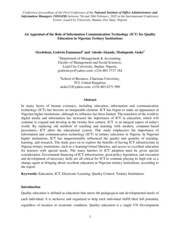
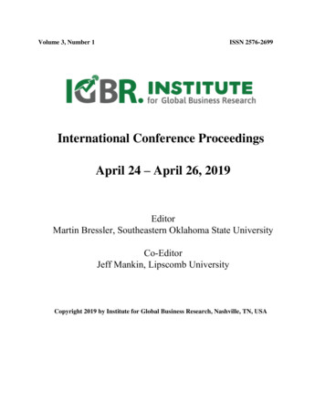
Vol.2, No.1ISSN Number (online): 2454-9614Proceedings of International Conference on Recent Trends in Mechanical Engineering-2K15(NECICRTME-2K15), 20th – 21st November,2015Rocket Nozzle Using Computational FluidDynamics (CFD)”. K.M. PANDEY , MemberIACSIT and A.P. Singh [5] “CFD Analysis ofConical Nozzle for Mach 3 at Various Angles ofDivergence with Fluent Software”.3. MATHEMATICAL FORMULATIONSNewton’s Third law of motion: It states that forevery action, there is always an equal and oppositereaction; or the mutual actions of two bodies uponeach other are always equal.Fig: Line diagram of De Laval nozzleStandard Dimensions To draw the nozzle in ANSYS FLUENT,the standard dimensions of nozzle aretaken from International Journal ofMechanical and Production Engineering. Total length of nozzle 484 mm Inlet diameter 166 mm Throat diameter 35mm Outlet diameter 183 mm Convergent angle 32 degrees Divergent angle 11 degreesTable-1: Theoretical Results Obtained By UsingBasicRelations with Different Mach NumberssectionAEInlet pressure 100 bar Inlet temperature 3300kNozzle PropertiesName: TungstenSymbol: WAtomic Number: 74Atomic Mass: 183.84 amuMelting Point: 3410.0 C (3683.15 K, 6170.0 F)Boiling Point: 5660.0 C (5933.15 K, 10220.0 F)Number of Protons/Electrons: 74Number of Neutrons: 110Classification: Transition MetalCrystal Structure: CubicDensity @ 293 K: 19.3 g/cm3Color: 1.681724.90Boundary Conditions Velocity(m/secT)4. COMPUTATIONAL FLUID DYNAMICSComputational Fluid Dynamics is the science ofpredicting fluid flow, heat transfer, mass transfer,chemical reactions, and related phenomena bysolving the mathematical equations which governthese processes using a numerical process i.e. on acomputer). Computational Fluid Dynamics, orCFD, is the use of mathematical techniques tomodel fluid flow. You can use CFD to create avirtual prototype of your product or process inorder to better understand its performance andimprove its design.189South Asian Journal of Engineering and Technology (SAJET)
Vol.2, No.1ISSN Number (online): 2454-9614Proceedings of International Conference on Recent Trends in Mechanical Engineering-2K15(NECICRTME-2K15), 20th – 21st November,2015Computational Fluid Dynamics (CFD) provides aqualitative (and sometimes even quantitative)prediction of fluid flows by means of mathematicalmodeling(partialdifferential equations) numerical methods (discretization andsolution techniques) software tools (solvers, pre- and postprocessing utilities)APPLICATIONS OF CFDMeshingAfter modeling of the nozzle, its meshing was doneusing ANSYS ICEM CFD software. The mesh ascreated of trigonal elements with element size1mm near the wall of the nozzle, five prism Layersof 0.4 mm height and height ratio 1.3 were createdso as to capture boundary layers finely.Applications of CFD are numerous.i.ii.iii.iv.v.vi.Flow and heat transfer in industrialprocesses (boilers, heat exchangers,combustionequipment,pumps,blowers, piping, etc.).Aerodynamics of ground vehicles,aircraft, missiles.Film coating, thermoforming inmaterial processing applications.Flow and heat transfer in propulsionand power generation systems.–Ventilation, heating, and coolingflows in buildings.Chemical vapor deposition (CVD) forintegrated circuit manufacturing.Pre-ProcessingPre-processing of the nozzle was done in ANSYSFLUENT. 2-D and double precision settings wereused while reading the mesh. The mesh was scaledsince allDimensions were initially specified in mm. Themesh was checked in fluent and no critical errorswere reported.SolutionThe Solution Was Converged After 977 Iterations.And The Order Of Scaled Residuals Was Below10e-3.Table-3: SolutionHeat transfer for electronics packagingapplications.5. COMPUTER SIMULATIONCFD is an engineering toolexperimentation. The followingperformed in CFD of nozzle:that assistssteps were1. Modeling2. Meshing3. Pre-Processing4. Solution5. Post-ProcessingModeling The 2-Dimensional modeling of thenozzle was done using CATIA-V5 and file wassaved in .stp format. The dimensions of the deLaval nozzle are presented in the table givenbelow.Table 2: Nozzle dimensionsSolutioncontrolsCoutrant number : 5SolutioninitializationCompute from : inletRuncalculationCheck caseNumber of iterations 2000Click calculationTable-4 convergence criteriaParameterTotal nozzlelength(mm)Inlet diameter(mm)Throat diameter(mm)Outlet diameter(mm)Chamber length(mm)Convergentangle(deg)Divergent angle(deg)Throat 34.518399.933211.3170ResidualsAbsolute 001Energy0.001K0.001Epsilon0.00140190South Asian Journal of Engineering and Technology (SAJET)
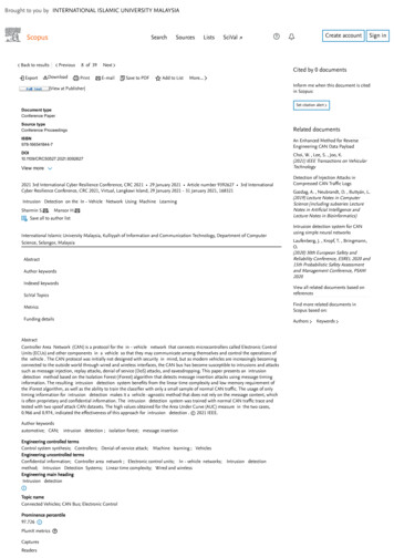
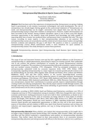
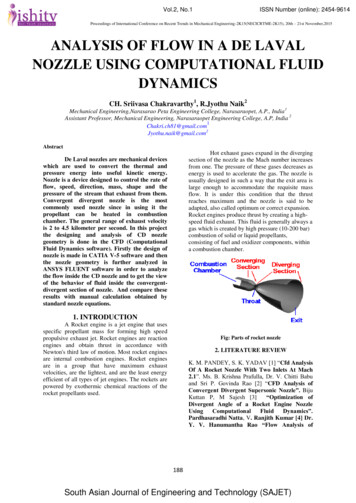
Vol.2, No.1ISSN Number (online): 2454-9614Proceedings of International Conference on Recent Trends in Mechanical Engineering-2K15(NECICRTME-2K15), 20th – 21st November,2015Post ProcessingTable-5: Graphics, Animation and PlotsGraphics&Animationplotsuse contour option to getvelocity magnitude, staticpressure , total temperatureand turbulenceintensitycontoursFig.Contours of temperatureuse XY plots to get staticpressure vsposition,velocitymagnitudevsposition andturbulenceintensity vs position6. RESULTS AND DISCUSSIONSFollowing are the contour plots that were obtained1)Velocity Contours: The velocity is minimum atthe inlet and goes on increasing till the nozzle exit.The velocity magnitude is Mach 1 at the throatsection of the nozzle. This condition is known aschoked flow condition. The velocity at the nozzleexit is 2400.32 m/sec, which is around Mach 3.03.Fig.Contours of static temperature3) Pressure Contours: The pressure is maximum atthe inlet and goes on decreasing till the outlet. Thestatic pressure at the outlet is 0.927 bar. There issudden decrease in pressure due to shock wave justafter the throat section.Fig.Contours of pressureFig.Contours of velocityFig.Contours of velocity magnitudeFig.contours of static pressure2) Temperature Contours: The temperature ismaximum at the inlet and goes on decreasing tillthe outlet. The magnitude of temperature at theoutlet is 1760.89 K.191South Asian Journal of Engineering and Technology (SAJET)
Vol.2, No.1ISSN Number (online): 2454-9614Proceedings of International Conference on Recent Trends in Mechanical Engineering-2K15(NECICRTME-2K15), 20th – 21st November,20158. REFFERENCES7. CONCLUSIONS1.The results obtained by Computational FluidDynamics (CFD) are almost identical to thoseobtained theoretically. The tables below comparetheoretical results to CFD results.Table-6: Comparison of values in taken fromtheoretical and from 24.1761.687.520.32900.893.4.5.0.9276.7.8.9.K. M. PANDEY , S. K. YADAV JournalofEnvironmentalResearchAndDevelopment Vol. 5 No. 2, OctoberDecember 2010 , “CFD ANALYSIS OFA ROCKET NOZZLE WITH TWOINLETS AT MACH 2.1”Ms. B. Krishna Prafulla, Dr. V. ChittiBabuand Sri P. Govinda RaoInternational Journal of ComputationalEngineering Research , Volume 03 , Issue5 “CFD Analysis of Convergent –Divergent Supersonic Nozzle”Biju Kuttan P, M Sajesh ;TheInternational Journal Of Engineering AndScience (Ijes) Volume 2 ,Issue 2 , Pages:196-207 , 2013, Issn: 2319 – 1813 Isbn:2319 – 1805“Optimization ofDivergent Angle of a Rocket EngineNozzle Using Computational FluidDynamics”Pardhasaradhi Natta, V. Ranjith Kumar,Dr. Y. V. Hanumantha Rao InternationalJournal of Engineering Research andApplications (IJERA) ISSN: 2248-9622Vol. 2, Issue 5, September- October 2012,pp.1226-1235“Flow Analysis of Rocket Nozzle UsingComputational Fluid Dynamics (CFD)”K.M. PANDEY , Member IACSIT andA.P. Singh , International Journal ofChemical Engineering and Applications,Vol. 1, No. 2, August 2010 ISSN: 20100221 “CFD Analysis of Conical Nozzlefor Mach 3 at Various Angles ofDivergence with Fluent Software”A.A. Khan and T.R Shem Bharkar,“Viscous Flow Analysis In A ConvergentDivergent Nozzle” proceeding of theinternational conference on aerospacescience andTechnology, Bangalore,India, June 26-28,2008H . K .Versteeg and W. Malala SekharaAn Introduction To Computational FluidDynamics, British library Cataloguingpup, 4th edition,1996David C. Will Cox Turbulence Modelingfor CFD second edition 1998Kazuhiro Nakahahi “ Navier StrokesComputations Of Two And ThreeDimensional Cascade Flow Fields”192South Asian Journal of Engineering and Technology (SAJET)
4. COMPUTATIONAL FLUID DYNAMICS Computational Fluid Dynamics is the science of predicting fluid flow, heat transfer, mass transfer, chemical reactions, and related phenomena by solving the mathematical equations which govern these processes using a numerical process i.e. on a computer). Computational Fluid Dynamics, or