Transcription
Mechanical ScienceHeat ExchangersDOE FUNDAMENTALSMECHANICAL SCIENCEMODULE 2HEAT EXCHANGERS
Mechanical ScienceHeat ExchangersTABLE OF CONTENTSTABLE OF CONTENTS . iLIST OF FIGURES . iiLIST OF TABLES. iiiREFERENCES . ivOBJECTIVES . vTYPES OF HEAT EXCHANGERS . 1Introduction . 1Types of Heat Exchanger Construction . 1Types of Heat Exchangers . 3Comparison of the Types of Heat Exchangers. 5Summary . 9HEAT EXCHANGER APPLICATIONS .10Introduction .10Preheater .10Radiator.11Air Conditioner Evaporator and Condenser .12Large Steam System Condensers .12Summary .15MS-02-i
Mechanical ScienceHeat ExchangersLIST OF FIGURESFigure 1 Tube and Shell Heat Exchanger . 2Figure 2 Plate Heat Exchanger . 3Figure 3 Parallel Flow Heat Exchanger . 4Figure 4 Counter Flow Heat Exchange . 4Figure 5 Cross Flow Heat Exchanger . 5Figure 6 Single and Multi-Pass Heat Exchangers . 7Figure 7 Regenerative and Non-Regenerative Heat Exchangers . 8Figure 8 U-tube Feedwater Heat Exchanger . 11Figure 9 Single Pass Condenser . 13Figure 10 Jet Pump . 14MS-02-ii
Mechanical ScienceHeat ExchangersLIST OF TABLESNONEMS-02-iii
Mechanical ScienceHeat ExchangersREFERENCES Babcock & Wilcox, Steam, Its Generations and Use 41st Edition, Babcock & Wilcox Co. Cheremisinoff, N. P., Fluid Flow, Pumps, Pipes and Channels, Ann Arbor Science. Heat Transfer, Thermodynamics and Fluid Flow Fundamentals, Columbia, MD, GeneralPhysics Corporation, Library of Congress Card #A 326517. SPX Cooling Technologies, Cooling Tower Fundamentals, SPX Cooling Technologies.MS-02-iv
Mechanical ScienceHeat ExchangersOBJECTIVESTERMINAL OBJECTIVE1.0Without references, DESCRIBE the purpose, construction, and principles of operationfor each major type of heat exchanger: parallel flow, counter flow, and cross flow.ENABLING OBJECTIVES1.1STATE the two types of heat exchanger construction.1.2Provided with a drawing of a heat exchanger, IDENTIFY the following internal parts:a. Tubesb. Tube sheetc. Shelld. Baffles1.3DESCRIBE hot and cold fluid flow in parallel flow, counter flow, and cross flow heatexchangers.1.4DIFFERENTIATE between the following types of heat exchangers:a. Single-pass versus multi-pass heat exchangers.b. Regenerative versus non-regenerative heat exchangers.1.5LIST at least three applications of heat exchangers.1.6STATE the purpose of a condenser.1.7DEFINE the following terms:a. Hotwellb. Condensate depression1.8STATE why condensers in large steam cycles are operated at a vacuum.MS-02-v
Mechanical ScienceHeat ExchangersTYPES OF HEAT EXCHANGERSIn almost any nuclear, chemical, or mechanical system, heat must be transferredfrom one place to another or from one fluid to another. Heat exchangers are usedto transfer heat from one fluid to another. A basic understanding of themechanical components of a heat exchanger is important to understanding howthey function and operate.EO 1.1STATE the two types of heat exchanger construction.EO 1.2Provided with a drawing of a heat exchanger, IDENTIFY the following internalparts:a.Tubesc.Shellb.Tube sheetd.BafflesEO 1.3DESCRIBE hot and cold fluid flow in parallel flow, counter flow, and crossflow heat exchangers.EO 1.4DIFFERENTIATE between the following types of heat exchangers:a.Single-pass versus multi-pass heat exchangers.b.Regenerative versus non-regenerative heat exchangers.IntroductionA heat exchanger is a component that allows the transfer of heat from one fluid (liquid or gas) toanother fluid. Reasons for heat transfer include the following:1.To heat a cooler fluid by means of a hotter fluid2.To reduce the temperature of a hot fluid by means of a cooler fluid3.To boil a liquid by means of a hotter fluid4.To condense a gaseous fluid by means of a cooler fluid5.To boil a liquid while condensing a hotter gaseous fluidRegardless of the function the heat exchanger fulfills, in order to transfer heat the fluids involvedmust be at different temperatures and they must come into thermal contact. Heat can flow onlyfrom the hotter to the cooler fluid.In a heat exchanger there is no direct contact between the two fluids. The heat is transferredfrom the hot fluid to the metal isolating the two fluids and then to the cooler fluid.Types of Heat Exchanger ConstructionAlthough heat exchangers come in every shape and size imaginable, the construction of mostheat exchangers fall into one of two categories: tube and shell, or plate. As in all mechanicaldevices, each type has its advantages and disadvantages.MS-02-1
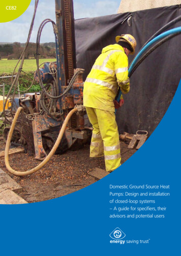
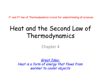
Mechanical ScienceHeat ExchangersTube and ShellThe most basic and the most common type of heat exchanger construction is the tubeand shell, as shown in Figure 1. This type of heat exchanger consists of a set of tubes ina container called a shell. The fluid flowing inside the tubes is called the tube side fluidand the fluid flowing on the outside of the tubes is the shell side fluid. At the ends of thetubes, the tube side fluid is separated from the shell side fluid by the tube sheet(s). Thetubes are rolled and press-fitted or welded into the tube sheet to provide a leak tightseal. In systems where the two fluids are at vastly different pressures, the higherpressure fluid is typically directed through the tubes and the lower pressure fluid iscirculated on the shell side. This is due to economy, because the heat exchanger tubescan be made to withstand higher pressures than the shell of the heat exchanger for amuch lower cost. The support plates shown on Figure 1 also act as baffles to direct theflow of fluid within the shell back and forth across the tubes.Figure 1 Tube and Shell Heat ExchangerPlateA plate type heat exchanger, as illustrated in Figure 2, consists of plates instead of tubesto separate the hot and cold fluids. The hot and cold fluids alternate between each of theplates. Baffles direct the flow of fluid between plates. Because each of the plates has avery large surface area, the plates provide each of the fluids with an extremely largeheat transfer area. Therefore a plate type heat exchanger, as compared to a similarlysized tube and shell heat exchanger, is capable of transferring much more heat. This isMS-02-2
Mechanical ScienceHeat Exchangersdue to the larger area the plates provide over tubes. Due to the high heat transferefficiency of the plates, plate type heat exchangers are usually very small whencompared to a tube and shell type heat exchanger with the same heat transfer capacity.Plate type heat exchangers are not widely used because of the inability to reliably sealthe large gaskets between each of the plates. Because of this problem, plate type heatexchangers have only been used in small, low pressure applications such as on oilcoolers for engines. However, new improvements in gasket design and overall heatexchanger design have allowed some large scale applications of the plate type heatexchanger. As older facilities are upgraded or newly designed facilities are built, largeplate type heat exchangers are replacing tube and shell heat exchangers and becomingmore common.Figure 2 Plate Heat ExchangerTypes of Heat ExchangersBecause heat exchangers come in so many shapes, sizes, makes, and models, they arecategorized according to common characteristics. One common characteristic that can be usedto categorize them is the direction of flow the two fluids have relative to each other. The threecategories are parallel flow, counter flow and cross flow.Parallel flow, as illustrated in Figure 3, exists when both the tube side fluid and the shell sidefluid flow in the same direction. In this case, the two fluids enter the heat exchanger from theMS-02-3
Mechanical ScienceHeat Exchangerssame end with a large temperature difference. As the fluids transfer heat, hotter to cooler, thetemperatures of the two fluids approach each other. Note that the hottest cold-fluid temperatureis always less than the coldest hot-fluid temperature.Figure 3 Parallel Flow Heat ExchangerCounter flow, as illustrated in Figure 4, exists when the two fluids flow in opposite directions.Each of the fluids enters the heat exchanger at opposite ends. Because the cooler fluid exits thecounter flow heat exchanger at the end where the hot fluid enters the heat exchanger, thecooler fluid will approach the inlet temperature of the hot fluid. Counter flow heat exchangers arethe most efficient of the three types. In contrast to the parallel flow heat exchanger, the counterflow heat exchanger can have the hottest cold-fluid temperature greater than the coldest hotfluid temperature.Figure 4 Counter Flow Heat ExchangeMS-02-4
Mechanical ScienceHeat ExchangersCross flow, as illustrated in Figure 5, exists when one fluid flows perpendicular to the secondfluid; that is, one fluid flows through tubes and the second fluid passes around the tubes at 90 angle. Cross flow heat exchangers are usually found in applications where one of the fluidschanges state (2-phase flow). An example is a steam system's condenser, in which the steamexiting the turbine enters the condenser shell side, and the cool water flowing in the tubesabsorbs the heat from the steam, condensing it into water. Large volumes of vapor may becondensed using this type of heat exchanger flow.Figure 5 Cross Flow Heat ExchangerComparison of the Types of Heat ExchangersEach of the three types of heat exchangers has advantages and disadvantages. But of thethree, the counter flow heat exchanger design is the most efficient when comparing heattransfer rate per unit surface area. The efficiency of a counter flow heat exchanger is due to thefact that the average T (difference in temperature) between the two fluids over the length of theheat exchanger is maximized, as shown in Figure 4. Therefore the log mean temperature for acounter flow heat exchanger is larger than the log mean temperature for a similar parallel orcross flow heat exchanger. (See the Thermodynamics, Heat Transfer, and Fluid FlowFundamentals Handbook for a review of log mean temperature). This can be seen bycomparing the graphs in Figure 3, Figure 4, and Figure 5. The following exercise demonstrateshow the higher log mean temperature of the counter flow heat exchanger results in a larger heattransfer rate. The log mean temperature for a heat exchanger is calculated using the followingequation.(2-1)Heat transfer in a heat exchanger is by conduction and convection. The rate of heat transfer,"Q", in a heat exchanger is calculated using the following equation.MS-02-5
Mechanical ScienceHeat ExchangersUoAoΔTlm(2-2)Where: Heat transfer rate (BTU/hr)Uo Overall heat transfer coefficient (BTU/hr-ft2- F)Ao Cross sectional heat transfer area (ft2)ΔTlm Log mean temperature difference ( F)Consider the following example of a heat exchanger operated under identical conditions as acounter flow and then a parallel flow heat exchanger.T1 represents the hot fluid temperatureT1in 200 FT1out 145 FUo 70 BTU/hr-ft2- FAo 75ft2T2 represents the cold fluid temperatureT2in 80 FT2out 120 F 72oF 61oFInserting the above values into heat transfer Equation (2-2) for the counter flow heat exchangeryields the following result.Therefore:Inserting the above values into the heat transfer Equation (2-2) for parallel flow heat exchangeryields the following result.Therefore:MS-02-6
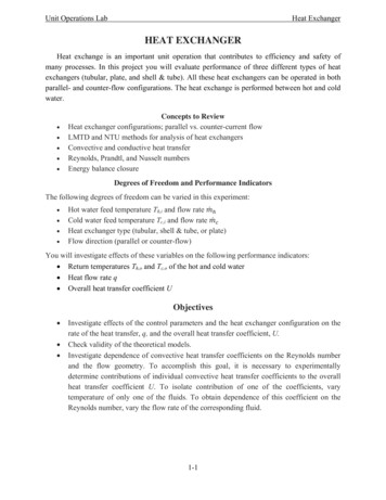
Mechanical ScienceHeat ExchangersThe results demonstrate that given the same operating conditions, operating the same heatexchanger in a counter flow manner will result in a greater heat transfer rate than operating inparallel flow.Figure 6 Single and Multi-Pass Heat ExchangersIn actuality, most large heat exchangers are not purely parallel flow, counter flow, or cross flow;they are usually a combination of the two or all three types of heat exchangers. This is due tothe fact that actual heat exchangers are more complex than the simple components shown inthe idealized figures used above to depict each type of heat exchanger. The reason for thecombination of the various types is to maximize the efficiency of the heat exchanger within therestrictions placed on the design. That is, size, cost, weight, required efficiency, type of fluids,operating pressures, and temperatures, all help determine the complexity of a specific heatexchanger.One method that combines the characteristics of two or more heat exchangers and improvesthe performance of a heat exchanger is to have the two fluids pass each other several timeswithin a single heat exchanger. When a heat exchanger's fluids pass each other more thanonce, a heat exchanger is called a multi-pass heat exchanger. If the fluids pass each other onlyonce, the heat exchanger is called a single-pass heat exchanger. See Figure 6 for an exampleof both types. Commonly, the multi-pass heat exchanger reverses the flow in the tubes by useof one or more sets of "U" bends in the tubes. The "U" bends allow the fluid to flow back andforth across the length of the heat exchanger. A second method to achieve multiple passes is toinsert baffles on the shell side of the heat exchanger. These direct the shell side fluid back andforth across the tubes to achieve the multi-pass effect.MS-02-7
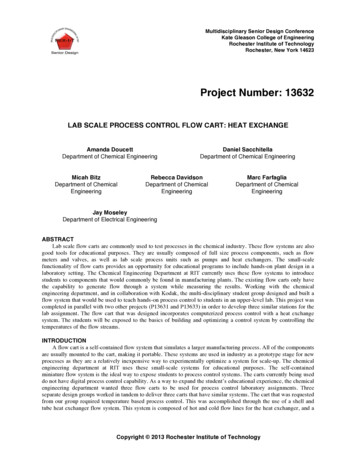
Mechanical ScienceHeat ExchangersHeat exchangers are also classified by their function in a particular system. One commonclassification is regenerative or nonregenerative. A regenerative heat exchanger is one in whichthe same fluid is both the cooling fluid and the cooled fluid, as illustrated in Figure 7. That is, thehot fluid leaving a system gives up its heat to "regenerate" or heat up the fluid returning to thesystem. Regenerative heat exchangers are usually found in high temperature systems where aportion of the system's fluid is removed from the main process, and then returned. Because thefluid removed from the main process contains energy (heat), the heat from the fluid leaving themain system is used to reheat (regenerate) the returning fluid instead of being rejected to anexternal cooling medium to improve efficiency. It is important to remember that the termregenerative/nonregenerative only refers to "how" a heat exchanger functions in a system, anddoes not indicate any single type (tube and shell, plate, parallel flow, counter flow, etc.).In a nonregenerative heat exchanger, as illustrated in Figure 7, the hot fluid is cooled by fluidfrom a separate system and the energy (heat) removed is not returned to the system.Figure 7 Regenerative and Non-Regenerative Heat ExchangersMS-02-8
Mechanical ScienceHeat ExchangersSummaryThe important information from this chapter is summarized below.Types of Heat Exchangers Summary There are two methods of constructing heat exchangers: plate typeand tube type. Parallel flow - the hot fluid and the coolant flow in the same direction. Counter flow - The hot fluid and the coolant flow in opposite Cross flow - the hot fluid and the coolant flow at 90 angles(perpendicular) to each other. The four heat exchanger parts identified were:oTubesoTube SheetoShelloBaffles Single-pass heat exchangers have fluids that pass other only once. Multi-pass heat exchangers have fluids that pass each other morethan once through the use of U tubes and baffles. Regenerative heat exchangers use the same fluid for heating andcooling. Non-regenerative heat exchangers use separate fluids for heatingand cooling.MS-02-9
Mechanical ScienceHeat ExchangersHEAT EXCHANGER APPLICATIONSThis chapter describes some specific applications of heat exchangers.EO 1.5LIST at least three applications of heat exchangers.EO 1.6STATE the purpose of a condenser.EO 1.7DEFINE the following terms:a. Hotwellb. Condensate depressionEO 1.8STATE why condensers in large steam cycles are operated at a vacuum.IntroductionHeat exchangers are found in most chemical or mechanical systems. They serve as thesystem's means of gaining or rejecting heat. Some of the more common applications are foundin heating, ventilation and air conditioning (HVAC) systems, radiators on internal combustionengines, boilers, condensers, and as preheaters or coolers in fluid systems. This chapter willreview some specific heat exchanger applications. The intent is to provide several specificexamples of how each heat exchanger functions in the system, not to cover every possibleapplicaton.PreheaterIn large steam systems, or in any process requiring high temperatures, the input fluid is usuallypreheated in stages, instead of trying to heat it in one step from ambient to the finaltemperature. Preheating in stages increases the plant's efficiency and minimizes thermal shockstress to components, as compared to injecting ambient temperature liquid into a boiler or otherdevice that operates at high temperatures. In the case of a steam system, a portion of theprocess steam is tapped off and used as a heat source to reheat the feedwater in preheaterstages. Figure 8 is an example of the construction and internals of a U-tube feedwater heatexchanger found in a large power generation facility in a preheater stage. As the steam entersthe heat exchanger and flows over and around the tubes, it transfers its thermal energy and iscondensed. Note that the steam enters from the top into the shell side of the heat exchanger,where it not only transfers sensible heat (temperature change) but also gives up its latent heatof vaporization (condenses steam into water). The condensed steam then exits as a liquid at thebottom of the heat exchanger. The feedwater enters the heat exchanger on the bottom right endand flows into the tubes. Note that most of these tubes will be below the fluid level on the shellside.This means the feedwater is exposed to the condensed steam first and then travels through thetubes and back around to the top right end of the heat exchanger. After making the 180 bend,the partially heated feedwater is then subjected to the hotter steam entering the shell side.MS-02-10
Mechanical ScienceHeat ExchangersFigure 8 U-tube Feedwater Heat ExchangerThe feedwater is further heated by the hot steam and then exits the heat exchanger. In this typeof heat exchanger, the shell side fluid level is very important in determining the efficiency of theheat exchanger, as the shell side fluid level determines the number of tubes exposed to the hotsteam.RadiatorCommonly, heat exchangers are thought of as liquid-to-liquid devices only. But a heatexchanger is any device that transfers heat from one fluid to another. Some of a facility'sequipment depend on air-to-liquid heat exchangers. The most familiar example of an air-toliquid heat exchanger is a car radiator. The coolant flowing in the engine picks up heat from theengine block and carries it to the radiator. From the radiator, the hot coolant flows into the tubeside of the radiator (heat exchanger). The relatively cool air flowing over the outside of the tubespicks up the heat, reducing the temperature of the coolant.Because air is such a poor conductor of heat, the heat transfer area between the metal of theradiator and the air must be maximized. This is done by using fins on the outside of the tubes.The fins improve the efficiency of a heat exchanger and are commonly found on most liquid-toair heat exchangers and in some high efficiency liquid-to-liquid heat exchangers.MS-02-11
Mechanical ScienceHeat ExchangersAir Conditioner Evaporator and CondenserAll air conditioning systems contain at least two heat exchangers, usually called the evaporatorand the condenser. In either case, evaporator or condenser, the refrigerant flows into the heatexchanger and transfers heat, either gaining or releasing it to the cooling medium. Commonly,the cooling medium is air or water. In the case of the condenser, the hot, high pressurerefrigerant gas must be condensed to a subcooled liquid.The condenser accomplishes this by cooling the gas, transferring its heat to either air or water.The cooled gas then condenses into a liquid. In the evaporator, the subcooled refrigerant flowsinto the heat exchanger, but the heat flow is reversed, with the relatively cool refrigerantabsorbing heat from the hotter air flowing on the outside of the tubes. This cools the air andboils the refrigerant.Large Steam System CondensersThe steam condenser, shown in Figure 9, is a major component of the steam cycle in powergeneration facilities. It is a closed space into which the steam exits the turbine and is forced togive up its latent heat of vaporization. It is a necessary component of the steam cycle for tworeasons. One, it converts the used steam back into water for return to the steam generator orboiler as feedwater. This lowers the operational cost of the plant by allowing the clean andtreated condensate to be reused, and it is far easier to pump a liquid than steam. Two, itincreases the cycle's efficiency by allowing the cycle to operate with the largest possible delta-Tand delta-P between the source (boiler) and the heat sink (condenser).Because condensation is taking place, the term latent heat of condensation is used instead oflatent heat of vaporization. The steam's latent heat of condensation is passed to the waterflowing through the tubes of the condenser.After the steam condenses, the saturated liquid continues to transfer heat to the cooling wateras it falls to the bottom of the condenser, or hotwell. This is called subcooling, and a certainamount is desirable. A few degrees subcooling prevents condensate pump cavitation. Thedifference between the saturation temperature for the existing condenser vacuum and thetemperature of the condensate is termed condensate depression. This is expressed as anumber of degrees condensate depression or degrees subcooled. Excessive condensatedepression decreases the operating efficiency of the plant because the subcooled condensatemust be reheated in the boiler, which in turn requires more heat from the reactor, fossil fuel, orother heat source.There are different condenser designs, but the most common, at least in the large powergeneration facilities, is the straight-through, single-pass condenser illustrated Figure 9. Thiscondenser design provides cooling water flow through straight tubes from the inlet water box onone end, to the outlet water box on the other end. The cooling water flows once through thecondenser and is termed a single pass. The separation between the water box areas and thesteam condensing area is accomplished by a tube sheet to which the cooling water tubes areattached. The cooling water tubes are supported within the condenser by the tube supportMS-02-12
Mechanical ScienceHeat ExchangersFigure 9 Single-Pass Condensersheets. Condensers normally have a series of baffles that redirect the steam to minimize directimpingement on the cooling water tubes. The bottom area of the condenser is the hotwell, asshown in Figure 9. This is where the condensate collects and the condensate pump takes itssuction. If noncondensable gasses are allowed to build up in the condenser, vacuum willdecrease and the saturation temperature at which the steam will condense increases.Non-condensable gasses also blanket the tubes of the condenser, thus reducing the heattransfer surface area of the condenser. This surface area can also be reduced if the condensatelevel is allowed to rise over the lower tubes of the condenser. A reduction in the heat transfersurface has the same effect as a reduction in cooling water flow. If the condenser is operatingnear its design capacity, a reduction in the effective surface area results in difficulty maintainingcondenser vacuum.The temperature and flow rate of the cooling water through the condenser controls thetemperature of the condensate. This in turn controls the saturation pressure (vacuum) of thecondenser.To prevent the condensate level from rising to the lower tubes of the condenser, a hotwell levelcontrol system may be employed. Varying the flow of the condensate pumps is one methodused to accomplish hotwell level control. A level sensing network controls the condensate pumpspeed or pump discharge flow control valve position. Another method employs an overflowsystem that spills water from the hotwell when a high level is reached.Condenser vacuum should be maintained as close to 29 inches Hg as practical. This allowsmaximum expansion of the steam, and therefore, the maximum work. If the condenser wereperfectly air-tight (no air or noncondensable gasses present in the exhaust steam), it would benecessary only to condense the steam and remove the condensate to create and maintain aMS-02-13
Mechanical ScienceHeat Exchangersvacuum. The sudden reduction in steam volume, as it condenses, would maintain the vacuum.Pumping the water from the condenser as fast as it is formed would maintain the vacuum. It is,however, impossible to prevent the entrance of air and other non-condensable gasses into thecondenser. In addition, some method must exist to initially cause a vacuum to exist in thecondenser. This necessitates the use of an air ejector or vacuum pump to establish and helpmaintain condenser vacuum.Air ejectors are essentially jet pumps or eductors, as illustrated in Figure 10. In operation, the jetpump has two types of fluids. They are the high pressure fluid that flows through the nozzle, andthe fluid being pumped which flows around the nozzle into the throat of the diffuser. The highvelocity fluid enters the diffuser where its molecules strike other molecules. These moleculesare in turn carried along with the high velocity fluid out of the diffuser creating a low pressurearea around the mouth of the nozzle. This process is called entrainment. The low pressure areawill draw more fluid from around the nozzle into the throat of the diffuser. As the fluid movesdown the diffuser, the increasing area converts the velocity back to pressure. Use of steam at apressure between 200 psi and 300 psi as the high pressure fluid enables a single-stage airejector to draw a vacuum of about 26 inches Hg.Figure 10 Jet PumpNormally, air ejectors consist of two suction stages. The first stage suction is located on top ofthe condenser, while the second stage suction comes from the diffuser of the first stage. Theexhaust steam from the second stage must be condensed. This is normally accomplished by anair ejector condenser that is cooled by condensate. The air ejector condenser also preheats thecondensate returning to the boiler. Two-stage air ejectors are capable of drawing vacuums to 29inches Hg.A vacuum pump may be any type of motor-driven air compressor. Its suction is attached to thecondenser, and it discharges to the atmosphere. A common type uses rotating vanes in anelliptical housing. Single-stage, rotary-vane units are used for vacuums to 28 inches Hg. Twostage units can draw vacuums to 29.7 inches Hg. The vacuum pump has an advantage over theair ejector in that it requires no source of steam for its operation. They are normally used as theinitial source of vacuum for condenser start-up.MS-02-14
Mechanical ScienceHeat ExchangersSummaryThe important information from this chapter is summarized below.Heat Exchanger Applications Summary Heat exchangers are often used in the following applications.oPreheateroRadiatoroAir conditioning evaporator and condenseroSteam condenser The purpose of a condenser is to remove the latent heat o
The fluid flowing inside the tubes is called the tube side fluid and the fluid flowing on the outside of the tubes is the shell side fluid. At the ends of the tubes, the tube side fluid is separated from the shell side fluid by the tube sheet(s). The tubes are rolled and press-fitted or