Transcription
Interim Technical ReportDIABIO CANYON UNIT 1INDEPENDENT DESIGN VERIFICATION PROGRAMHVAC DUCT AND SUPPORTS Re2%RTITR g 15 REVISION 0Docket No. 50-275License No. DPR-76Prospect/Z e8ZProject Engineer DateTechnical Review82i2i50170 82i2i3PDR ADQCKP05000275PDR Su 2/iQIFZManager DateApproved P 105-4-839-'315
1
HVACDuct and Supports ReportContentsList of TablesList of FiguresProgram llanager's Preface1.0IntroductionPurpose and ication llethodsLicensing Criteria4IDVPAnalysis of HVAC Duct and SupportsDuct Sample No. 13.1.1 llethod of IDVP Analysis555IDVP Design3.13.1.23.1.3.3.1.43.1.53.1.6Results ofIDVPAnalysisDesign Analysis liethodsComparison of IDVP andDesign Analysis llethodsComparison of IDVP and Designll1313Analysis ResultsEOIReports valuationDuct Sample No. 2blethod of IDVP AnalysisResults of IDVP AnalysisDesign Analysis llethodsComparison of IDVP and DesignAnalysis llethodsComparison of IDVP and DesignAnalysis ResultsEOIReports AAppendixAppendixAppendixBCDHosgri Response Spectra Consideredin the IDVP Analyses.EOI TablesKey bord DefinitionsProgram tlanager's Assessment
zfEia.iTa.hlaaTitle.Vertical DuctResultsand Duct SupportsHorizontal DuctResultslland Duct SupportsComparison of IDVP and DesignAnalysis Results for HVAC DuctSample No.112Inch Duct Results2410Inch Duct Results2612Inch Duct Comparison28
Duct Sample No.1Computer llodel Duct SampleNo.1HorizontalRunComputer flodel Duct SampleNo.1VerticalDuct Sample No.12 Inch DuctRun217Duct Sample No. 212 Inch Duct, SupportDuct Sample No.10 Inch DuctDetail182Computer l1odelDuct Sample No. 2, 12 Inch Duct1920Computer blodelDiect Sample No. 2, 10 Inch Duct21
TELEDYNEENGINEERINQ SERVICES PROGRAM MANAGER'S PREFACEDIABLO CANYON NUCLEARPOWER PLANT-UNITIINDEPENDENT DESIGN VERIFICATION PROGRAMINTERIM TECHNICAL REPORTHVAC DUCTS AND SUPPORTSThis is the fifteenth of a series of Interim Technical Reportsprepared by the DCNPP-IDVP for the purpose of providing a conclusionof the program.This report provides the analytical results, recommendations andconclusions of the IDVP with respect to the initial sample for HVACducts and supports.All EOI files initiated for the HVAC duct andsupport sample have been closed or identifiederror.Engineering Services hasapproved this ITR including theconclusions and recommendationspresented.The methodology followed by TES in performing this reviewand evaluation is described in Appendix D to this report.As as anIDVPProgramManager,ITR Reviewed and ApprovedIDVP Program ManagerTeledyne Engineering ServicesAssistant ProjectManagerTeledyne
1.0INTRODUCTIONPurnzae and. KamaThis Interim Technical Report summarizes theindependent analysis and verification of the initialsample of HVAC ducts and duct supports at Diablo CanyonNuclear Power Plant Unit 1 (DCNPP-1).duct and duct support samples each consistof two sections of duct. Sample No. 1 of duct andassociated supports is located in the turbine buildingelevation ll9 feet. It provides ventilation to the4.16kV switchgear.Sample No. 2 of duct and associatedsupports is located in the auxiliary building elevation100 feet.It provides ventilation for the primarymake-up water pumps.The HVACThis report is one of several Interim TechnicalReports of the Independent Design Verification Program(IDVP). Interim Technical Reports (ITR) includereferences, sample definitions and descriptions,methodology, a listing of Error and Open Items, anexamination of trends and concerns, and a conclusion(Reference 1). This report presents the IDVP HVAC ductand duct support analyses, comparison with the designanalysis results and serves as a vehicle for NRC review.It will also be referenced in the Phase I final report.Robert L. Cloud and Associates(RLCA)performedverification analyses for two samples of HVAC duct andduct supports. Field verified information was used inboth hand and computer calculations to evaluate stresses.The results showed the samples of HVAC duct and ductsupports to be adequate to withstand the effects of thepostulated Hosgri event.
On September 28, 1981 PGandE reported that a diagramerror had been found in a portion of the SeismicQualification of the Diablo Canyon Nuclear Power Plant(DCNPP-1). This error resulted 'in an incorrectapplication of the seismic floor reponse spectra forsections of the annulus of the Unit 1 containmentbuilding. The error originated when PGandE transmitted asketch of Unit 2 to a seismic service-related contractor.This sketch contained geometry incorrectly identified asUnit 1 geometry.As a result of this error a seismic reverificationprogram was established to determine if the seismicqualification of the plant was adequate for thepostulated 7.5'osgri earthquake: This .program waspresented orally to the NRC in a meeting in Bethesda,llaryland on October 9, 1981.Robert L. Cloud and Associates (RLCA) presented apreliminary report on the seismic reverification programto the NRC on November 12, 1981 (Reference 2). Thisreport dealt with an examination of the interface betweenURS/Blume and PGandE.At this time RLCA noted that theHosgri qualification analysis for an HVAC support couldnot be located (EOI 1003).The NRC commissioners met during the week ofNovember 16, 1981 to review the preliminary report andthe overall situation. On November 19, 1981 an ordersuspending license CLI-81-30 was issued which suspendedPGandE's license to load fuel and conduct low power testsThis suspendingup to 50 of rated power at DCNPP-1.order also specified that an independent designverification program be conducted to ensure that theplant met the licensing criteria.PGandE retained Pobert L. Cloud and Associates asprogram manager to develop and implement a program thatwould address the concerns cited in the order suspendinglicense CLI-81-30. The Phase I plan for this program wastransmitted to the NRC on December 4, 1981 and discussedwith the NRC staff on February 3, 1982. Phase I dealswith PGandE internal activities 'and seismicservice-related contractors prior to June 1978.
lI
On l1arch 19, 1982 the HRC approved TeledyneEngineering Services (TES) as program manager to replaceRobert L. Cloud and Associates (RLCA). However, RLCAcontinued to perform the independent reviewer of seismic,structural and mechanical „aspects of Phase I.the Indepedent Design VerificationEngineering Plan on April 27, 1982. Thisplan dictates that a sample of piping, equipment,structures and components be selected for independentanalysis. The results of these analyses are to becompared to the design analysis results.The NRC approvedProgram PhaseI
2.0IDVP DESIGN VERIFICATION jIETHODS21HKTHQDQLQGXThe IDVP used the following procedure for theindependent verification analyses of the sample HVACduct and duct supports.First, the physical dimensions and configuration of the duct and supports were field verified.Next, the duct and supports were mathematicallymodeled to simulate the mass and stiffness characteristics. Computer models used the 'STARDYNE computercode and the Lanczos modal extraction method.Fromthese models, the natural frequencies were determined.Seismic accelerations were computed usingthese natural frequencies together with Hosgriresponse spectra selected from the figures listed inAppendix A. Forces and moments were then calculatedfor the key areas of both the duct and duct supportsand used to determine stresses.Stresses weredetermined from the forces and moments envelopedfrom two load cases vertical and East-Nest, andvertical and North-South. These computed stresseswere then compared to the allowable stresses.Finally, IDVP results were compared to the resultsof the design analyses.2'LECEHGIHG CBITEBXKThe Diablo Canyon Nuclear Power Plant Unit 1licensing criteria does not explicitly address HVACduct and supports (References 3 and 4). Hosgrirespon e spectra (Appendix A) and the two load casesnoted above were used in the IDVP analyses.Standard engineering approaches were employedby the IDVP to calculate loads and stresses.Allowables were obtained from the following sources.AISC 7th Edition (1st Revision) — GeneralPGandESpecificationPGandE Drawing 054162Bolts8872 — AnchorRevisionFormulas for Stress andRoarke, 5th EditionStrain,3 ——Anchor Bolts3/4 inch diameterLocal Panel Buckling
I
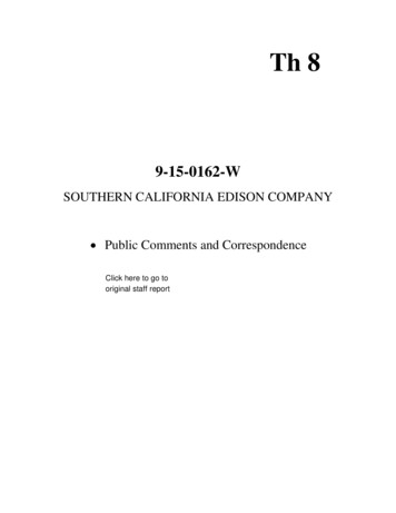
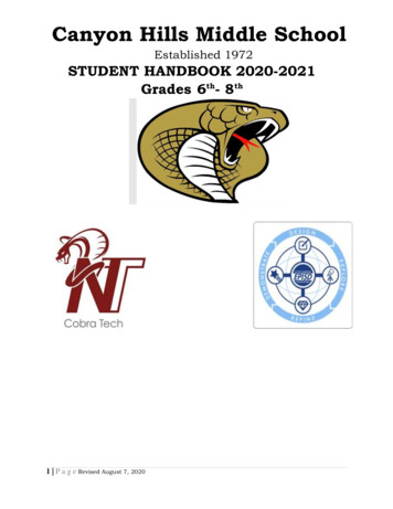
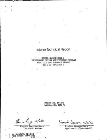
3'IDVP ANALYSIS OF HVAC DUCT AND SUPPORTSDUCX GBHRLE EQ 1duct sample No. 1 consists of oneinch 22 gauge rectangular duct leading fromthe supply fan S-69 to the 4.16kV switchgear room.The duct sample begins at the floor (elevation 119feet) and runs vertically past fan S-69 to a 90degree elbow near the ceiling at elevation 140 feet.The duct then runs horizontally east to the 4.16kVswitchgear room. Figure 1 shows this duct run.The IDVP36 x 16The vertical duct is restrained by twointermediate supports. In addition, the duct at thewall and slab penetrations is riveted to built-inflanges.The horizontal duct is restrained by one threeway support and three sets of vertical rod hangers.This horizontal run is covered with 7/8 inch thickpyrocrete (fire protection). In addition, the ductat both wall penetrations is riveted to built-inflanges.The IDVP developed mathematical models (bothclosed form and computer) of the duct and supportsfrom field verified dimensions (Reference 15).Since the duct is anchored at the walls and slab,the vertical and horizontal runs were analyzedseparately.Zariizal,Duck Buuvertical duct is fixed at the wall mountingfloor mounting. Thus,the vertical duct is isolated from the horizontalduct (Reference 13 and 14). The field verificationThenear the elbow and at theshowedpoint1that angles on three sides of the duct at(Figure 3), which were shown on the drawing/installed (EOI 1110).The vertical duct was modeled as a simplysupported vertical beam with an additionalwere notconcentrated mass located where the portion of ducttees off to fan S-69 through a flexible coupling.This model was used in the frequency analysis of thevertical duct in the East-Nest and North-Southdirections.
R/USED 708u/L7-/A/ PLAA/GEI@OP HAk'6FES7uaez'.WAYSL/rPOA'r/S R/UE78D 70au/Lr-W AweA7SALL 70 /Ou'DL/CfAk'GLES A/074//DWA'8/FIELOCOuCR'Ere BLOCK tVASL. plAle/dr PORrVERl7CALEW77/NEZ WAfgb'PP087/ LE)(lf3LECM'PZ/4'6 /AIPDRCEOCOuCZZfE XLA8EL. // PudC7: COPPER MIR/W oG5R/V ZO 7O84/L7-./u SLAkgEA-8C CASS'NArtES)zz cuaczFigure No.lSample No. 1'uct
O 17Figure No.(Rigid Element)(Rigid Element)2Computer Model Duct Sample No.HorizontalRun161
6 91I451(Concentrated Yiass24.5"Figure No.,3Computer 1Sdel Duct Sample No. 1VerticalRun
intermediate supports for this verticalduct were neglected in the closed form frequencyanalysis. The first natural frequency is in therigid range, th'erefore this approach is conservativewith respect to the resulting accelerations.Because the duct is essentially a column,was assumed to be rigid in the vertical direction.Seismic accelerations were chosen from Hosgriresponse spectra, to correspond to the IDVP naturalfrequency results (see Appendix A).The twoitThe values are asfollows:1.5g Horizontal East-Nest1.5g Horizontal North-South1.5g VerticalAll natural frequencies were in the rigidthe damping value selectedirrelevant. To obtain the acceleration values,range, and therefore,wasseismic response spectra for both elevations 119 and140 feet in the turbine building were enveloped.calculate internal duct loads, an equivalentThese loads were then usedto calculate stresses in the vertical duct using theclosed form solution (simply supported beam with aTostaticmethod was used.concentrated mass).Tocalculate support loads,a STARDYNEcomputermodel was developed (See Figure 3). Loads at eachof, the supports were calculated by applying theacceleration values noted above to this duct model.The vertical duct and supports were represented as aseries of beam elements. The duct attachment at thefloor and at the wall were represented as fixedpoints. The rivets, spaced 8 inches on center,attach to angles which bolt to both the wall andfloor. These connections were considered to befixed. The intermediate supports on the duct weremodeled as a restraint in three directions (for thelower support) and as a restraint in the verticaland'East-Nest directions (for the upper support).Stresses were calculated at key locations in thesupports.
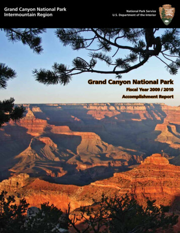
Earizauial DuctEuaA computer STARDYNE model was developed tocompute the duct system frequencies and seismicloads for the horizontal duct run. The duct waswith a series of beam elements runningfixed end points at the walls (see Figure 2).modeledbetweenThe duct was connected by two rig'.d elements tothe centerline attachment point of the three-waysupport. The three-way support, constructed of3 x 3 x 1/4 inch angles,was modeled in detail usinga series of beam elements. The 3/8 inch diameter rodhangers were modeled as vertical springs connectedbetween the ceiling and the duct to account for theirPyrocrete fire proofing material (5 psf)included in the mass properties of the duct(Reference 16).stiffness.wasThe STARDYNE computerall directionsanalysisshowedthat inthe natural frequencies of this ductsystem were greater than 33 hertz. Seismicaccelerations were enveloped from Hosgri responsespectra to correspond to IDVP natural frequencyresults. As with the vertical duct, all naturalfrequencies are in the rigid range and the dampingvalue is irrelevant. Spectra for elevations 119 and140 feet were used to determine the accelerationvalues because the duct system attaches to theelevation 140 feet ceiling slab and the walls below.The seismic acceleration values used in theanalysis of the horizontal duct and supports are asfollows:1.5g Horizontal East-Nest1.5g Horizontal North-South1.5g Verticalhorizontal duct stresses and support loadswith the STARDYNE model. Using these.support loads, stresses at the key locations of thesupport were calculated.Thewere computed10
The IDVP computed stresses at the following keyareas of the duct and duct supports and comparedthem,to the allowable stresses.IDVPBaazLiastressstressDuct column buckling stressDuct local panel bucklingstressllaximum bendingMaximum shearAnchor438.43120970psipsipsipsi24,000 psi14,400 psi20,180 psi150682852126098lblblblblblb24,000 psi14,400 psiboltspull outshearRivet to duct, shearAngle bending stressNeldboltspull outAnchor105shear613280Rivet to duct, shearNeldCapscrews,pullout193197Rivet to duct, shear* Forlocation designations,Vertical 400 psilblband Duct Supportspsi17731273552psipsisee Figure1792Results
llaximum bending andstressMaximum shearaxial821stress340psipsi24,000 psipsipsi24,000 psi14,400 psi14,400 psiBilateral aepauri angl :aHaximum bending stressHaximum shear stress133343boltspulloutAnchorshearGuapari lblbll"l.Capscrevrspulloutshear98Rivet to duct, shear348Tensile stressCompressive stress* For1720344location designations,TableHorizontal Ductpsipsisee Figure57032and Duct Supports1221,600 psiResultspsi
II
calculated stressesfor the key areas are below the allowable stresses.3.1.3 Daaiaa haaLYaia. Hotbed@.The design analysis considered only thebilateral support for the horizontal duct leading toTheresultsshowthatIDVPthe 4.16kV switchgear room.Because the support is located at mid-span ofthe duct, the design analysis considered the totalsupport mass to be half of the total duct mass addedto the support mass structure. This mass along withthe calculated stiffness of the support was used tocalculate the natural frequency of the support( 33 Hz). Based on these natural frequency results,Hosgri accelerations at elevation 140 feet wereselected. These accelerations were used tocalculate loads on the support. Using these loads,loads on the concrete expansion anchors were thencalculated and compared to the allowables.3.1.4 Cnmpaziam af IDLER aaQ Draiaa Bnalxaia. Haihzda.The design analysis examined the expansionanchor bolts to the bilateral support on thehorizontal duct run leading to the 4.16kV switchgearroom. For verification purposes, the IDVP performedThe IDVP analysisa more detailed analysis.examined the duct stresses, support stresses,bolt loads.In addition, stresses in the built-in flangesand the expansionanchorat the attachment points in the wall were alsoexamined.13
The IDVP comparedtheir results listed inSection 3.1.2 with results from the designanalysis that are-shown below:DesignIDVPhaalzaia.hoalxaia.Loadat 16359443Comparison of IDVP and Design Analysis ResultsHVAClbslbsDuct Sample No.1The larger loads calculated in the designanalysis reflect the conservatism in thesimplified design analysis approach.14for
IC
The IDVP issued two EOI reportsAppendix B showsduct sample No.number, revision, date and status.l.for thetheEOIHVACfileEOI 1003 was issued as a result of concernsnoted in the RLCA report "Preliminary Report,Seismic Peverification Program — November 12, 1981"(Reference 2), The concern noted that Hosgri ductsupport qualifications for the 4.16kV switchgearroom ventilation system had not been located as ofOctober 28, 1981. When the analyses of record datedprior to October 28, 1981 were located, the IDVPfound that these calculations did not qualify thethree-way support on the horizontal duct run. Thecurrent design reanalysis (Reference 7) specificallyqualifies the three-way support on the horizontalduct.with 1077 (see Section3.2.6) and classified as a Class A or B Errorbecause the Diablo Canyon Project has stated that(Reference 8).HVAC supports are being reanalyzedEOI 1110 was issued as a result of a differencebetween the field verified condition and the designdrawing. The design drawing calls for angles onthree sides of the duct at point 1 (Figure 3) forThe IDVP field verification doesHVAC sample No.l.thesenot showangles. The IDVP analysis which isbased on the field verified conditions did notinclude the missing angles. This EOI is classifiedas a potential open item with future action byEOI 1003 was combinedPGandE.15
I
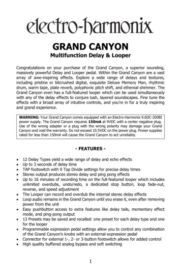
EV6C DUPLE HQ 3 22.sample No. 2 consists of both 12 andNeither of theseduct segments.diameter10 inchducts are covered by fireproofing material.The 12 inch diameter 24 gauge duct which extendsover the primary make-up water pumps at elevation100 feet is in the auxiliary building. This duct iswelded to a built-in flange at one end and restrainedby one bilateral support (vertical and North-South).Figures 4 and 5 show this duct.The straight 10 inch diameter, 24 gauge, ductis also in the auxiliary building at elevation 100feet just south of the HEPA filter rooms and theroughing filter room. This duct is welded tobuilt-in flanges at each of the ends and isrestrained by three sets of 3/8 inch rod hangers.Figure 6 shows this duct.HVAC3 2 1HaihaQaf IMP haalxaia.developed STARDYNE computer models ofinch diameter ducts and supports 'usingfield verified information (Reference 15). Thesecomputer models are shown in Figures 7 and 8.theThe IDVP12 and 10Iat:h Diameter. DuckThe 12 inch diameter duct and bilateral supportwas modeled as a series of beam elements, assuming afixed end at the wall. This model included tworigid links (elements 22 and 23) which connectedthe duct to the support.All the bilateral support members vere representedin the model. The rigid element connection vas modeledThis yielded conservativeas a three-way support.loads on the bilateral support. The resultantfrequencies were greater than 39 Hertz. The IDVPdetermined that this additional direction of restraintwas not significant in the frequency calculation.12.Accelerations were obtained from the elevation115feet Hosgri spectra (Appendix1.23g Horizontal East-West1.05g Horizontal North-South.80g Vertical16A) as shownbelow.
1/CNE'E///Fo cEocokCzZFF sA/C0 A gvY/E-pouSAuavoesC'5XqE'g4AA/5/W/aYAkhEL,09 3X IS A/J@L,ES'ELDER 70BD'/L7-/Al FLAp5E l "ao/rsIC5XP CAA'llkE'LSZZaZr izABovQH/Cr.HoR'LLbsrm7/u P4k'PosdDoh/yWo NoarssFigure Ho.4Duct Sample Ho. 212 Inch Duct
C5x9 2 x23;x 00015IIFigure No.5Duct Sample No. 212 Inch Duct, Support Detail18Typical
ArrA h'EP'eau/uc EGIN/FO/ C EPCN/CZEPZ SALL/4 WELDED PLICA7D Bl/!L7 /A/FLAk5Wr CWCear ggLL.ZEu/mA'CEPLOuCPEreSALLFigure No.6Duct Sample Ho. 210 Inch Duct
Qiogz,/siz l4Zg'zogOt8QnQzrZlzzQ2 S/MYZOk'7ALPLAAIE'3A z4Qqj1i I8 Q,gSoELEMENT(inches10. 00ZOJLENGTH16.7216.7216.7218.0030.005FE DE?A/6ABOVEQ5Q6Figure No.7Computer Yodel Duct Sample No.12 Inch Duct202
234"74 It73"Figure Ho.8Computer Yodel Duct Sample No. 210 Inch Duct21
Since all frequencies were found to be in therange, the damping value used was irrelevant.rigidaccelerations were used to calculate ductsupport loads using the STARDYNEcomputer model. Support stresses were then handcalculated from these loads.ThesestressesandThe straight run of 10 inch diameter duct wasmodel'ed as a series of beam elements assumingfixed-end connections at the walls. This model isshown in Figure 8. Rod hanger supports were modeledas springs to account for stiffness.Accelerations were obtained from the elevation115feet Hosgri spectra (Appendix1.20g Horizontal East-Nest1.16g Horizontal North-South0.60g VerticalA) as shownbelow:Since all frequencies were found to be in therigid range the damping value used was irrelevant.These accelerations were used along with thecomputer model to calculate duct stresses andsupport loads. Support stresses were then handcalculated from these loads.22
The IDVP compared the calculated stresses forduct sample No. 2 to the allowable stresses.These comparisons are presented in Tables .4 and 5.HVAC23
k
IDVPAnalysisECQQgi:s!lax-'mum bending andstressllaximum shearaxialpsipsi24,000 psipsipsi24,000 psii24,000 psi558psi14,400 psi1495psi14,400 ppilblblblblb13,700 lb1063stress258C5x9 ChannelHaximum bendingstress(at node 9)Haximum shear stress(at node 12)2-1/2 x 2-1/2 x 1/4 inchQ].],o gggR1111147014,400 psi14,400 psiAnglellaximum bending stress(at node 21)1617 psstress(at node ll)Naximum shearEziui3.*Weld maximum shearstressReiver 6*Bolt shear937937Bearing937832Channel bearingAngleSheartearout stressAnchor bolt(combined pullout and shear5245tearout stresslocation designations,Table121.0lb413,700 lb14,400 psipsisee FigureInch Duct Results2414,400 psi0.21Bearing* Forpsiinteraction)Angle (at wall)Shear3,34011,4007
IDVPBa.a.alia.Rciai 1ZBolt shear970Channel bearingAngle.970BearingShear tearout stressAnchor bolt(combined pullout and shear9708620.23BearingRaisinpsilblb13 i 700 lb14,400 psi3,34011,4001.0interaction)Angle (at wall)Shearlblblb6548tearout stresslbpsii 11014,4009lbpsi12. 13. 3.R 29.(Norst case reported)BoltTensileill lblb115ShearAngleBearingShearPapula.111170tearout stressll 14lblblb9gllO lb6,6803g340psi14,400 psilblblb6i680 lb3,340 lb(worst case 0tearout stresspsi9,110 lb.14,400 psiRaiaia 12 21(worst case hear 'tearout stressMeld shear'tressDuct strapNaximumtensile stress49gllO lb9,797 psipsi24,000 psiinch Duct Results (cont.)256i680 lb3i340 lb14,400 lb14,400 psi4859Table12lblblblb
l1aximum bending stressMaximum shear stress57270psipsi24,000 psi14,400 psi839psi14,400 psi143psi21,600 psi9,700 psi24,000 psi14,400 psiSuapari Eainia. 1 aaQ R"(worst case reported)Weld shearstressEa.C Ha.aber.r.(worst case reported)Tensile stressDuck Shrankstressshear stressllaximum bendingHaximum202Table10psi5Inch Duct Results*For location designationssee Figure268
Following the IDVP sample selection, a designanalysis was performed (Reference 9) whichconsidered the bilateral support for the 12 inchdiameter duct over the primary make-up water pumps.A'osgri qualification analysis for the bilateralsupport dated prior to the selection of this HVACsample could not be provided (EOI 1077). Thenatural frequency of the support in the verticaldirection was calculated by hand. Seismic loads onthe support were analyzed in both the vertical andhorizontal directions. The design analysis examinedonly the stresses in the support channel.The 10 inch diameter duct is supported by rodhangers and built-in flanges. Design analyses wereonly performed for multidirectional seismic supports,not for rod hangers and built-in flanges.3.2.4 ggggj.egg gf QVp, gag Qggj.gg Qgg gj.g Qgfgojg.Different methods were used in the IDVP anddesign analysis to calculate the naturalfrequencies. The design analysis used handcalculations, while tne IDVP analysis used acomputer model to derive natural frequencies and tocalculate loads and forces at the key locations.The design analysis considered only support stresseswhile the IDVP analysis examined both the duct andthe supports. The IDVP analysis examined thesupports in detail, and in particular calculatedstresses considering local effects.The stresses calculated in the design analysisfor the support channel are much higher than thosedetermined in the IDVP analysis because the designanalysis used a simplified and conservativeapproach.27
3.2.5Cumaariazu Zf IDYL and. Daaiaa.hualxaiaEeaz3.fa.The IDVP comparedtheir results listed in.Section 3.2.2 with results from the design analysisas shown below:IDVPhaalzaia.channelbending tensile stressC5X9121.11 ksiDesignhaply.cia.16.9 ksiInch Duct ComparisonTable6higher stresses calculated in the design analysisTotal duct and support weight was considered inapproach.the design analysis to act at the midspan of a simplysupported channel. By contrast, the verification analysisconsidered portions of duct and support weight to act atthe built-in flanges and distributed the channel weight overThereflect the conservatism in the simplified design analysisapartially fixedend beam.28
The IDVP issuedsample No. 2.revision, date,one EOI report for HVACB shows the EOI number,AppendixandEOI 1077 wasstatus.issued because the Hosgriqualification calculation for the duct support forduct sample No. 2 is dated November 8, 1981. Acalculation dated pri'or to November 8, 1981 (Hosgrire-evaluation) could not be located. Therefore aconcern was raised as to whether this duct supportwas reviewed for the Hosgri.EOI 1077 was combined with EOI 1003 as an ClassA or B Error.29
4.0,EVALUATION4.1ZHTERREKTGTXQHThe IDVP performed analyses for two samples ofI HVAC duct and supports. The resultswere compared to the allowables and design results.All stresses were found to be below the allowables.design ClassThree EOIs have been issued as a result of thecomparison of IDVP and design analysis results (1003,1077 and 1110).The IDVP notes a concern based onEOIs 1003 and 1077 that certain HVAC supports maynot have been evaluated for Hosgri loadings. EOI1110 notes a difference between the drawings andas-built conditions and has yet to be resolved.The design analyses are based on the use ofrules. The IDVP used closed form solutions andspanThiscomputer models to analyze the HVAC samples.approach was taken in the absence of a documentedHVAC duct and support design methodology.However,the IDVP accepts the use of documented span rulesfor the designsupports.4.2andanalysis ofHVACduct andRECQHHEHMTIQHRThe following recommendationsconcerns described above.oaddresstheto verifyduct andsupports are evaluated for Hosgri loadings.Establishand implement a programthat all design Class IHVACto evaluatesupports.The DCP has established an Internal TechnicalProgram to address these concerns for the designClass I HVAC duct and supports.For each of therecommendations, the IDVP will selectively verifythe corrective action PGandE implements.oDocument a design methodologydesign Class I HVAC duct and30
I
5'CONCLUSIONThe IDVP performed verification analyses for twoHVAC duct and supports.All stresses werefound to be below the allowables. As a result of thesamples ofcomparison with the design analyses,been noted."ootwo concernshaveIn certain cases, design Class I HVAC ductsupports were not evaluated for Hosgri loadingsA design methodology for evaluation of HVAC ductsand supports has not been documented.The DCP hasinitiated corrective actions tothese two concerns.the IDVP.Theseactions31will beaddressreviewed by
6.0REFERENCES1.'2 Independent DesignDCNPPVerificationProgram,Plan, Phase I, Revis'ion 1,July 6, 1982 (Revision 0, Narch 29, 1982).Program NanagementPreliminary Report, Seismic ReverificationProgram, Robert L. Cloud Associates,,November12'981.3 Diablo Canyon Site Units 1 and 2 "Final SafetyAnalysis Report," USAEC Docket Nos. 50-275 and50-323. RLCA File No. P 105-4-200-005.4 Seismic Evaluation for Postulated 7.5 H HosgriEarthquake, USNRC Docket Nos. 50-275 and50-323. RLCA File No. P105-4-200-001.5.DCNPPIndependent Design Verification Program,Program Procedure, Phase I Engineering ProgramPlan, Revision 0, liarch 31, 1982. RLCA FileNo. P105-4-810-021.6.Spec. No. 8827, Specification for FurnishingInstalling of. Design Class —I Heating andVentilation Systems for Unit 1 Diablo CanyonSite. RLCA File No. P105-4-436-002.PGandEand7 EOI 1003RLCA8.9.10.Fileresolution material,No. P105-4-1003-008.PGandEI FinalReport, September 17, 1982.PGandE calculations, supplied for RLCA Requestfor Information No. 88. RLCA File No. P105-4-436-007.PGandE PhaseURS/ J.A. Blume Report, Turbine Building Evaluationand Structural flodifications for the 7.5 l1 HosgriEarthquake, llarch 1980. RLCA File No. P105-4-441-032.RLCA HVAC Rectangular Duct Analysis,RLCANo. P105-4-560-001.File12.13.RLCA HVAC Round Duct Analysis,RLCANo. P105-4-560-006.FileRevsion 2.Revision 2."Ventilation Plans and Sections AreaElevation 75'3" through 119'0"", 59322, Revision 17.PGandE Drawing "Ventilation D
3 ' IDVP ANALYSIS OF HVAC DUCT AND SUPPORTS DUCX GBHRLE EQ 1 The IDVP duct sample No. 1 consists of one 36 x 16 inch 22 gauge rectangular duct leading from the supply fan S-69 to the 4.16kV switchgear room. The duct sample begins at the floor (elevation 119 feet) and runs vertically past fan S-69 to a 90 degree elbow near the ceiling at elevation 140 feet. The duct then runs horizontally east .