Transcription
BACK TO BASICS: DUCT DESIGNMatthew Low, M.AIRAH, CPEng15 MAY 2013
Back to Basics: Duct Design Quick Introduction Duct Sizing Tools and Methods Recommended Duct Velocities and Noise Effects Duct Fitting Pressure Losses Do and Don’ts of Duct Design Duct Applications AS 4254
Quick IntroductionA “Good” Duct Design is a Balance between Application (Design Intent) Reliability (Maintenance Cost) Manufacturing Costs (Capital Cost) Pressure Loss (Operational and Energy Cost) Acoustics (Environmental Cost) Air Balancing (Commissioning Cost)
Duct Sizing ToolsORDuct Sizing ChartAIRAH DA3 Duct Design ManualDuctulator (Manual/Digital)Manufacturers/Programs
Duct Sizing MethodsMethodsDescription SummaryVelocityReduction Base on ExperienceQ VA (Continuity equation) Simplest Not standardNot completely balancedConstantPressureGradient Also called Equal FrictionIn Pa/m Straight ductHigher Pa/m used Very Simple Considerable dampeningrequiredStatic Regain Supply air onlyDecrease in velocity pressurebranch or fittingOffsets friction loss insucceeding section of ductFixing 1st Segment withmethods above Lower systempressure lossLower EnergyconsumptionLess Noise issues intake offs Larger duct sizesIncreased capital costIncreased spatial requirementsAny method above initiallyDetermine the index runResize to ensure pressureloss similar to index Better pressurebalanced systemSmall duct sizesReduced capital andspatial costs Tedious CalculationsHigher velocities at take offsmay be noisyDampering of Larger ducts maybe as or more noisyASHRAE FundamentalsOperation and Capital Costoptimisation focused SimpleBest EconomicalSizing Method BalancedPressure DropT-Optimisation Pros Cons Very tedious calculations withsimulationsSpatial costs neglected
Recommended Duct Velocities and NoiseEffects Table above shows the duct velocities based on AES projectexperience HOWEVER, Project/Design Engineer must always check andselect appropriate sizes to suit the project’s complexity andapplication
Duct Fitting Pressure Loss Various duct fitting pressure lossesAIRAH DA3 or the AIRAH Technical HandbookMore available in the ASHRAE Handbook or SMACNAObtain other duct fittings pressure losses from manufacturerssuch as duct heaters, dampers, filters, grilles, coils, etc Calculated by the following formula (derived from Bernoulli’s) PTOTAL KT X PV KT X ½ X ρV2 PTOTAL the total pressure loss across the duct fittingKT the pressure loss coefficient of duct fittingPv velocity pressure (dynamic pressure)ρ density of airV velocity of fluid
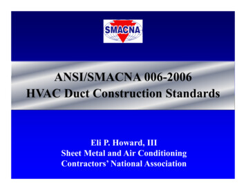
Example of Duct Fitting LossVu Upstream velocity offittingH Height of the ductW Width of the ductR Radius of the bendΘ Angle of the radiusCalculate the pressure loss of the duct fitting in a 600mm W x200mm H duct with a radius of 600mm and a 90 Bend angle. SayReynolds number as 4500. Therefore the pressure loss is 0.2149
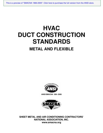
Example of an AES Static Calculation Sheet Can be summarised in aspreadsheet Remember to include othermanufacturer’s type ancillary ductfittings like duct heaters, VAVs,coils, etc Total static pressure safetyvarious on application
Installation Do’s and Don’ts Good resource - “Fans by Fantech Book”
Installation Do’s and Don’ts by Fantech
Duct Applications Kitchen Exhaust Ductwork Smoke Exhaust Ductwork Seismic Restraining Winds Restraining (not covered in this presentation) Acoustics and Attenuation (refer to Back to Basics: Acousticsheld last Technical Meeting) Etc
Kitchen Exhaust Ductwork Construction of 1.2mm or 0.9 stainless as perAS1668 standard with Seams sealed to preventgrease leakage. Spigot connections at 5 to 7m/s. Duct to slopeup in direction of flow for grease flow back tohood. Duct access panels every 3 metres of straightduct and change of direction. Builder/Architectmust provide access panels. Lower edge of canopy type must not be lessthan 2m above floor level at the operator side ofcooking equipment.
Smoke Exhaust Ductwork Internal insulated smoke exhaust ductworkmust have perforated metal lining Coated with fire rated spraying/wrapping,cladding and etc must applied where smokeexhaust ductwork in a different firecompartment it serves Construction of 1.2mm galvanised steel or0.9mm stainless steel thick ductwork.Subducts are 2mm ductwork and fullywelded at each level to prevent smokemigration between non fire affected floors.Riser shafts adequately sized to allow forrestrictions.
Seismic Restraints Requirements determined by AS 1170.4-2007and not clear in design documents. Building Structural Engineer and BuildingCertifier to classify the following:– Earthquake Design Category– Building Importance– Probability of Exceedance of design eventsand Probability factor– Hazard Factor– Site Sub Soil Classification Duct installed to be reviewed initially and finallyby structural engineer (project or independent)prior to completion
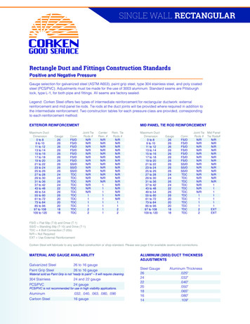
AS4254: Duct Classification Standard Duct pressure classification tables found in the AS 4254 such as low,medium or high pressure AS4254 explains duct thicknesses, sealing, reinforcement andfunctional requirements. Refer to table 2.3 for duct thicknesses andreinforcement methods Changes to 2012 edition as follows: Fire rated duct must be constructed to the same standard as the testedsolution for that particular product. Detail must be obtained from therelevant supplier at the start of the project and may be differentdepending on the proposed fire rating method. Any duct system over 3000 L/s must be tested at minimum 10% ofeach system at 1.25 times operating pressure.
Thank You
BACK TO BASICS: DUCT DESIGN . Back to Basics: Duct Design Quick Introduction Duct Sizing Tools and Methods Recommended Duct Velocities and Noise Effects Duct Fitting Pressure Losses Do and Don’ts of Duct Design Duct Applications AS 4254 . Quick Introduction A “Good” Duct Design is a Balance between Application (Design Intent) Reliability (Maintenance Cost .