Transcription
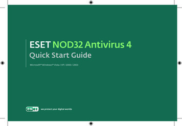
Quick Start GuideFASTHUB 400 10/100 SERIESCABLING AND START UPSERIES1TAKE OUT WHAT YOU NEED2CONNECT THE HUB TO OTHER NETWORK DEVICES3ASSIGN IP INFORMATION TO THE HUB4DISPLAY THE WEB-BASED HUB MANAGER
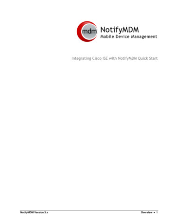
Take Out What You NeedFastHub 400 10/100 series hub(12- or 24-port model)10BaseT/100BaseTx10BaseT/100BaseTxRPS10 1001xRPS2x3x4x5x6x7x8x9x10x11x10 18x19x20x21x22x23x24x24ntio onla tial rast gu eIn nfi uidoC GrttaSck deui uiQ GFastHub 400 10/100 Series Installationand Configuration Guide1x12MODERJ-45-to-RJ-45 rollover console cable(FastHub 412M and FastHub 424Mmodels only)1RJ-45-to-DB-9 console-to-PC adapter(FastHub 412M and FastHub 424Mmodels only)Black AC power cableRack-mount kitRubber feetIf any item is missing or damaged, contact your Cisco representative or reseller for support.Note: You need to supply Category 3, 4, or 5 straight-through or crossover cables to connectto Ethernet devices.
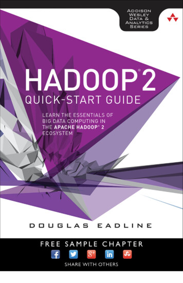
Connect the Hub to Other Network Devices10BaseT/100BaseTxRPS10 8x19x20x21x22x23x24x2410BaseT/100BaseTXnetwork port (RJ-45)Maximum cable length:328 ft (100 m)10BaseT or100BaseTX port(RJ-45)Ethernet cable(not supplied)2Note: Use a straight-through cable toconnect two ports when one of the ports isdesignated with an X. Use a crossover cableto connect two ports when both ports areConnect the Hub to Switchesand Other Hubs Connect a Category 3, 4, or 5 crossovercable to any 10/100 port on the hub andto a 10BaseT port on the target switchor hub. Connect a Category 5 crossover cable toany 10/100 port on the hub and to a100BaseTX port on the target switch orhub.designated with an X.Connect the Hub to Servers,Routers, and Workstations Connect a Category 3, 4, or 5straight-through cable to any 10/100port on the hub and to a 10BaseT porton the workstation, server, or router. Connect a Category 5 straight-throughcable to any 10/100 port on the hub andto a 100BaseTX port on theworkstation, server, or router.
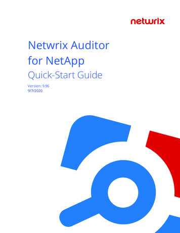
Connect the Hub to Other Network Devices(continued)RATING100-127 / 200-240 V 2A /1A 50 / 60 HzCONSOLEUPDC INPUTS FOR REMOTEPOWER SUPPLYSPECIFIED IN MANUAL 5V @6A, 12V @1ADC INPUT10/100 BASE-TXDOWNMEDIA MODULESTAT DUP 100RATING100-127 / 200-240 V 2A /1A 50 / 60 HzCONSOLEUPDC INPUTS FOR REMOTEPOWER SUPPLYSPECIFIED IN MANUAL 5V @6A, 12V @1ADC INPUT10/100 BASE-TXSTAT DUP 100DOWNMEDIA MODULERATING100-127 / 200-240 V 2A /1A 50 / 60 HzCONSOLEUPDC INPUTS FOR REMOTEPOWER SUPPLYSPECIFIED IN MANUAL 5V @6A, 12V @1ADC INPUT100 BASE-FXLINK DUPTXRXDOWNMEDIA MODULE3(Optional) Install theSwitched Uplink Module inthe Hub12Power off the hub.Remove and set aside the screwsattaching the faceplate to expansion sloton the hub. The screws will be used laterin Step 6.3Remove the faceplate from the hub andstore it for future use.4Slide the module into the slotcard-guides until you feel it touch theback of the hub.5Push the module firmly until it snapsinto place and is firmly seated.6Insert and tighten the screws on themodule faceplate.7Power on the hub.(Optional) Connect to theSwitched Uplink ModulePortInsert a connector according to the type ofmodule (10/100 or 100BaseFX), as follows: 10BaseT/100BaseTX connector—Insertthe connector until it snaps into place in themodule port.Note: Use a straight-through cable toconnect two ports when one of the ports isdesignated with an X. Use a crossover cableto connect two ports when both ports aredesignated with an X. 100BaseFX SC connector—Remove therubber plugs from the fiber-optic porton the module and store them for futureuse. Insert the connector in thefiber-optic module port.
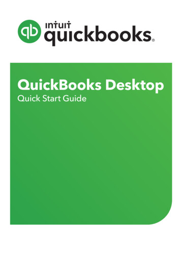
Connect the Hub to Other Network Devices(continued)RATING100-127 / 200-240 V 2A /1A 50 / 60 HzCONSOLEDC INPUTS FOR REMOTEPOWER SUPPLYSPECIFIED IN MANUAL 5V @6A, 12V @1AUPDC INPUT10/100 BASE-TXSTAT DUP 100DOWNMEDIA MODULEConsole port(RJ-45)Power outletRJ-45-to-RJ-45rollover console cable(supplied)RJ-45-to-DB-9adapter (supplied)(Optional) Connect theConsole Cable1Make sure console port settings of theFastHub 400M model match thesettings of the terminal, PC, or laptop.The default settings of the hub consoleport are 9600 baud, 8 data bits,1 stop bit, no parity, and no flowcontrol.Power Up the Hub1Connect one end of the power cord tothe hub and the other end to a powersource.Note: You can use the internal powersupply and the Cisco 600W AC RedundantPower System (RPS). Attach only the CiscoRPS (model PWR600-AC-RPS) to the RPS2Connect the rollover console cable tothe CONSOLE port on the hub.receptacle.3Connect the other end of the rollovercable to your terminal, PC, or laptop(if necessary, use an appropriateadapter, such as the suppliedRJ-45-to-DB-9 adapter).24From your terminal, PC, or laptop, startthe terminal emulation program.Wait approximately 2 minutes for thehub to complete its power-on self-test(POST).After POST completes, the Continuewith configuration dialog? promptappears on the management station.You can then follow the prompts toassign IP information to the hub.4
(Optional) Assign IP Information to the HubThe hub is designed to operate with little orno user intervention. In most cases, you canuse it with its default settings.Assign IP information to the FastHub 400Mmodel so that you can use the FastHub 400series Hub Manager web-based interfaceand so that the hub can communicate withlocal routers and the intranet.Contact your system administrator for thehub IP information, and record it here.Hub IP address:4Enter the IP address of the defaultgateway (for example: 10.1.105.254):Enter IP default gateway: 10.1.105.254The following information is displayed:The following configuration commandscript was created:ip address 10.1.105.20 255.255.255.0ip default-gateway 10.1.105.254!end5Enter Y:Use this configuration? YSubnet mask:The following information is displayed:Default gateway:51From the terminal or PC, enter Y:Continue with configuration dialog? Y2Enter the IP address (for example:10.1.105.20):Enter IP address: 10.1.105.203Enter the subnet mask (IP netmask)(for example: 255.255.255.0):Enter IP netmask: 255.255.255.0Building configuration.Use the enabled mode ‘configuration’command to modify this configuration.Press RETURN to get started.67Press Return.Exit from the terminal session.You can now display the FastHub 400 seriesHub Manager.
(Optional) Display the FastHub 400 SeriesHub ManagerIf you have the IP address to the hub, you can display the FastHub 400 series Hub Managerfrom your intranet. You can use the FastHub 400 series Hub Manager to configure and monitorthe hub.1Start Netscape Communicator (4.03 or higher) or Microsoft Internet Explorer(4.01 or higher). Make sure that Java and JavaScript are enabled.2Enter the IP address of the hub in the URL field if you are using Communicator(the Address field if you are using Internet Explorer).The FastHub 400 series Hub Manager Home page appears.Click Apply aftermaking changeson a page.Click Revertto discardunappliedchanges ona page.HOMEPORT GROUP IP SNMP CDP SYSTEMClick these topics to move from pageto page. On Netscape Communicatoronly, when the cursor is above a topic,a pop-up briefly describes the optionson that particular page.Click a port to display itssettings, status, and statistics.Click Help forprocedures anddetailed fielddescriptions.Click the Modebutton to changethe mode thatthe LEDs displayfor the fixed10/100 ports.Click to display the settings, status, andstatistics of an installed 10BaseT/100BaseTXor 100BaseFX switched uplink module.Shows when another hub is connected to astacking connector on the hub rear panel.Note: The FastHub 400 10/100 Series Installation and Configuration Guide and theFastHub 400 10/100 series Hub Manager online help provide complete information about theweb console and describe how to configure and monitor the hub.6
Corporate HeadquartersCisco Systems, Inc.170 West Tasman DriveSan Jose, CA 95134-1706USAhttp://www.cisco.comTel: 408 526-4000800 553-NETS (6387)Fax: 408 526-4100European HeadquartersCisco Systems Europe s.a.r.l.Parc Evolic, Batiment L1/L216 Avenue du QuebecVillebon, BP 70691961 Courtaboeuf CedexFrancehttp://www-europe.cisco.comTel: 33 1 6918 61 00Fax: 33 1 6928 83 26AmericasHeadquartersCisco Systems, Inc.170 West Tasman DriveSan Jose, CA 95134-1706USAhttp://www.cisco.comTel: 408 526-7660Fax: 408 527-0883Asia HeadquartersNihon Cisco Systems K.K.Fuji Building, 9th Floor3-2-3 MarunouchiChiyoda-ku, Tokyo 100Japanhttp://www.cisco.comTel: 81 3 5219 6250Fax: 81 3 5219 6001Cisco Systems has more than 200 offices in the following countries. Addresses, phone numbers, and fax numbers are listed on theCisco Connection Online Web site at http://www.cisco.com.Argentina EnglandFranceMexico Australia AustriaGermanyThe NetherlandsSouth Africa Spain BelgiumGreece Brazil Canada Hungary IndiaIndonesia New ZealandSweden NorwaySwitzerland Peru Chile China (PRC) PhilippinesTaiwan, ROC Ireland Thailand Poland ColombiaIsrael ItalyPortugalTurkey Costa RicaJapanRussia KoreaCzech Republic Luxembourg Saudi ArabiaUnited Arab Emirates ScotlandUnited States DenmarkMalaysiaSingaporeVenezuelaAccessPath, Any to Any, AtmDirector, the CCIE logo, CD-PAC, Centri, the Cisco Capital logo, CiscoLink, the Cisco Management Connection logo, the Cisco NetWorks logo, theCisco Powered Network logo, the Cisco Press logo, the Cisco Technologies logo, ClickStart, ControlStream, DAGAZ, Fast Step, FireRunner, IGX, IOS, JumpStart, Kernel Proxy,LoopRunner, MGX, Natural Network Viewer, NetRanger, NetRanger Director, NetRanger Sensor, NetSonar, Packet, PIX, Point and Click Internetworking, Policy Builder, Precept,RouteStream, Secure Script, SMARTnet, SpeedRunner, Stratm, StreamView, The Cell, TrafficDirector, TransPath, ViewRunner, VirtualStream, VlanDirector, Workgroup Director, andWorkgroup Stack are trademarks; Changing the Way We Work, Live, Play, and Learn, Empowering the Internet Generation, The Internet Economy, and The New Internet Economyare service marks; and BPX, Catalyst, Cisco, Cisco IOS, the Cisco IOS logo, Cisco Systems, the Cisco Systems logo, Enterprise/Solver, EtherChannel, FastHub, ForeSight,FragmentFree, IP/TV, IPX, LightStream, LightSwitch, MICA, Phase/IP, StrataSphere, StrataView Plus, and SwitchProbe are registered trademarks of Cisco Systems, Inc. in the U.S. andcertain other countries. All other trademarks mentioned in this document are the property of their respective owners. (9811R)78-5566-01
Connect the Hub to Servers, Routers, and Workstations Connect a Category 3, 4, or 5 straight-through cable to any 10/100 port on the hub and to a 10BaseT port on the workstation, server, or router. † Connect a Category 5 straight-through cable to any 10/100 port on the hub and to a 100BaseTX port on the workstation, server, or router. Connect the Hub to Switches and Other Hubs .