Transcription
USER'S GUIDEVaisala CeilometerCL51M210801EN-A
PUBLISHED BYVaisala OyjP.O. Box 26FI-00421 HelsinkiFinlandPhone (int.): 358 9 8949 1Fax: 358 9 8949 2227Visit our Internet pages at http://www.vaisala.com/ Vaisala 2010No part of this manual may be reproduced in any form or by any means, electronic ormechanical (including photocopying), nor may its contents be communicated to a thirdparty without prior written permission of the copyright holder.The contents are subject to change without prior notice.Please observe that this manual does not create any legally binding obligations forVaisala towards the customer or end user. All legally binding commitments andagreements are included exclusively in the applicable supply contract or Conditions ofSale.N17728
Table of ContentsCHAPTER 1GENERAL INFORMATION. 9About This Manual . 9Version Information . 9Related Manuals . 9Contents of This Manual . 10Abbreviations and Acronyms . 10General Safety Considerations. 11Product Related Safety Precautions . 11Terms Used in Groundings . 13Laser Safety . 13ESD Protection . 15Recycling . 16Regulatory Compliances . 16License Agreement . 16Warranty. 17CHAPTER 2PRODUCT OVERVIEW. 19Introduction to Vaisala Ceilometer CL51 . 19Product Nomenclature. 21CHAPTER 3INSTALLATION. 23Preparing Foundation . 23Creating New Concrete Foundation. 25Using Existing Concrete Foundation. 25Grounding. 25Unloading and Unpacking Instructions . 26Mounting of Ceilometer CL51 . 27Using Tilt Feature . 29Tilting Ceilometer . 29Mounting Optional Bird Deterrent . 30Startup . 32Assembling Battery . 32Connecting External Cables. 34Power Supply Connection. 35Data Line Connection . 35Data Line Modem Connection . 36Data Line RS-485 Connection . 37Data Line RS-232 Connection . 38Maintenance Terminal Connection . 38Setting up Maintenance Terminal Connection. 38Operation of Maintenance Terminal Connection . 39VAISALA 1
USER'S GUIDEStartup Procedure .39Settings for Normal Operation .41Factory Settings of User Programmable Parameters .42CHAPTER 4FUNCTIONAL DESCRIPTION .43Theory of Operation .43Basic Operating Principle .43Practical Measurement Signal.43Noise Cancellation.44Return Signal Strength .45Height Normalization .45Backscatter Coefficient.46Vertical Visibility.47Sky Condition Algorithm .48General.48Option Code .48Activation .48Algorithm Overview .49CHAPTER 5OPERATION.53Operation Modes .53Serial Lines - Open and Closed Port .53User Commands .55Data Messages.60CL51 Data Messages No. 1 and 2 .60CRC16 Checksum.66CL31 Data Messages No. 1 and 2 .67CL51 Status Message .68LD40 Standard Telegram .72Telegram Structure Remarks .73Failure and Warning Messages .73Checksum Calculation.75Manual Message .76Polling Mode .77CHAPTER 6MAINTENANCE.79Periodic Maintenance.79Alarms and Warnings .79Cleaning .80Window Contamination Measurement Calibration.80Checking Door Gasket .81Checking Battery .81Storage .81CHAPTER 7TROUBLESHOOTING.83Troubleshooting Procedure .83Accessing Diagnostic Information .84Equipment for Troubleshooting .842 M210801EN-A
Troubleshooting Instructions . 84Warning and Alarm Messages . 87Technical Support . 90CHAPTER 8REPAIR . 91Replacing Window CLW511 . 93Replacing Ceilometer Laser Transmitter CLT521. 95Replacing Ceilometer Receiver CLR321 . 97Replacing Ceilometer Engine Board CLE321. 99Replacing No-break Battery 4592 . 101Replacing AC Power Supply CLP311. 103Replacing Window Blower CLB311. 105Replacing Internal Heater CLH311 . 107Replacing Laser Monitor Board CLM311 . 109Replacing Modem Module DMX501 (Optional). 110CHAPTER 9TECHNICAL DATA . 113Specifications . 113Mechanical Specifications. 113External Connector J1 - Window Conditioner . 113External Connector J2 - Power Input . 114Output Interface . 114External Connector J3 - Data Line. 114External Connector J4 - Maintenance Line. 116Modem Module DMX501 . 117Transmitter Specifications. 117Receiver Specifications. 117Optical System Specifications. 118Performance Specifications . 118Environmental Conditions Specifications. 118INDEX . 119VAISALA 3
USER'S GUIDEThis page intentionally left blank.4 M210801EN-A
List of FiguresFigure 1Figure 2Figure 3Figure 4Figure 5Figure 6Figure 7Figure 8Figure 9Figure 10Figure 11Figure 12Figure 13Figure 14Figure 15Figure 16Figure 17Figure 18Figure 19Figure 20Figure 21Figure 22Figure 23Figure 24Figure 25Figure 26Figure 27Figure 28Figure 29Figure 30Figure 31Figure 32Figure 33Figure 34Location of Laser Aperture on Ceilometer CL51. 14Vaisala Ceilometer CL51. 20Ceilometer CL51 Measurement Unit Main Parts . 22Foundation Construction . 24Measurement Unit Handle. 26Removing and Attaching the Measurement Unit . 27Mounting the Shield. 28Tilting the Ceilometer . 29Ceilometer CL51 Bird Deterrent. 31Assembling the Battery . 32External Connectors (Bottom View) . 34Data Line Modem Connection. 36Data Line RS-485 Connection . 37Data Line RS-232 Connection . 38Ceilometer Engine Board CLE321 . 40CL51 Switches . 41Typical Measurement Signal . 44Basic Operation of CL51 Sky Condition Algorithm ina 2D Time-Height Domain. 49Control Flow of Sky Condition Algorithm. 51Operation Modes. 53Open and Closed Port. 54CL51 Maintenance Parts. 92Window CLW511. 94Laser Transmitter CLT521 . 95Receiver CLR321 . 97Ceilometer Engine Board CLE321 . 99No-break Battery 4592 . 101AC Power Supply CLP311 . 103Window Blower CLB311-115 / CLB311-230 . 106Internal Heater CLH311-115 / CLH311-230. 107Laser Monitor Board CLM311 . 109Modem Module DMX501. 110DMX501. 111Pin Connections of Connector J4. 116VAISALA 5
USER'S GUIDEThis page intentionally left blank.6 M210801EN-A
List of TablesTable 1Table 2Table 3Table 4Table 5Table 6Table 7Table 8Table 9Table 10Table 11Table 12Table 13Table 14Table 15Table 16Table 17Table 18Table 19Table 20Table 21Table 22Table 23Table 24Table 25Table 26Table 27Table 28Table 29Table 30Table 31Table 32Table 33Table 34Table 35Table 36Manual Revisions . 9Related Manuals . 9Specifications for the Grounding Terms. 13Vaisala Ceilometer CL51 Main Parts . 21Vaisala Ceilometer CL51 Optional Parts. 21Factory Defaults of User-Programmable Parameters. 42Sky Cover Values from the Sky Condition Algorithm. 50User Level Commands. 55Advanced Level Commands . 58CL51 Data messages No. 1 and 2 . 61Messages with 10 m Resolution (Standard Mode) . 67Messages with 5 m Resolution (High Resolution) . 67Error Group Definition . 73Error Group 1 (Byte 83). 74Error Group 2 (Byte 84). 74Error Group 3 (Byte 85). 74Error Group 4 (Byte 86). 74Error Group 5 (Byte 87). 75Error Group 6 (Byte 88). 75Error Group 7 (Byte 89). 75Command Telegram Description 'Polling Request'. 78CL51 Status, Warnings . 87CL51 Status, Alarms . 88CL51 Status, Miscellaneous Problems . 89Available Spare Parts. 91Ceilometer CL51 Mechanical Specifications. 113Window Conditioner . 113Power Input . 114Data Line . 115Maintenance Line . 116Modem Module DMX501 Specifications . 117Transmitter Specifications . 117Receiver Specifications . 117Optical System Specifications. 118Performance Specifications. 118Environmental Conditions Specifications . 118VAISALA 7
USER'S GUIDEThis page intentionally left blank.8 M210801EN-A
Chapter 1 General InformationCHAPTER 1GENERAL INFORMATIONThis chapter provides general notes for the manual and the product.About This ManualThis manual provides information for installing, operating, andmaintaining the Vaisala Ceilometer CL51.Version InformationTable 1Manual CodeM210801EN-AManual RevisionsDescriptionJanuary 2010 - This manualRelated ManualsTable 2Manual CodeM210310EN-AM210717EN-BRelated ManualsManual NameTermination Box User's GuideCL-VIEW User's GuideVAISALA 9
USER'S GUIDEContents of This ManualThis manual consists of the following chapters:- Chapter 1, General Information, provides general notes for the manualand the product.- Chapter 2, Product Overview, introduces the features, advantages, andthe product nomenclature.- Chapter 3, Installation, provides information that is intended to helpwith installing the product.- Chapter 4, Functional Description, provides information on themeasurement principles of the product.- Chapter 5, Operation, contains information that is needed to operatethis product.- Chapter 6, Maintenance, provides information that is needed in basicmaintenance of the product.- Chapter 7, Troubleshooting, describes common problems, theirprobable causes and remedies, and provides contact information fortechnical support.- Chapter 8, Repair, provides information on how to remove and replacedifferent parts of the product.- Chapter 9, Technical Data, provides the technical data of the product.- INDEXAbbreviations and criptionElectrostatic DischargeLight Emitting DiodeLight detection and rangingMeteorological Optical RangeVertical visibilityWorld Meteorological Organization10 M210801EN-A
Chapter 1 General InformationGeneral Safety ConsiderationsThroughout the manual, important safety considerations are highlightedas follows:WARNINGWarning alerts you to a serious hazard. If you do not read and followinstructions very carefully at this point, there is a risk of injury or evendeath.CAUTIONCaution warns you of a potential hazard. If you do not read and followinstructions carefully at this point, the product could be damaged orimportant data could be lost.NOTENote highlights important information on using the product.WARNINGFailure to comply with these precautions or with specific warningselsewhere in this manual violates safety standards of design,manufacture, and intended use of the instrument. Vaisala Oyj assumesno liability for the customer's failure to comply with these requirements.Product Related Safety PrecautionsThe Vaisala Ceilometer CL51 delivered to you has been tested for safetyand approved as shipped from the factory. The following safetyprecautions must be observed during all phases of operation, service, andrepair of this instrument:WARNINGGround the product, and verify outdoor installation groundingperiodically to minimize shock hazard.CAUTIONDo not modify the unit. Improper modification can damage the productor lead to malfunction.VAISALA 11
USER'S GUIDEWARNING To minimize shock hazard, the instrument chassis and cabinet must beconnected to an electrical ground. The instrument is equipped with athree-conductor AC power connector. The power cable must either beplugged into an approved three-contact electrical outlet or theinstrument must be carefully grounded to a low-resistance safetyground.WARNINGDo not operate the instrument in the presence of flammable gases orfumes. Operation of any electrical instrument in such an environmentconstitutes a definite safety hazard.WARNINGDo not attempt internal service or adjustment unless another person,capable of rendering first aid and resuscitation, is present.WARNINGBecause of the danger of introducing additional hazards, do not installsubstitute parts or perform any unauthorized modification to theinstrument. Return the instrument to a Vaisala office or authorizedDepot for service and repair to ensure that safety features aremaintained.WARNINGOperating personnel must not remove instrument covers. Componentreplacement and internal adjustments must be made by qualifiedmaintenance personnel. Do not replace components with the powercable connected. Under certain conditions, dangerous voltages mayexist even with the power cable removed. To avoid injuries, alwaysdisconnect power and discharge circuits before touching them.WARNINGHigh voltage will be present when the Laser Transmitter CLT521 orReceiver CLR321 covers are removed and they are connected to apowered unit. High voltage is present in the AC Power Unit CLP311,Internal Heater CLH311, Ceilometer Engine Board CLE321, and theWindow Blower CLB311 at the top of the Shield.12 M210801EN-A
Chapter 1 General InformationThe Laser Transmitter CLT521, Receiver CLR321, and AC Power UnitCLP311 are equipped with the following warning label:WARNING! HIGH VOLTAGE INSIDE THIS ENCLOSUREThe Internal Heater CLH311 can be hot and is equipped with thefollowing warning labels:Terms Used in GroundingsTable 3TermGNDSGNDPESpecifications for the Grounding TermsDescriptionElectronics common return, used only for signal and datacircuitsShield Ground for signal cables shieldsProtective Earth, connects touchable metal structures to safepotential.Recognized by Earth symbol (on the left) and green or yellowgreen wire insulation.Laser SafetyThe Vaisala Ceilometer CL51 is classified as a Class 1M laser device inaccordance with International Standard IEC/EN 60 825-1. The CL51complies with 21 CFR 1040.10 and 1040.11 except for the deviationspursuant to the Laser Notice No. 50, dated July 26, 2001. This means thatwhen the CL51 is installed in a field environment with instrument coverson and pointed vertically or near-vertically, it poses no establishedbiological hazard to humans.VAISALA 13
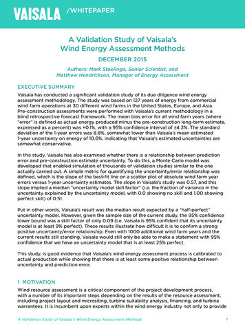
USER'S GUIDEThe device is equipped with the following label:The Ceilometer CL51 is intended for operation in an area restricted frompublic access, and to be pointed vertically or near-vertically.Invisible laser radiation is emitted through the aperture on top of theceilometer. The location of the laser aperture is shown in Figure 1 below.0912-216Figure 1Location of Laser Aperture on Ceilometer CL5114 M210801EN-A
Chapter 1 General InformationThe following precautions must be followed during the service andmaintenance of the instrument:WARNINGNever look directly into the Ceilometer Transmitter or CeilometerOptics with magnifying optics (such as glasses, binoculars, andtelescopes). Never remove the Ceilometer Transmitter from its normalposition without first switching off both the line and the battery powerand detaching the transmitter ribbon cable from the Ceilometer EngineBoard.When operating, avoid looking at the ceilometer unit from the beamdirection. When tilting the unit, make sure that it is not being viewedfrom the beam direction with magnifying optics.Only trained personnel should perform maintenance functions. Accessto the work area by unauthorized persons during service operationsmust be prevented.ESD ProtectionCAUTIONThe equipment contains parts and assemblies sensitive to damage byElectrostatic Discharge (ESD). Use ESD precautionary procedures whentouching, removing or inserting any objects inside the equipmenthousing.Electrostatic Discharge (ESD) can cause immediate or latent damage toelectronic circuits. Vaisala products are adequately protected againstESD for their intended use. However, it is possible to damage the productby delivering electrostatic discharges when touching, removing, orinserting any objects inside the equipment housing.To make sure you are not delivering high static voltages yourself:- Handle ESD sensitive components on a properly grounded andprotected ESD workbench. When this is not possible, ground yourselfto the equipment chassis before touching the boards. Ground yourselfwith a wrist strap and a resistive connection cord. When neither of theabove is possible, touch a conductive part of the equipment chassiswith your other hand before touching the boards.- Always hold the boards by the edges and avoid touching thecomponent contacts.VAISALA 15
USER'S GUIDERecyclingRecycle all applicable material.Dispose of batteries and the unit according to statutory regulations. Donot dispose of with regular household refuse.Regulatory CompliancesVaisala Ceilometer CL51 complies with the Low Voltage Directive(2006/95/EC) and the EMC-Directive (2004/108/EC). The theconformity is shown by compliance with the following standards:- EN 60950-1:2006 Information technology equipment - Safety - Part 1:General requirements- EN 61326-1:2006-04 Electrical equipment for measurement, controland laboratory use - EMC requirements - Basic immunity testrequirements.- EN 55022:2006 Am 1:2007 to EN55022:2006 Class B. Informationtechnology equipment - Radio disturbance characteristics - Limits andmethods of measurement.- EN 61000-3-2 (2006) Limits for harmonic current emissions- EN 61000-3-3 (2008) Limitation of voltage changes, voltagefluctuations and flicker in public low-voltage supply systems.License AgreementAll rights to any software are held by Vaisala or third parties. Thecustomer is allowed to use the software only to the extent that is providedby the applicable supply contract or Software License Agreement.16 M210801EN-A
Chapter 1 General InformationWarrantyFor certain products Vaisala normally gives a limited one-year warranty.Visit our Internet pages for more information and our standard warrantyterms and conditions: www.vaisala.com/services/warranty.html.Please observe that any such warranty may not be valid in case ofdamage due to normal wear and tear, exceptional operating conditions,negligent handling or installation, or unauthorized modifications. Pleasesee the applicable supply contract or Conditions of Sale for details of thewarranty for each product.VAISALA 17
USER'S GUIDEThis page intentionally left blank.18 M210801EN-A
Chapter 2 Product OverviewCHAPTER 2PRODUCT OVERVIEWThis chapter introduces the features, advantages, and the productnomenclature.Introduction to Vaisala Ceilometer CL51The Vaisala Ceilometer CL51 measures cloud height and verticalvisibility.The Ceilometer CL51 employs pulsed diode laser LIDAR technology(LIDAR Light Detection and Ranging), where short, powerful laserpulses are sent out in a vertical or near-vertical direction. The reflectionof light, backscatter – caused by haze, fog, mist, virga, precipitation, andclouds – is measured as the laser pulses traverse the sky. The resultingbackscatter profile, that is, the signal strength versus the height, is storedand processed, and the cloud bases are detected. The time delay betweenthe launch of the laser pulse and the detection of the backscatter signalindicates the cloud base height.The Ceilometer CL51 is able to detect three cloud layers simultaneously.If the cloud base is obscured due to precipitation or ground-based fog, theCL51 reports Vertical Visibility. There is no need for adjustments in thefield. The embedded software includes several service and maintenancefunctions and gives continuous status information from internalmonitoring. The software is designed to give the full backscatter profile.The CL51 includes data messages used in the CL31 and LD40. Thereforeit is easy to transfer from older ceilometer versions to the CL51.The Ceilometer CL51 is shown in Figure 2 on page 20.VAISALA 19
USER'S GUIDE0912-229Figure 2Vaisala Ceilometer CL51The following numbers refer to Figure 2 above:12 Shield Measurement Unit20 M210801EN-A
Chapter 2 Product OverviewProduct NomenclatureMain parts of the Ceilometer CL51 are listed in Table 4 and optionalparts in Table 5 below.Table 4Vaisala Ceilometer CL51 Main 14592CLH311-115CLH311
VAISALA_ 13 The Laser Transmitter CLT521, Receiver CLR321, and AC Power Unit CLP311 are equipped with the following warning label: WARNING! HIGH VOLTAGE INSIDE THIS ENCLOSURE The Internal Heater CLH311 can be hot and is equipped with the .


![Humidity101 HumidityTheory.pptx [Read-Only] - Vaisala](/img/46/humidity101-humiditytheorytermsdefinitions.jpg)