Transcription
AN INTRODUCTION TOMIGWELDINGwws group support@weldability.comWARNING:This document contains general information about the topic discussed herein. This document is not anapplication manual and does not contain a complete statement of all factors pertaining to that topic.The installation, operation and maintenance of arc welding equipment and the employment ofprocedures described in this document should be conducted only by qualified persons in accordancewith applicable codes, safe practices, and manufacturers’ instructions.Always be certain that work areas are clean and safe and that proper ventilation is used. Misuse ofequipment, and failure to observe applicable codes and safe practices can result in serious personalinjury and property damage.www.weldability.com
an introduction to MIG weldingGeneralMIG (Metal Inert Gas) welding, also known as MAG (Metal Active Gas) and in the USA as GMAW (Gas Metal ArcWelding), is a welding process that is now widely used for welding a variety of materials, ferrous and non ferrous.The essential feature of the process is the small diameter electrode wire, which is fed continuously into the arc froma coil. As a result this process can produce quick and neat welds over a wide range of joints.Equipment DC output power sourceWire feed unitTorchWork return welding leadShielding gas supply, (normally from cylinder)Power SourceMIG welding is carried out on DC electrode (welding wire) positive polarity(DCEP). However DCEN is used (for higher burn off rate) with certain selfshielding and gas shield cored wires.DC output power sources are of a transformer-rectifier design, with a flatcharacteristic (constant voltage power source). The most common type ofpower source used for this process is the switched primary transformerrectifier with constant voltage characteristics from both 3-phase 415V and 1phase 240V input supplies.The output of direct current after full wave rectification from a 3-phasemachine is very smooth. To obtain smooth output after full wave rectificationwith a 1- phase machine, a large capacitor bank across the output is required.Because of the expense of this, many low cost 1-phase machines omit thiscomponent and therefore provide a poorer weld characteristic.The switches to the main transformer primary winding provide the outputvoltage steps at the power source output terminals.Another method of producing different voltages at the power source outputterminals is to use a Thyristor or a Transistor rectifier instead of a simplediode rectifier. This system offers continuously variable output voltage, which can be particularly useful on robotinstallations and the cost of this type of rectifier can be partly offset with noneed for primary voltage switch or switches and a single tapped maintransformer primary winding.Most MIG powersources have acontactor or relayused to switch theoutputON/OFFwith operations ofthe trigger on theMIG torch. Theswitchoffoperation of thiscontactorisnormally delayedtoallowthewelding wire toBurn back out ofthe molten weld pool. A thermostat is fitted on the hottest point in the powersource, in series with the contactor coil to provide thermal protection to themachine. Power source performance is measured by it’s ability to provide acertain current for a percentage of a 10 minute period before “Thermal CutOut”. This is the “Duty Cycle”.page 2 of 16www.weldability.com support@weldability.com
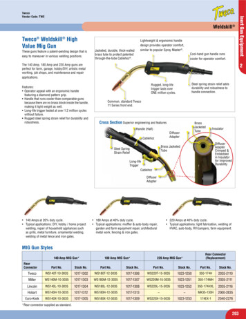
an introduction to MIG weldingThe Wire-feed UnitThe wire-feed unit, or sub-assembly where this is mounted in the power source cabinet (known as a compositeMIG), provides the controlled supply of welding wire to the point to be welded. According to the welding wire size andArc voltage provided by the power source, a constant rate of wire speed is required, in MIG welding the powersource provides Arc voltage control and the wire feed unit provides welding wire speed control, ( in MIG this equatesto welding current ).Most modern wire feed units control the wirefeed speed via a DC motor and thyristorcontrol PCB to provide continuos control ofArmature volts and hence RPM of motor.The wire feed motor spindle has a feedroller fitted and another pressure roll,adjustable spring mounted to lightly grip thewire and push it up the length of the MIGtorch.Various combinations of drive system areused by different manufacturers, theseinclude:driven feedrolldriven feedrolltwo driven feedrollstwo driven feedrollsandandandandpressure driven pressure rolldriven pressure rollpressure driven pressure rolltwo driven pressure rollsalsorifled V-shaped feedrolls size dependant groovesV-shaped feedrollssize dependant groovesU-shaped feedrollssize dependant groovesflat, plain pressure rollsflat, knurled pressure rollsV-shaped pressure rollssize dependant groovesU-shaped pressure rollssize dependant groovesThe following groups of illustrations show the types ofproblems encountered when wire-feed roll parameters(pressure and type) are applied incorrectly.It is apparent from these images that correct selection of wire feedrollgroove shape and feedroll pressure is essential in obtaining optimum wire feed conditions.page 3 of 16www.weldability.com support@weldability.com
an introduction to MIG weldingChoosing The Wire FeederThese types of wire feeders can be used with MIGtorches up to a maximum of 4m (the shorter the better)for hard welding wires and, with great care and a highlevel of maintenance, up to a maximum of 3m with softwires like aluminium.To overcome this limitation the wire feed unit can bemade as a separate portable unit so the welder can workat a great distance from the power source.Push-Pull Wire-Feed SystemsFor soft welding wires, special systems are used wherethe torches have an internal drive mechanism to pull thewelding wire in addition to the push drive system in thewire feed unit.Spool-On-Gun Wire-Feed SystemsOthers have a small spool of wire which is mounted onthe torch and a drive system in the handle feeds the wiredirectly to the point of weld.The MIG TorchThis provides the method of delivery from the wirefeed unit to the point at which welding is required.The MIG torch can be air cooled or water cooled andmost modern air cooled torches have a single cablein which the welding wire slides through a Liner. Gasflows around the outside of this Liner and around thetube the Liner sits in is the power braid and triggerwires. The outer insulation provides a flexible cover.Water cooled MIG torches are similar to the above,but gas hose, liner tube, power lead (including waterreturn pipe), water flow pipe and trigger wires are allseparate in an outer sleeve.Most industrial MIG equipment uses a standardEuropean MIG torch connector for easy connectionof torch, some low cost smaller units use individualmanufacturers fittings.The important areas of maintenance are: Liners arein good condition and correct type and size; Contacttips are lightly fitted, of correct size and goodcondition.page 4 of 16www.weldability.com support@weldability.com
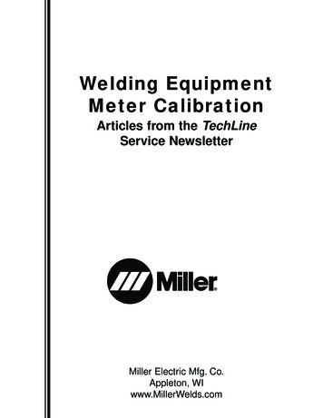
an introduction to MIG weldingShielding GasThis is a complicated area with many various mixtures available, but the primary purpose of the shielding gas in theMIG process is to protect the molten weld metal and heat affected zone from oxidation and other contamination bythe atmosphere.The shielding gas should also have a pronounced effect on the following aspects of the welding operation and theresultant weld. Arc CharacteristicsMode of Metal TransferPenetration and Weld Head ProfileSpeed of WeldingUndercutting TendencyCleaning ActionWeld Metal Mechanical PropertiesA basic position or starting point would beAluminiumMagnesiumCopper AlloysSteel-ArgonHeliumArgon - Helium MixCO2 not commonly used *today, Ar-CO2 mix ispreferredMetal Transfer Across The ArcThe operating characteristics of MIG welding is described by the four basic modes of weld metal transfer from theelectrode to the work:* Short circuiting transfer* Globular transfer* Spray transfer* Pulsed spray transferThe mode of weld metal transfer is determined bythe following:* Welding current* Electrode size* Electrode composition* Electrode stick out* Shielding gasShort Circuiting TransferShort Circuit Weld Metal TransferShort circuiting transfer uses the lowest welding currents and voltages, which consequently produces very low heatinput. In this mode of welding, the metal is not transferred across the arc gap, but from the electrode to the work onlyduring a short period when the welding wire is in contact with the weld pool. When the electrode wire tip touches theweld pool, the arc extinguishes, the voltage goes down and amperage rises. At this moment, metal is transferredfrom the melted electrode tip to the weld pool with the help of surface tension of the melted weld metal. When thedroplet from the tip of thewire passes to the weld poolthere is no more metalconnection and the arc is reestablished. At the heat ofthe arc tip, the electrode ismelted and as the wire is fedtowards the weld pool thenext short circuit occurs. Therate of current increaseduring the short circuit iscontrolled by the induction ofthe power source, whereasthe re-ignition and theSelection of gases for MIG with short-circuiting metal transfermaintenance of the arc are provided by theenergy stored in the inductor during the short circuiting period.page 5 of 16www.weldability.com support@weldability.com
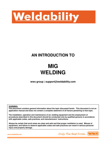
an introduction to MIG weldingThe electrode contacts the weld pool at a random frequency, which ranges from 20 to 200 contacts per seconddepending on the current voltage and amperage. The drop size and the short circuit duration are influenced by thecomposition of the shielding gas, which affects the surface tension of the molten metal. This mode of metal transferin MIG is normally applied with CO2-rich mixed shielding gas on ferrous metals.A correctly set arc produces a small amount of spatter and arelatively small, fast freezing and easily controlled weld pool.Because of this, this model of metal transfer is well suited for thinsections, for off-position welding and for building up bridges onlarge root openings.Globular Metal TransferGlobular metal transfer occurs at relatively low operating currentsWeld Metal Transfer Characteristicsand voltages but these are still higher than those used in shortcircuiting transfer. This metal transfer mode is characterised by adrop, two or three times larger in diameter than the wire, formedat the tip of the electrode. This droplet is detached from the tip of the electrode by the effect of a pinch force and thetransfer of the droplets in irregular form across the arc is aided by the effect of the weak electromagnetic and stronggravity forces. As the droplets grow on the tip of the wire electrode they wobble around and disturb the arc plasmastability. Consequently, the heat-affected zone in the work becomes narrow, penetration of the weld becomes small,and the weld deposit is irregular and large amounts of spatter takes place.When the arc length is too short (low voltage) the droplets can touch the weld-pool and short out the circuit beforedetaching from the wire. This causes a considerable amount of spatter. Therefore the arc must be long enough to letthe droplets detach freely from the electrode tip without touching the weld pool.The globular metal transfer mode can be obtained with all types of shielding gas. With CO2 shielding gas, globularmetal transfer occurs at most of the operating current, amperage and voltage levels. Large molten metal droplets aretransferred across the welding arc mainly by the action of gravity. Therefore this mode of working in MIG is appliedto the welding of mild steel in flat and horizontal position.Spray TransferUnder an argon-rich shielding gas, increasing the current and voltage causes a new mode of metal transfer toappear: the tip of the wire electrode is tapped,the sizes of the droplets become smaller andthey are directed axially in a straight line fromthe wire to the weld pool. The current levelabove by which this mode of metal transferbegins is called transition current. Thedroplets are much smaller than the diameterof the wire and they detach with pinch forcemuch more rapidly than with the globulartransfer mode, there is very little spatter andthe surface of the weld bead is smooth.Pulsed Spray TransferThe rate of transfer of droplets can vary fromless than one hundred times of a second upto several hundred times of a second. As thecurrent increases the droplet size decreasesand the frequency increases. If the currentlevel in this made of transfer is high enough the necking effect of the pinch force and the arc forces accelerate thedroplets to velocities which overcome the gravity forces. Therefore spray transfer can be used under certainconditions in out-of-position welding. Although the high deposition rate produces a large weld-pool, this can not besupported only by the surface tension of the molten metal in vertical and overhead welding. This problem isovercome by a new technique called pulsed current transfer.Pulsed Current Transferpage 6 of 16www.weldability.com support@weldability.com
an introduction to MIG weldingThe Pulsed mode of metal transfer in MIG is used for applications where a good penetration and reduced heatinput are required. A pulsed current transfer is a spray type of transfer that occurs at regularly spaced intervalsinstead of constantly. This mode of metal transfer can only be produced if the power source is able to supply apulsed current. The level of a welding current supplied by a pulsing type of power source varies between highand low levels.Whereas high level is above the transition current and produces the droplets, low level or background currenthas only sufficient energy to sustain the arc. In this system of transfer, the droplets have a size equal to thediameter of the wire electrode and theoretically the machine can be set up so that one drop of molten metal canbe transferred across the arc
welding wire in addition to the push drive system in the wire feed unit. Spool-On-Gun Wire-Feed Systems Others have a small spool of wire which is mounted on the torch and a drive system in the handle feeds the wire directly to the point of weld. This provides the method of delivery from the wire feed unit to the point at which welding is required. The MIG torch can be air cooled or water .