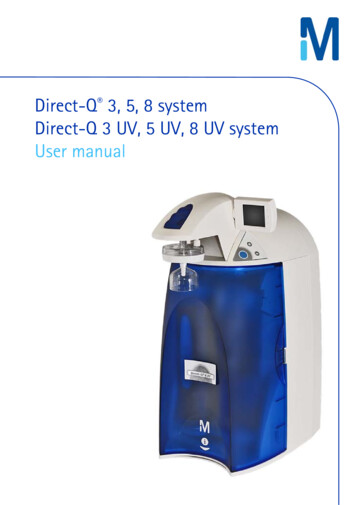
Transcription
On the performance of direct piezoelectric rotationalaccelerometers in experimental structural dynamicsArmin Drozga , Jakob Rogelja , Gregor Čepona, , Miha BoltežaraaFaculty of mechanical engineering, University of LjubljanaAbstractRotational responses are comparing to the translational responses less frequently used in the experimental structural dynamics. Even though they represent half of all the existing degrees of freedom they are often omitted, sincethey are difficult to measure. Nevertheless, they have an important contribution in structural dynamic modifications, model validation, substructuringetc. Therefore in this paper a performance evaluation of two direct piezoelectric rotational accelerometers is made in order to show the possibilities oftheir usage in the structural dynamic applications. Additionally, the resultsare compared to a commonly used method of approximated rotational responses obtained from two offset translational accelerometers. Sensors weretested with impact and sine-sweep excitations. Data is analyzed in the formof frequency response functions and compared to a numerical reference witha coherence criterion. The quality of directly obtained rotations are expectedto have great potential in structural dynamics.Keywords: Rotational degrees of freedom, direct piezoelectric rotationalaccelerometer, indirect rotational reconstruction, frequency responsefunction, coherence criterion1. IntroductionSystem’s moment inertia is defined by rotational degrees of freedom (DoFs).The latter represents half of all the existing DoFs and can be expressed inthe form of time series, frequency response functions (FRFs) or modal shape Corresponding authorEmail address: gregor.cepon@fs.uni-lj.si (Gregor Čepon)Preprint submitted to MeasurementsMay 17, 2018
slopes. Their implementation in a numerical model is a common procedure,however several issues appear whenever they are obtained experimentallydue to the data contamination [1–3]. Consequently, this represents somelimitations in the applications such as structural dynamic modifications [4],model updating and validation [5], acoustics [6] as well as dynamic substructuring [7, 8]. Nevertheless, since the quality experimental rotational DoFsinfluence the accuracy of structural dynamic characteristics, the methods toefficiently measure the rotations are still the subject of ongoing research.A lot of effort has been invested so far in sensors development to obtainrotational motion as well as procedures to apply a pure moment excitation. Ageneral overview of some original methods including T-block element, massadditive techniques, finite differences, estimation techniques, simple transducers and usage of laser setup are summarized in papers [9, 10]. Thosemethods set standards upon which newer procedures were proposed in recentyears in order to improve their deficiencies. Procedure of finite differencestheory, together with two offset translational accelerometers can be foundin [11, 12]. Methods to apply pure moment excitation for mass normalizedFRFs has been proposed in [5, 13, 14]. A new type of sensors based on bimorph materials [15, 16], micro electro mechanical systems (MEMS) [17, 18],strain gages [19] and piezoelectric materials [20] has been also developed inrecent years. However, extensive research in this field still does not providereliable procedure that would gain much popularity in the real applications.Therefore, researcher have also tried to combine experimental and numericalresults [21] or even completely replace the rotational responses based on thetranslational approximations [7].Omitting or replacing rotational responses with approximation may besufficient whenever analytical or numerical data are used. However, any approximation normally relays on predetermined assumptions, which may bevery difficult to be satisfied in the practice. Further, taking into accounttypical data contamination [22–24], consequently leads to the erroneous finalresult. Thus, in this paper, performance evaluation of force-excited rotationalresponses is made with two commercially available direct quartz based piezoelectric rotational accelerometers and indirect reconstruction of rotationalresponses based on T-element with two offset translational responses. Incontrast to classical translational accelerometers, direct rotational accelerometers are rarely used in the field of experimental structural dynamic. Thisis related with their high cost, additional experimental work and expansionof DoFs in the numerical model. Moreover, difficulties with pure moment2
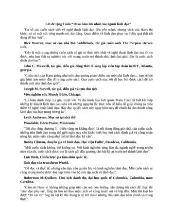
excitations prevents to obtain mass normalized modal shape slopes. Therefore, direct rotational sensors are more frequently used for active control ofoscillating shafts and car crash testings [25]. The latter are more typicalfor active control of oscillating shafts and car crash testings [25]. However,lightweight and robust construction as well as wide dynamic and frequencyrange seems to be suitable also for structural dynamics applications. Therefore, a comprehensive analysis is performed in order to assess the adequacyof direct rotational sensors for experimental structural dynamics analyses. Acomparison of FRFs associated with rotational DoFs is performed on a steelplate with several combinations between excitation and measuring points.The most frequently used reconstructed rotational responses obtained usingT-element are compared with an old and new generation of Kistler Type8840 direct rotational accelerometers. The analysis is captured by proposingimpact and sine sweep excitations applied with modal hammer and electrodynamics shaker. The quality of the measured FRFs is assessed based on acomparison with numerical reference using visual inspection and coherencecriterion.The following section briefly presents a quartz based piezo-electric rotational accelerometer and T-element for indirect approximation of rotationalDoFs, in third section an experimental setup is explained, followed by testingresults and coherence criterion.2. Rotational sensorsA brief presentation and technical specifications of direct piezoelectricrotational accelerometers and indirect T-element are given in this section asthey are used in a performance evaluation test.2.1. Direct rotational accelerometerPiezoelectric rotational accelerometers are direct sensors for obtaining angular motion of a structure. They are based on a very stable quartz crystaland do not use standard voltage mode piezoelectric sensor couplers (IEPEtypes), but are powered by any commercially available 20-30 VDC powersupply. In this paper an older generation Kistler Type 8840 and a newergeneration Kistler Type 8840B are analyzed. Both of them have two spatially separated quartz shear-mode-element assemblies [25]. Direct sensing ofrotational DoFs has several benefits comparing to the indirect options. One3
of the most important quality is a sensitivity-matching of each quartz element, where an error of 0.25 % in sensitivity-matching can contribute 12.3 %error to the final result [25]. Further, local flexibility is not an issue due tothe small size and one point attachment. Moreover, lightweight, compactand robust construction as well as wide dynamic and frequency range meetall the typical experimental modal analysis (EMA) conditions. Technicalspecifications are presented in Table 1. For additional information a readeris referred to [25].Table 1: Technical specifications of quartz-based piezoelectric rotational accelerometer,Kistler Type 8840 and 8840B.Technical dataAcceleration rangeSensitivityFreq. responseResonant frequencyTransverse sensitivityMassUnitsk rad/s2µV/rad/s2HzkHz%g(a)Type 8840 15035.51. . . 200023 1.518.5Type 8840B 86000.5. . . 300023 223(b)Figure 1: Direct rotational accelerometers: a) Kistler Type 8840, b) Kistler Type 8840B.2.2. Indirect measurement of rotations using T-elementT-element was used for indirect reconstruction of rotational motion asproposed by Ewins et al. [26]. This method presents one of the most commonly used procedure to experimentally obtain rotations. It consist of two4
precisely positioned translational accelerometers attached on a steel T shapeelement with adhesive mounting base (Figure 2a). Reconstruction of rotational DoFs is schematically presented in Figure 2b. The parameters ofT-element are shown in Figure 3 and given in Table 2.x 1x 2 - x 1 2ax 2 a(a)(b)Figure 2: T-element: a) Assembly of T-element, b) Reconstruction of rotational DoFs.Figure 3: Technical documentation of T-element [mm].5
Table 2: Technical specifications of translational accelerometers and T-element.Technical dataBrüel & KjærType 4507-B-004700100.3.600019 54.6UnitsAcceleration rangems 2SensitivitymV/ms 2Freq. responseHzResonant frequencykHzTransverse sensitivity%Massg1T-element(with sensors)/// 4.2 (FEM1)/12Finite Element Method3. Experimental setupExperimental setup is schematically presented in Figure 4. Impact excitation was performed with a modal hammer and a sine sweep excitation withan electrodynamic shaker powered by power amplifier. Excitation signalswere transfered through NI DAQ output module. On the other side signalswere acquired with NI DAQ input module and analyzed with Python script.Two direct piezoelectric rotational sensors as well as indirect T-element weremounted with a M5 screw and tightened with a 2 Nm of torque on a freefree supported steel plate. Dimensions of plate as well as experimental pointlocations and directions are shown in Figure 5a.6
EuropowerEP 4000High pass 5 HzNI 9263PCB 086C03LDS V406NI 9233NI CDAQ 9184B&K 4507B 004Steel plateKistler 8840& 8840BFigure 4: Experimental setup.252423221815171614131211y8654321109730 mm330 mm2120193m zm00xtested pointsm 23 kg(a)(b)Figure 5: Experimental setup: a) Dimensions and measuring points on a steel plate, b)T-element measurement setup.7
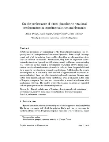
4. Testing and resultsExperimental investigation was performed in order to evaluate performance capabilities of direct and indirect piezoelectric rotational accelerometers in the experimental structural dynamics. Sensors were tested usingtwo excitation types. The first one is impact excitation applied by a modalhammer and the second one a sine sweep excitation performed with an electrodynamic shaker. Measurements were obtained in all mutual combinationsbetween four input and output experimental points (Figure 5a). All together 16 FRFs for each sensor. The results were compared with FRFs froman equivalent numerical model up to 3 kHz. Numerical model is made of 2Dmesh with around 1800 four node shell elements and six DoFs in each node(around 11 k DoFs altogether). Elastic modulus was 210 GPa, Poisson’s ratio 0.3 and density of 7849 kg/m3 . Preliminary analysis of 23 kg steel plateshows that the mass of additionally mounted sensors has a neglegible effecton the dynamic properties of the system. Therefore sensor’s mass was notincluded in the numerical model. The first pair of FRF indexes marks outputor response and the second pair input or excitation position and direction.Beside graphical presentation, an additional correlation with a numerical reference is made using coherence criterion. This is unity scaling criterion thatcompares two different FRFs for the same input-output position and direction. Values closer to one represent perfect correlation and on the other sidevalues closer to zero no correlation at all. Coherence criterion is expressedas [27]:cohij num (Hnum Hexp Hexp ijij )(Hijij );exp expnum num2 (Hij Hij Hij Hij )i 1, 2, 3, 4;j 1, 2, 3, 4, (1)where Hnumand Hexpijij stand for numerical and experimental FRF for particular output i and input j location and Hnum*as well as Hexp*for their complexijijconjugation.4.1. Impact excitationImpact excitation was performed using a modal hammer and aluminumtip within frequency band of excitation up to 4.2 kHz. Two transfer pointFRFs for all three sensors are compared with a numerical FRFs (Figure 6).Indirectly obtained rotational responses using T-element poorly defineanti-resonance regions. Those are local characteristics of a tested system8
10 410 3rad ]A [Ns210 210 110 010 -1NumericalT-elementKistler 8840Kistler 8840B10 -210 -3050010001500f [Hz]200025003000(a)10 310 2rad ]A [Ns210 110 010 -1NumericalT-elementKistler 8840Kistler 8840B10 -210 -3050010001500f [Hz]200025003000(b)Figure 6: FRFs induced by impact excitation: a) FRF7rz7x , b) FRF16rz22x .mostly influenced by sensor’s position and cross sensitivity effect. The latter is related by geometrical imperfections of T-element and mismatch oftranslational accelerometer’s sensitivity factor. Moreover the position is alsoaffected due to the big size and misalignment caused by test operator. Never9
0.75160.570.2555 7 16 22Input [Node num.](a)01220.75160.570.2555 7 16 22Input [Node num.](b)0Output [Node num.]122Output [Node num.]Output [Node num.]theless, natural frequencies are well aligned with a numerical FRFs but theiramplitudes and corresponding damping factor are quite inaccurate. Noiselevel is fairly low through entire frequency range but overall quality of thesignal is not suitable for further use in applications such as dynamic substructuring, where even small misalignment of anti-resonances leads to erroneousfinal results [22–24]. Coherence values in Figure 7a are in average equal to0.7. On the other side a directly obtained rotational responses seem to provide more accurate results in terms of natural frequencies, their amplitudesand also anti-resonance regions within entire 3 kHz frequency range. Despitecalibration limit at 2 kHz for Type 8840 accelerometer the results match witha numerical reference within entire frequency range. Noise level for that particular sensor is higher comparing to the newer Type 8840B accelerometerespecially at lower frequencies below 500 Hz. Amplitudes and damping factors are in both cases quite well aligned with a numerical FRFs. Coherencevalues in Figures 7b and 7c are around 0.9 with slightly higher values for anewer Type 8840B. In the case of same node and different DoFs measurement a spurious peak appears around 1.6 kHz for of all three sensors. Reasonfor this is probably related with misalignment of sensors position deviatingfrom exact location. However, small and robust construction of direct rotational sensors as well as optimal position of well matched quartz-latticesensures satisfied results that are comparing to indirect option more suitablefor structural dynamic application. Beside lower level of noise of the newerType 8840 the obtained results are practically the same for both sensors.1220.75160.570.2555 7 16 22Input [Node num.]0(c)Figure 7: Coherence values between numerical and experimental FRFs: a) T-element (coh.avg. 0.69), b) Kistler Type 8840 (coh. avg. 0.88), c) Kistler Type 8840B (coh. avg. 0.91).10
4.2. Sine sweep excitationSine sweep excitation was applied using electrodynamic shaker in a frequency band between 10 Hz and 3 kHz. Two typical transfer point FRFs arepresented in Figure 8. Probably due to the more controlled input of energyat each frequency, low level of noise is present for all three sensors. Similarto impact excitation, a T-element provide less accurate results comparing todirect sensors especially above 1.5 kHz. Although the natural frequenciesare well correlated with the numerical reference, overall shape of the FRFis completely erroneous. Due to this, the values of coherence criterion inFigure 9a are in average 0.6. With both direct sensors better definition ofstatic response and lower frequency responses are achieved. However, multiple spurious peaks appears around natural frequencies. Analogous to thehammer impact, mode around 1.6 kHz appears probably due to offset of sensor position. The latter, slightly decrease a coherence values on the diagonalin Figures 9b and 9c but an average still remains around 0.87. In general aresponses below 2 kHz are more correlated with a numerical FRFs comparing with a higher frequency responses. This is true for both resonance andanti-resonance regions for all three sensors.11
10 410 3rad ]A [Ns210 210 110 010 -1NumericalT-elementKistler 8840Kistler 8840B10 -210 -3050010001500f [Hz]200025003000(a)10 310 2rad ]A [Ns210 110 010 -1NumericalT-elementKistler 8840Kistler 8840B10 -210 -3050010001500f [Hz]200025003000(b)Figure 8: FRFs induced by sine sweep excitation: a) FRF7rz7x , b) FRF16rz22x .12
0.570.2555 7 16 22Input [Node num.](a)01220.75160.570.2555 7 16 22Input [Node num.](b)0Output [Node num.]0.7516Output [Node num.]Output [Node num.]1221220.75160.570.2555 7 16 22Input [Node num.]0(c)Figure 9: Coherence values between numerical and experimental FRFs: a) T-element (coh.avg. 0.61), b) Kistler Type 8840 (coh. avg. 0.86), c) Kistler Type 8840B (coh. avg. 0.89).13
5. ConclusionsThe objective of this paper was to access the performance capabilities ofcommercially available direct rotational accelerometers for identification ofrotational DoFs in the field of structural dynamics. Comparison consisted oftwo direct rotational sensors and commonly used indirect rotational sensorbased on a reconstructed translational responses. Test was performed on asimple steel plate for different input and output locations. Plate was excitedwith impact and sine-sweep excitations and responses obtained in the formof FRFs. The results from both direct rotational accelerometers are in general more accurate comparing to the reconstructed rotational responses fromT-element. This is true for global systems characteristics such as natural frequencies, the height of their amplitudes and damping factors as well as localcharacteristics; positions of anti-resonances. The latter are very sensitive tosensors position which is in the case of T-element difficult to control due to itssize and inevitable minor dislocations of two accelerometers. Cross sensitivity is the next influential feature more effectively canceled out within directsensors based on completely controlled construction environment, which isdifficult to achieve by construction of the T-element. T-element produceslower level of noise for both excitation types in entire frequency range. Rotational responses obtained using direct accelerometers are relatively goodaligned with numerical reference within 3 kHz frequency range, which is notthe case for indirect rotational responses, where the increasing deviation isobserved above 2 kHz.Overall, compact and robust construction of direct rotational sensors,simplicity of use and nevertheless the quality of the FRF responses seemsto have great potential in the variety of structural dynamic applications.Comparing to indirect options, they are far more accurate and reliable despitethe slightly higher levels of noise in signals. However, there is a drawback witha direct rotational sensors, since their price is noticeable higher comparingto classical translational accelerometers. Cost of individual sensor is in therange of a few thousand dollars.References[1] K. Tomczyk, E. Layer, Accelerometer errors in the measurement of dynamic signals, Measurement 60 (2015) 292–298.14
[2] G. D’Emilia, A. Gaspari, E. Natale, Evaluation of aspects affecting measurement of three-axis accelerometers, Measurement 77 (2016) 95–104.[3] K. Tomczyk, Impact of uncertainties in accelerometer modeling on themaximum values of absolute dynamic error, Measurement 80 (2016) 71–78.[4] T. L. Schmitz, G. S. Duncan, Three-Component Receptance CouplingSubstructure Analysis for Tool Point Dynamics Prediction, Journal ofManufacturing Science and Engineering 127 (4) (2005) 781–790.[5] A. S. Elliott, A. T. Moorhouse, G. Pavić, Moment excitation and themeasurement of moment mobilities, Journal of Sound and Vibration331 (11) (2012) 2499–2519.[6] A. T. Moorhouse, A. S. Elliott, T. A. Evans, In situ measurement of theblocked force of structure-borne sound sources, Journal of Sound andVibration 325 (4) (2009) 679–685.[7] D. de Klerk, D. J. Rixen, S. N. Voormeeren, F. Pasteuning, Solving theRDoF Problem in Experimental Dynamic Substructuring, in: Proceedings of the XXVI International Modal Analysis Conference, Orlando,FL, Society for Experimental Mechanics, Bethel, CT, 2008.[8] A. Drozg, G. Čepon, M. Boltežar, Full-degrees-of-freedom frequencybased substructuring, Mechanical Systems and Signal Processing 98(2018) 570–579.[9] M. L. M. Duarte, D. J. Ewins, Rotational degrees of freedom for structural coupling analysis via finite-difference technique with residual compensation, Mechanical Systems and Signal Processing 14 (2) (2000) 205–227.[10] A. S. Morris, R. Langari, Chapter 20 - Rotational Motion Transducers, in: Measurement and Instrumentation (Second Edition), AcademicPress, Boston, 2016, pp. 599–632.[11] S. S. Sattinger, A Method for Experimentally Determining RotationalMobilities, The Journal of the Acoustical Society of America 64 (6)(1978) 1734–1734.15
[12] T. J. Gibbons, E. Öztürk, N. D. Sims, Rotational degree-of-freedomsynthesis: An optimised finite difference method for non-exact data,Journal of Sound and Vibration 412 (2018) 207–221.[13] P. Varoto, M. Lofrano, T. Cicogna, L. Oliveira, Moment Mobility FRFMeasurement Techniques, in: Proceedings of the XXIV InternationalModal Analysis Conference, St. Louis, MO, Society for ExperimentalMechanics, Bethel, CT, 2006.[14] Y. Champoux, V. Cotoni, B. Paillard, O. Beslin, Moment excitation ofstructures using two synchronized impact hammers, Journal of Soundand Vibration 263 (3) (2003) 515–533.[15] M. Bello, A. Sestieri, W. D’Ambrogio, F. La Gala, Development of arotation transducer based on bimorph PZTS, Mechanical Systems andSignal Processing 17 (5) (2003) 1069–1081.[16] H. Xiaoyan, S.-F. Ling, K. H. Heng, A New Transducer for Rotationaland Translational Impedance Measurement, Journal of Intelligent Material Systems and Structures 19 (10) (2008) 1207–1215.[17] A. Gola, E. Chiesa, E. Lasalandra, F. Pasolini, M. Tronconi, T. Ungaretti, A. Baschirotto, Interface for MEMS-based rotational accelerometer for HDD applications with 2.5 rad/s2 Resolution and digital output,Sensors Journal, IEEE 3 (2003) 383–392.[18] A. Jacquelyn, M. Hakhamaneshi, D. Wilson, B. L. Kutter, Advances inMeasuring Rotation with MEMS Accelerometers, in: 10th InternationalConference on Physical Modeling in Geotechnics, Perth, Australia, 2014.[19] C. Yuan, L. P. Luo, Q. Yuan, J. Wu, R. J. Yan, H. Kim, K.-S. Shin, C.S. Han, Development and evaluation of a compact 6-axis force/momentsensor with a serial structure for the humanoid robot foot, Measurement70 (2015) 110–122.[20] H. Lv, L. Qin, J. Liu, Principle Research on a Single Mass Six-Degreeof-Freedom Accelerometer With Six Groups of Piezoelectric Sensing Elements, IEEE Sensors Journal 15 (6) (2015) 3301–3310.[21] L. Thibault, A. Butland, P. Avitabile, Variability Improvement of KeyInaccurate Node Groups – VIKING, in: Topics in Modal Analysis II,16
Volume 6, Conference Proceedings of the Society for Experimental Mechanics Series, Springer New York, 2012, pp. 603–624.[22] D. de Klerk, D. J. Rixen, S. N. Voormeeren, General framework for dynamic substructuring: History, review, and classification of techniques,AIAA Journal 46 (5) (2008) 1169–1181.[23] D. de Klerk, How Bias Errors Affect Experimental Dynamic Substructuring, in: Proceedings of the 28th International Modal Analysis Conference (IMAC XXVIII) Jacksonville, FL, Springer New York, 2011, pp.1101–1112.[24] D. de Klerk, S. N. Voormeeren, Uncertainty Propagation in Experimental Dynamic Substructuring, in: Proceedings of the Twenty SixthInternational Modal Analysis Conference, Orlando, FL, Society for Experimental Mechanics, Bethel, CT, 2008.[25] M. Dumont, N. Kinsley, Rotational Accelerometers and Their Usagein Investigating Shaker Head Rotations, in: Sensors and Instrumentation, Volume 5, Conference Proceedings of the Society for ExperimentalMechanics Series, Springer, Cham, 2015, pp. 85–92.[26] D. J. Ewins, M. G. Sainsbury, Mobility Measurement for the Vibration Analysis of Connected Structures, The Shock and Vibration Bulletin (42) (1972) 105–113.[27] M. V. van der Seijs, D. van den Bosch, D. J. Rixen, D. de Klerk, Animproved methodology for the virtual point transformation of measuredfrequency response functions in dynamic substructuring, in: 4th ECCOMAS Thematic Conference on Computational Methods in StructuralDynamics and Earthquake Engineering, Kos Island, Greece, 2013.17
were transfered through NI DAQ output module. On the other side signals were acquired with NI DAQ input module and analyzed with Python script. Two direct piezoelectric rotational sensors as well as indirect T-element were mounted with a M5 screw and tightened with a 2 Nm of torque on a free-free supported steel plate.