Transcription
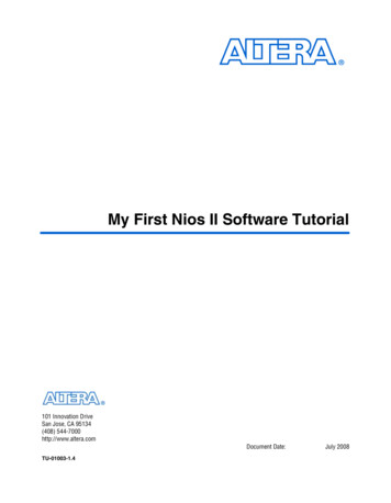
EE102 – Digital Circuit LogicIntroduction to Altera DE2 and Quartus II Design Software1.Objectives 2.Learn basic operation and functionality of DE2 and Quartus software needed toimplement digital circuits.Test a binary counter that has been pre-designed.Altera DE2 BoardThe laboratory assignments will use the Altera DE2 board shown in Figure 1. DE2 can beused to implement sophisticated digital circuits, and the Quartus II software that you will useis a complete design package used even by professional engineers.Note:Since you are new to digital design, do not be surprised if it appears intimidating atfirst. Do not despair; we will selectively introduce the features as needed whileignoring others that we do not need. As the semester progresses, you will understandmore and more features, and by the end of the semester, you will be able to designcomplex circuits using many features of the Quartus II software.You would need some pre developed files named Lab0.zip to complete the project.Download them from the course web page or ask from the TA.1
Figure 1 – Altera DE2 Development and Education BoardNote the set of switches SW0 – SW17, and push buttons KEY0-KEY3 that provide theinputs to circuits you will build, as well as light-emitting diodes LED0-LED17, eight 7segment display units, and a LCD display unit that can be used for observing the outputs.The red switch on the left side is the power switch, and the USB port on top left connects theboard to a computer. Specifications and features of DE2 **2
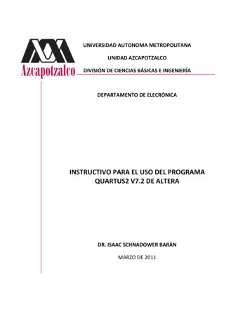
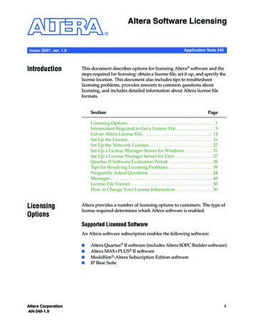
3. A Simple Binary CounterSW1 (Up/Down)SW0 (Enable)KEY0(Pulse)LED-3 LED-2 LED-1 LED-0Figure 2 – Schematic diagram of a binary counterFor this laboratory session we have pre-designed a simple binary counter that you will use. Aschematic diagram of the counter is shown above. It is designed to count and display thenumber of pulses that is applied by pressing KEY0 input. The counter has to be enabled bysetting SW0 high. Setting of SW1 decides whether the counter counts up or down.4. Getting Started with Quartus II SoftwareThis tutorial introduces few basic features of the Quartus II software. It shows how thesoftware can be used to design and implement a circuit specified by means of a schematicdiagram. It makes use of the Graphical User Interface (GUI) to invoke the Quartus IIcommands. Doing this tutorial, the reader will learn about: Creating a project and importing a pre-designed circuitProgramming and configuring the FPGA chip on the Altera‟s DE2 board4.1. Creating a project and importing a pre-designed circuitStep 1: Starting the Quartus II software.Click All Programs ECE Altera Quartus II 9.0 Web Edition Quartus II 9.0 Web Edition from the Windows Start menu to open the Quartus IIsoftware.You should see a display similar to the one in Figure 3. This display consists ofseveral windows that provide access to all the features of Quartus II software, whichthe user selects with the computer mouse. Most of the commands provided byQuartus II software can be accessed by using a set of menus that are located belowthe title bar. For example, in Figure 3 clicking the left mouse button on the menunamed File opens the menu shown in Figure 4. Clicking the left mouse button on theentry Exit exits from Quartus II software. In general, whenever the mouse is used toselect something, the left button is used. Hence we will not normally specify whichbutton to press. In the few cases when it is necessary to use the right mouse button, itwill be specified explicitly.3
Figure 3 – The main Quartus II displayFigure 4 – An example of the File menuFor some commands it is necessary to access two or more menus in sequence. We usethe convention Menu1 Menu2 Item to indicate that to select the desiredcommand the user should first click the left mouse button on Menu1, then within this4
menu click on Menu2, and then within Menu2 click on Item. For example, File Exit uses the mouse to exit from the program. Many commands can be invoked byclicking on an icon displayed in one of the toolbars. To see the command associatedwith an icon, position the mouse over the icon and a tooltip will appear that displaysthe command name.Step 2: Starting a New ProjectEach logic circuit, or subcircuit, being designed with Quartus II software is called aproject. The software works on one project at a time and keeps all information for thatproject in a single directory (folder) in the file system. To begin a new logic circuitdesign, the first step is to create a directory to hold its files. To hold the design filesfor this tutorial, we will use a directory named Lab 0. The running example for thistutorial is a simple circuit that counts in binary.To start working on a new design we first have to define a new design project.Quartus II software makes the designer‟s task easy by providing support in the formof a wizard. Create a new project as follows:(a)Select File New Project Wizard to reach the window in Figure 5, whichindicates the capability of this wizard. Click Next to get the window shown inFigure 6.Figure 5 – Tasks performed by the wizard5
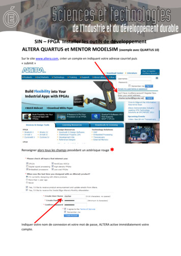
Figure 6 – Creation of a new projectB)Set the working directory to be U:\ECE102\Lab0; of course, you can usesome other directory name of your choice if you prefer. The project must havea name, which is usually the same as the top-level design entity that willbe included in the project. Choose binary counter as the name for both theproject and the top-level entity, in creation window shown in Figure 6.Then click the Next button.Since we have not yet created the directory Quartus II software displays thepop-up message asking if it should create the desired directory. Click Yes,which leads to the window in Figure 7.Note:If you do not have an engineering account you may need to save your data on theDesktop.Step 3: Importing a designThe wizard makes it easy to specify which existing files (if any) should be included inthe project. These files will be added to your project folder but will not be copied intothat.Click the button labeled “ ” in the File Name: field to open the Select File dialogbox. The files that you need are in the Lab0 folder that you download from the web.6
Figure 7 – The wizard for including user-specified design files.Figure 8 – Choose the device family and a specific device7
Then from the Select File dialog box select the binary counter.bdf file and thenclick the Open button. Then the path to the file will be displayed on the File name:text box. Click the Add and file will appear under the File name list.Similarly add the binary counter.sof file.Click Next, which leads to the window in Figure 8.Step 4: Since Quartus II software is used with different types of boards and devices, we haveto specify the type of device in which the designed circuit will be implemented.Choose Cyclone II as the target device family. We can let Quartus II software selecta specific device in the family, or we can choose the device explicitly. We will takethe latter approach. From the list of Available devices:, choose the device calledEP2C35F672C6 which is the FPGA used on Altera‟s DE2 board.Click Next, which opens a window to select other tools that a designer may use.Click Next again, since we do not use such tools in this class.Step 5: A summary of the chosen settings appears in the screen similar to that shown inFigure 9 but with binary counter specified as the new project.Click Finish button, which returns to Quartus II window of Figure 3, withbinary counter specified as the new project in the display title bar.Figure 9 – Summary of project settings4.2. Programming and Configuring the DeviceThe FPGA device must be programmed and configured to implement the designed circuit.For this lab, we will be using a mode called „JTAG Programming‟ to program the device.Step 1: Flip the RUN/PROG switch into the RUN position.Step 2: Select Tools Programmer from the menu to reach the window in Figure 10.8
Figure 10 – The Programmer WindowHere it is necessary to specify the programming hardware and the mode that shouldbe used. If not already chosen by default, select JTAG in the Mode box. Also, if theUSB-Blaster is not chosen by default, click the Hardware Setup. button andselect the USB-Blaster in the window that pops up, as shown in Figure 11.Figure 11 – Hardware setup windowObserve that the configuration file binary counter is listed in the windowcorresponding to Figure 10.If the file is not already listed, then click Add File and add thebinary counter.sof file.Click on the Program/Configure check box.9
Make sure that the device is connected to the computer using the USB cable, ispowered on, and the PROG/RUN switch in on the RUN position.Step 3: Now, press Start button in the window in Figure 10. A Blue LED on the board willlight up when the configuration data has been downloaded successfully. If you see anerror reported by Quartus II software indicating that programming failed, then checkto ensure that the board is properly powered on.5. Testing the Designed CircuitHaving downloaded the configuration data into the FPGA device, you can now testthe implemented circuit. Flip the RUN/PROG switch to the RUN position. Set SW0to 1 to enable the counter. Press KEY0 to verify that the counter counts as intended.Make a Table indicating the pattern of LEDs with each pulse applied. Change theposition of SW1 and repeat.Note:You do not need to submit a report for this lab session. However you need todemonstrate your circuit to the TA before leaving the lab.AcknowledgementsThis tutorial is based on material (from CDs, website, publications, etc.) published by Altera.10
Quartus II software makes the designer‟s task easy by providing support in the form of a wizard. Create a new project as follows: . The files that you need are in the Lab0 folder that you download from the web. 7 Figure 7 - The wizard for including user-specified design files . Figure 8 - Choose the device family and a specific device .