Transcription
58STA/STXSingle---Stage Deluxe, Induced---Combustion4---Way Multipoise Gas FurnaceSeries 160Installation, Start---up, Operating andService and Maintenance InstructionsSAFETY CONSIDERATIONS . . . . . . . . . . . . . . . . . . . . . . . . 2Start--Up Procedures . . . . . . . . . . . . . . . . . . . . . . . . . . . . . 32INTRODUCTION . . . . . . . . . . . . . . . . . . . . . . . . . . . . . . . . . . 3Adjustments . . . . . . . . . . . . . . . . . . . . . . . . . . . . . . . . . . . 37CODES AND STANDARDS . . . . . . . . . . . . . . . . . . . . . . . . . . 4Check Safety Controls . . . . . . . . . . . . . . . . . . . . . . . . . . . 37Safety . . . . . . . . . . . . . . . . . . . . . . . . . . . . . . . . . . . . . . . . . 4Checklist . . . . . . . . . . . . . . . . . . . . . . . . . . . . . . . . . . . . . . 38General Installation . . . . . . . . . . . . . . . . . . . . . . . . . . . . . . . 4SERVICE AND MAINTENANCE PROCEDURES . . . . . . . 43Combustion and Ventilation Air . . . . . . . . . . . . . . . . . . . . . 4Introduction . . . . . . . . . . . . . . . . . . . . . . . . . . . . . . . . . . . 43Duct Systems . . . . . . . . . . . . . . . . . . . . . . . . . . . . . . . . . . . 5Care and Maintenance . . . . . . . . . . . . . . . . . . . . . . . . . . . 44Acoustical Lining and Fibrous Glass Duct . . . . . . . . . . . . . 5Sequence of Operation . . . . . . . . . . . . . . . . . . . . . . . . . . . 47Gas Piping and Gas Pipe Pressure Testing . . . . . . . . . . . . . 5Wiring Diagrams . . . . . . . . . . . . . . . . . . . . . . . . . . . . . . . 48Electrical Connections . . . . . . . . . . . . . . . . . . . . . . . . . . . . 5Troubleshooting . . . . . . . . . . . . . . . . . . . . . . . . . . . . . . . . 48Venting . . . . . . . . . . . . . . . . . . . . . . . . . . . . . . . . . . . . . . . . 5PARTS REPLACEMENT INFORMATION GUIDE . . . . . . . 51LOCATION . . . . . . . . . . . . . . . . . . . . . . . . . . . . . . . . . . . . . . . 5AIR FOR COMBUSTION AND VENTILATION . . . . . . . . . 7Always Ask ForINSTALLATION . . . . . . . . . . . . . . . . . . . . . . . . . . . . . . . . . . 10Bottom Return Air Inlet . . . . . . . . . . . . . . . . . . . . . . . . . . 10Side Return Air Inlet . . . . . . . . . . . . . . . . . . . . . . . . . . . . . 10Leveling Legs (If Desired) . . . . . . . . . . . . . . . . . . . . . . . . 11Bottom Return Air Inlet . . . . . . . . . . . . . . . . . . . . . . . . . . 12Suspended Furnace Support . . . . . . . . . . . . . . . . . . . . . . . 12Platform Furnace Support . . . . . . . . . . . . . . . . . . . . . . . . . 12Roll--Out Protection . . . . . . . . . . . . . . . . . . . . . . . . . . . . . 12Use of the AHRI Certified TM Mark indicates amanufacturer’s participation in the program. Forverification of certification for individual products,go to www.ahridirectory.org.Bottom Return Air Inlet . . . . . . . . . . . . . . . . . . . . . . . . . . 12Side Return Air Inlet . . . . . . . . . . . . . . . . . . . . . . . . . . . . . 12General Requirements . . . . . . . . . . . . . . . . . . . . . . . . . . . . 13Ductwork Acoustical Treatment . . . . . . . . . . . . . . . . . . . . 13Supply Air Connections . . . . . . . . . . . . . . . . . . . . . . . . . . 13Return Air Connections . . . . . . . . . . . . . . . . . . . . . . . . . . 19115--V Wiring . . . . . . . . . . . . . . . . . . . . . . . . . . . . . . . . . . 21J--box Relocation . . . . . . . . . . . . . . . . . . . . . . . . . . . . . . . 21Electrical Connection to J--Box . . . . . . . . . . . . . . . . . . . . . 21Power Cord Installation in Furnace J--Box . . . . . . . . . . . . 22BX Cable Installation in Furnace J--Box . . . . . . . . . . . . . . 2224--V Wiring . . . . . . . . . . . . . . . . . . . . . . . . . . . . . . . . . . . 24Accessories . . . . . . . . . . . . . . . . . . . . . . . . . . . . . . . . . . . . 24General Venting Requirements . . . . . . . . . . . . . . . . . . . . . 24Masonry Chimney Requirements . . . . . . . . . . . . . . . . . . . 25Appliance Application Requirements . . . . . . . . . . . . . . . . 27Sidewall Venting . . . . . . . . . . . . . . . . . . . . . . . . . . . . . . . . 27START--UP, ADJUSTMENT, AND SAFETY CHECK . . . . . 32General . . . . . . . . . . . . . . . . . . . . . . . . . . . . . . . . . . . . . . . 32NOTE: Read the entire instruction manual before starting theinstallation.Portions of the text and tables are reprinted from NFPA 54/ANSIZ223.1--2012E, with permission of Nation Fire ProtectionAssociation, Quincy, MA 02269 and American Gas Association,Washington DC 20001. This reprinted material is not thecomplete and official position of the NFPA or ANSI on thereferenced subject, which is represented only by the standard inits entirely.
SAFETY CONSIDERATIONS!which could result in personal injury or death. CAUTION isused to identify unsafe practices which may result in minorpersonal injury or product and property damage. NOTE is usedto highlight suggestions which will result in enhancedinstallation, reliability, or operation.1. Use only with type of gas approved for this furnace. Referto the furnace rating plate.2. Install this furnace only in a location and position as specified in the “Location” section of these instructions.3. Provide adequate combustion and ventilation air to thefurnace space as specified in “Air for Combustion andVentilation” section.4. Combustion products must be discharged outdoors. Connect this furnace to an approved vent system only, as specified in the “Venting” section of these instructions.5. Never test for gas leaks with an open flame. Use a commercially available soap solution made specifically for thedetection of leaks to check all connections, as specified inthe “Gas Piping” section.6. Always install furnace to operate within the furnace’s intended temperature--rise range with a duct system whichhas an external static pressure within the allowable range,as specified in the “Start--Up, Adjustments, and SafetyCheck” section. See furnace rating plate.7. When a furnace is installed so that supply ducts carry aircirculated by the furnace to areas outside the space containing the furnace, the return air shall also be handled byduct(s) sealed to the furnace casing and terminating outside the space containing the furnace. See “Air Ducts” section.8. A gas--fired furnace for installation in a residential garagemust be installed as specified in the warning box in the“Location” section.9. The furnace may be used for construction heat providedthat the furnace installation and operation complies withthe first CAUTION in the LOCATION section of these instructions.10. These Multipoise Gas--Fired Furnaces are CSA (formerlyA.G.A. and C.G.A.) design--certified for use with naturaland propane gases (see furnace rating plate) and for installation in alcoves, attics, basements, closets, utility rooms,crawlspaces, and garages. The furnace is factory--shippedfor use with natural gas. A CSA (A.G.A. and C.G.A.) listed accessory gas conversion kit is required to convert furnace for use with propane gas.11. See Fig. 1 for required clearances to combustible construction.12. Maintain a 1--in. (25 mm) clearance from combustible materials to supply air ductwork for a distance of 36 in. (914mm) horizontally from the furnace. See NFPA 90B or local code for further requirements.13. These furnaces SHALL NOT be installed directly on carpeting, tile, or any other combustible material other thanwood flooring. In downflow installations, factory accessory floor base MUST be used when installed on combustible materials and wood flooring. Special base is not required when this furnace is installed on manufacturer’sCoil Assembly Part No. CNPV, CNRV, CAR or CAP orwhen Coil Box Part No. KCAKC is used. See Fig. 1 forclearance to combustible construction information.WARNINGFIRE, EXPLOSION, ELECTRICAL SHOCK, ANDCARBON MONOXIDE POISONING HAZARDFailure to follow this warning could result in personalinjury, death, or property damage.58STImproper installation, adjustment, alteration, service,maintenance, or use can cause carbon monoxide poisoning,explosion, fire, electrical shock, or other conditions whichmay cause personal injury or property damage. Consult aqualified service agency, local gas supplier, or yourdistributor or branch for information or assistance. Thequalified service agency must use only factory--authorizedand listed kits or accessories when modifying this product.!CAUTIONFURNACE RELIABILITY HAZARDFailure to follow this caution may result in unit componentdamage.Application of this furnace should be indoors with specialattention given to vent sizing and material, gas input rate,air temperature rise, unit leveling, and unit sizing.!CAUTIONCUT HAZARDFailure to follow this caution may result in personal injury.Sheet metal parts may have sharp edges or burrs. Use careand wear appropriate protective clothing, safety glasses andgloves when handling parts, and servicing n,service,maintenance, or use can cause explosion, fire, electrical shock, orother conditions which may cause death, personal injury, orproperty damage. Consult a qualified installer, service agency, oryour distributor or branch for information or assistance. Thequalified installer or agency must use factory--authorized kits oraccessories when modifying this product. Refer to the individualinstructions packaged with the kits or accessories when installing.Follow all safety codes. Wear safety glasses, protective clothing,and work gloves. Have a fire extinguisher available. Read theseinstructions thoroughly and follow all warnings or cautionsinclude in literature and attached to the unit. Consult localbuilding codes, the current editions of the National Fuel GasCode (NFGC) NFPA 54/ANSI Z223.1 and the NationalElectrical Code (NEC) NFPA 70.Recognize safety information. This is the safety--alert symbol .When you see this symbol on the unit and in instructions ormanuals, be alert to the potential for personal injury.Understand the signal words DANGER, WARNING, andCAUTION. These words are used with the safety--alert symbol.DANGER identifies the most serious hazards which will result insevere personal injury or death. WARNING signifies hazards2
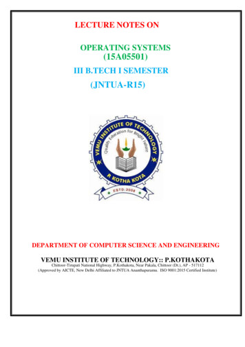
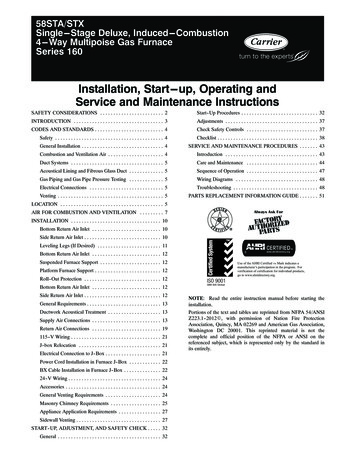
5.1[130.5]2 1/16[51.6]1.7[43.5]FRONT OF CASINGØ7/8[22.2]ACCESSORY (2)1 15/16[49.2]5 15/16[150.7]5 1/2[140.3]8 7/16[213.5]9 7/8[250.7]27 3/4[704.7]2 5/163 7/16 [59][86.8]5 7/8[148.5]TOP OF CASINGØ7/8[22.2]JUNCTION BOXLOCATIONAIR FLOWØ7/8[22.2]ACCESSORYØ1/2[12.7]THERMOSTAT WIRE ENTRY5 7/8[148.5]AIR FLOW5 7/16[138.5]AB6 13/16[172.3]5 5/8[143.3]AIR FLOW1 15/16[49.2]19[481.7]OUTLETTOP OF CASING4 13/16[122.2]9 9/16[243.3]27 3/4[704.7]Ø1 3/4[44.5]GAS ENTRY29 9/16[750.7]33 1/4[843.9]Ø1/2[12.7]THERMOSTAT WIRE ENTRYØ1 3/4[44.5]GAS ENTRYØ7/8[22.2]ACCESSORY6.1[155.7]DBOTTOM RETURNWIDTHKNOCK OUTS FORVENTING(5PLACES)3/4[19.1]7 13/169 11/16[197.8][245.4]11 7/16[290.7]Ø7/8[22.2]J.BOX 1.6[549.5]BOTTOM INLET28.39[721.2]29[736.9]8 5/8[219]58STFRONT OF CASINGC22 1/16[560]SIDE INLET(BOTH SIDES)14 7/8[337.3](BOTH SIDES)1 1/4[31.8]1[25.4]A10290NOTES:1. Two additional 7/8 ---in. (22 mm) diameter holes are located in the top plate.2. Minimum return ---air openings at furnace, based on metal duct. If flex duct is used, see flex duct manufacturer’s recommendations for equivalent diameters.(a.) For 800 CFM ---16 ---in. (406 mm) round or 14 1/2 x 12 ---in. (368 x 305 mm) rectangle.(b.) For 1200 CFM ---20 ---in. (508 mm) round or 14 1/2 x 19 1/2 ---in. (368 x 495 mm) rectangle.(c.) For 1600 CFM ---22 ---in. (559 mm) round or 14 1/2 x 22 1/16 ---in. (368 x 560mm) rectangle.(d.) For airflow requirements above 1800 CFM, see Air Delivery table in Product Data literature for specific use of single side inlets. The use of both sideinlets, a combination of 1 side and the bottom, or the bottom only will ensure adequate return air openings for airflow requirements above 1800 CFM.FURNACE 16/048135135---22/066135155---20/06015514--- 3/16 (360)14--- 3/16 (360)14--- 3/16 (360)14--- 3/16 (360)17--- 1/2 (445)17--- 1/2 (445)21 (533)21 (533)17--- 1/2 (445)21 (533)21 (533)21 (533)24--- 1/2 (622)24--- 1/2 (622)12--- 9/16 (319)12--- 9/16 (319)12--- 9/16 (319)12--- 9/16 (319)15--- 7/8 (403)15--- 7/8 (403)19--- 3/8 (492)19--- 3/8 (492)15--- 7/8 (403)19--- 3/8 (492)19--- 3/8 (492)19--- 3/8 (492)22--- 7/8 (581)22--- 7/8 (581)CTOP & BOTTOMFLUE COLLARLOCATION9--- 5/16 (237)9--- 5/16 (237)9--- 5/16 (237)9--- 5/16 (237)11--- 9/16 (294)11--- 9/16 (294)13--- 5/16 (338)13--- 5/16 (338)11--- 9/16 (294)13--- 5/16 (338)13--- 5/16 (338)13--- 5/16 (338)15--- 1/16 (383)15--- 1/16 (383)DBOTTOMINLET WIDTHVENTCONNECTIONSIZESHIP WTLB (KG)12--- 11/16 (322)12--- 11/16 (322)12--- 11/16 (322)12--- 11/16 (322)16 (406)16 (406)19--- 1/2 (495)19--- 1/2 (495)16 (406)19--- 1/2 (495)19--- 1/2 (495)19--- 1/2 (495)23 (584)23 (584)4 (102)4 (102)4 (102)4 (102)4 (102)4 (102)4 (102)4 (102)4 (102)4 (102)4 (102)4 (102)*4 (102)*4 (102)*104 (47)107 (49)111 (50)115 (52)126 (57)127 (58)140 (64)146 (66)135 (61)146 (66)152 (69)149 (68)163 (74)170 (77)*135 and 155 size furnaces require a 5 or 6 ---in. (127 or 152 mm) vent. Use a vent adapter between furnace and vent stack. See Installation Instructions forcomplete installation requirements.Fig. 1 --- Dimensional Drawing3
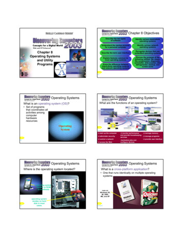
58STFig. 2 --- Clearances to Combustibles80/ 27 C60/ 16 CA10269chamber and/or heat exchanger. The furnace is factory--shippedfor use with natural gas. This furnace is not approved forinstallation in mobile homes, recreational vehicles, or outdoors.This furnace is designed for minimum continuous return--airtemperature of 60 F (16 C) db or intermittent operation down to55 F (13 C) db such as when used with a night setbackthermostat. Return--air temperature must not exceed 80 F (27 C)db. Failure to follow these return--air temperature limits mayaffect reliability of heat exchangers, motors, and controls. (SeeFig. 3.)For accessory installation details, refer to the applicableinstruction literature.NOTE: Remove all shipping brackets and materials beforeoperating the furnace.CODES AND STANDARDSFig. 3 --- Return Air TemperatureFollow all national and local codes and standards in additionto these instructions. The installation must comply withregulations of the serving gas supplier, local building, heating,plumbing, and other codes. In absence of local codes, theinstallation must comply with the national codes listed below andall authorities having jurisdiction. In the United States , follow allcodes and standards for the following:A06745INTRODUCTIONThis 4--way multipoise Category I fan--assisted furnace is CSAdesign--certified. A Category I fan--assisted furnace is anappliance equipped with an integral mechanical means to eitherdraw or force products of combustion through the combustionStep 1 —Safety4
National Fuel Gas Code (NFGC) NFPA 54--2012/ANSI Z223.1--2012 and the Installation Standards, WarmAir Heating and Air Conditioning Systems ANSI/NFPA 90B2.Step 2 —General InstallationS Current edition of the NFGC and the NFPA 90B. Forcopies, contact the National Fire Protection AssociationInc., Batterymarch Park, Quincy, MA 02269;(www.NFPA.org) or for only the NFGC, contact theAmerican Gas Association, 400 N. Capitol Street,N.W., Washington, DC 20001 (www.AGA.org).3.Step 3 —Combustion and Ventilation AirS Section 9.3 of the NFGC, NFPA 54 / ANSI4.Z223.1--2012 Air for Combustion and VentilationStep 4 —Duct SystemsS Air Conditioning Contractors Association (ACCA)5.Manual D, Sheet Metal and Air Conditioning Contractors National Association (SMACNA), or AmericanSociety of Heating, Refrigeration, and Air Conditioning Engineers (ASHRAE) 2001 Fundamentals Handbook Chapter 34 or 2000 HVAC Systems and Equipment Handbook Chapters 9 and 16.6.Step 5 —Acoustical Lining and Fibrous GlassDuctS Current edition of SMACNA and NFPA 90B as tested7.ANY WIRE CONNECTED TO THE CONTROL PRIORTODISCHARGINGYOURBODY’SELECTROSTATIC CHARGE TO GROUND.Firmly touch the clean, unpainted, metal surface of the furnace chassis which is close to the control. Tools held in aperson’s hand during grounding will be satisfactorily discharged.After touching the chassis, you may proceed to service thecontrol or connecting wires as long as you do nothing torecharge your body with static electricity (for example;DO NOT move or shuffle your feet, do not touch ungrounded objects, etc.).If you touch ungrounded objects (and recharge your bodywith static electricity), firmly touch a clean, unpaintedmetal surface of the furnace again before touching controlor wires.Use this procedure for installed and uninstalled (ungrounded) furnaces.Before removing a new control from its container, discharge your body’s electrostatic charge to ground to protect the control from damage. If the control is to be installed in a furnace, follow items 1 through 4 beforebringing the control or yourself in contact with the furnace. Put all used and new controls into containers beforetouching ungrounded objects.An ESD service kit (available from commercial sources)may also be used to prevent ESD damage.LOCATIONby UL Standard 181 for Class I Rigid Air DuctsStep 6 —Gas Piping and Gas Pipe PressureTestingS NFGC; NFPA 54 / ANSI Z223.1--2012 chapters 5, 6, 7!CARBON MONOXIDE POISONING AND UNITDAMAGE HAZARDand 8 and National Plumbing CodesStep 7 —Electrical ConnectionsS National Electrical Code (NEC) ANSI/NFPA 70--2011Step 8 —VentingS NFGC NFPA 54 / ANSI Z223.1--2012; chapters 12Failure to follow this warning could result in personalinjury or death, and unit component damage.Corrosive or contaminated air may cause failure of partscontaining flue gas, which could leak into the living space.Air for combustion must not be contaminated by halogencompounds, which include fluoride, chloride, bromide, andiodide. These elements can corrode heat exchangers andshorten furnace life. Air contaminants are found in aerosolsprays, detergents, bleaches, cleaning solvents, salts, airfresheners, and other household products. Do not installfurnace in a corrosive or contaminated atmosphere. Makesure all combustion and circulating air requirements are met,in addition to all local codes and ordinances.and 13ELECTROSTATIC DISCHARGE (ESD)PRECAUTIONS PROCEDURE!WARNINGCAUTIONFURNACE RELIABILITY HAZARDGENERALThis multipoise furnace is shipped in packaged configuration.Some assembly and modifications are required when used in anyof the four applications shown in Fig. 4.This furnace must:Failure to follow this caution may result in furnacecomponent damage.Electrostatic discharge can affect electronic components.Follow the Electrostatic Discharge Precautions Procedurelisted below during furnace installation and servicing toprotect the furnace electronic control. Precautions willprevent electrostatic discharges from personnel and handtools which are held during the procedure. Theseprecautions will help to avoid exposing the control toelectrostatic discharge by putting the furnace, the control,and the person at the same electrostatic potential.1. Disconnect all power to the furnace. Multiple disconnectsmay be required. DO NOT TOUCH THE CONTROL OR5Sbe installed so the electrical components are protectedfrom water.Snot be installed directly on any combustible materialother than wood flooring for upflow applications.Downflow installations require use of a factory--approved floor base or coil assembly when installed oncombustible materials or wood flooring. (Refer toSAFETY CONSIDERATIONS).58STS
THE BLOWER ISLOCATED BELOW THEBURNER SECTION, ANDCONDITIONED AIR ISDISCHARGED UPWARD.58STTHE BLOWER IS LOCATEDTO THE RIGHT OF THEBURNER SECTION, ANDAIR CONDITIONED AIR ISDISCHARGED TO THE LEFT.THE BLOWER ISLOCATED TO THE LEFTOF THE BURNER SECTION,AND CONDITIONED AIR ISDISCHARGED TO THE RIGHT.THE BLOWER ISLOCATED ABOVE THEBURNER SECTION, ANDCONDITIONED AIR ISDISCHARGED DOWNWARDA02097Fig. 4 --- Multipoise OrientationsSbe located as close to the chimney or vent and attachedto an air distribution system. Refer to Air Ducts section.Sbe provided ample space for servicing and cleaning.Always comply with minimum fire protection clearances shown on the furnace clearance to combustiblelabel.SThe following types of furnace installations may require OUTDOOR AIR for combustion due to chemicalexposures:SSSSSCommercial buildingsSSSSSSPrinting inks, paint removers, varnishes, etc.Hydrochloric acidCements and gluesAntistatic fabric softeners for clothes dryersMasonry acid washing materialsAll fuel--burning equipment must be supplied with air for fuelcombustion. Sufficient air must be provided to avoid negativepressure in the equipment room or space. A positive seal must bemade between the furnace cabinet and the return--air duct toprevent pulling air from the burner area and from draft safeguardopening.Buildings with indoor poolsLaundry roomsHobby or craft rooms, and!Chemical storage areasIf air is exposed to the following substances, it should not be usedfor combustion air, and outdoor air may be required forcombustion:SSSSSSSCleaning solvents (such as perchloroethylene)WARNINGFIRE AND EXPLOSION HAZARDFailure to follow this warning could result in personalinjury, death, and/or property damage.Permanent wave solutionsWhen the furnace is installed in a residential garage, theburners and ignition sources must be located at least 18inches above the floor. The furnace must be located orprotected to avoid damage by vehicles. When the furnace isinstalled in a public garage, airplane hangar, or otherbuilding having a hazardous atmosphere, the furnace mustbe installed in accordance with the NFGC. (See Fig. 5.)Chlorinated waxes and cleanersChlorine based swimming pool chemicalsWater softening chemicalsDe--icing salts or chemicalsCarbon tetrachlorideHalogen type refrigerants6
!CAUTION!WARNINGFIRE HAZARDPERSONAL INJURY AND/OR PROPERTYDAMAGE HAZARDFailure to follow this warning could result in personalinjury, death and/or property damage.Failure to follow this caution may result in furnacecomponent damage.Do not install the furnace on its back or hang furnace withcontrol compartment facing downward. Safety controloperation will be adversely affected. Never connectreturn--air ducts to the back of the furnace. (See Fig. 6.)This gas furnace may be used for heating buildings underconstruction provided that:--The furnace is permanently installed with all electricalwiring, piping, venting and ducting installed according tothese installation instructions. A return air duct is provided,sealed to the furnace casing, and terminated outside thespace containing the furnace. This prevents a negativepressure condition as created by the circulating air blower,causing a flame rollout and/or drawing combustionproducts into the structure.58ST--The furnace is controlled by a thermostat. It may not behot wired to provide heat continuously to the structurewithout thermostatic control.--Clean outside air is provided for combustion. This is tominimize the corrosive effects of adhesives, sealers andother construction materials. It also prevents theentrainment of drywall dust into combustion air, which cancause fouling and plugging of furnace components.Fig. 6 --- Prohibit Installation on Back--The temperature of the return air to the furnace ismaintained between 55 F (13 C) and 80 F (27 C), withno evening setback or shutdown. The use of the furnacewhile the structure is under construction is deemed to beintermittent operation per our installation instructions.A02054LOCATION RELATIVE TO COOLING EQUIPMENTThe cooling coil must be installed parallel with, or on thedownstream side of the unit to avoid condensation in the heatexchangers. When installed parallel with the furnace, dampers orother flow control must prevent chilled air from entering thefurnace. If the dampers are manually operated, they must beequipped with means to prevent operation of either unit unlessthe damper is in the full--heat or full--cool position.--The air temperature rise is within the rated rise range onthe furnace rating plate, and the gas input rate has been setto the nameplate value.--The filters used to clean the circulating air during theconstruction process must be either changed or thoroughlycleaned prior to occupancy.AIR FOR COMBUSTION ANDVENTILATION--The furnace, ductwork and filters are cleaned as necessaryto remove drywall dust and construction debris from allHVAC system components after construction is completed.Provisions for adequate combustion, ventilation, and dilution airmust be provided in accordance with:--Verify proper furnace operating conditions includingignition, gas input rate, air temperature rise, and ventingaccording to these installation instructions.SSection 9.3 of the NFPA 54 / ANSI Z223.1--2012, Airfor Combustion and Ventilation, and applicable provisions of the local building codes.!CAUTIONFURNACE CORROSION HAZARDFailure to follow this caution may result in furnace damage.Air for combustion must not be contaminated by halogencompounds, which include fluoride, chloride, bromide, andiodide. These elements can corrode heat exchangers andshorten furnace life. Air contaminants are found in aerosolsprays, detergents, bleaches, cleaning solvents, salts, airfresheners, and other household products.18-IN. (457.2 mm)MINIMUM TO BURNERSFig. 5 --- Installation in a GarageA930447
f. Size openings and ducts per Fig. 7 and Table 1.g. TWO HORIZONTAL DUCTS require 1 sq./in. of freearea per 2,000 Btuh (1,100 mm2/kW) of combinedinput for all gas appliances in the space per Fig. 7 andTable 1.h. TWO OPENINGS OR VERTICAL DUCTS require 1sq./in. of free area per 4,000 Btuh (550 mm2/kW) forcombined input of all gas appliances in the space perFig. 7 and Table 1.3. ONE OUTDOOR OPENING requires:a. 1 square inch of free area per 3,000 Btuh (734mm2/kW) for combined input of all gas appliances inthe space per Table 1 andb. Not less than the sum of the areas of all vent connectors in the space.The opening shall commence within 12 in. (300 mm) of theceiling. Appliances in the space shall have clearances of at least 1in. (25 mm) from the sides and back and 6 in. (150 mm) from thefront. The opening shall directly communicate with the outdoorsor shall communicate through a vertical or horizontal duct to theoutdoors or spaces (crawl or attic) that freely communicate withthe outdoors.Indoor Combustion Air NFPA & AGAStandard and Known--Air--Infiltration Rate MethodsIndoor air is permitted for combustion, ventilation, and dilution,if the Standard or Known--Air--Infiltration Method is used.WARNING!CARBON MONOXIDE POISONING HAZARDFailure to follow this warning could result in personalinjury or death.58STThe operation of exhaust fans, kitchen ventilation fans,clothes dryers, attic exhaust fans or fireplaces could create aNEGATIVE PRESSURE CONDITION at the furnace.Make--up air MUST be provided for the ventilation devices,in addition to that required by the furnace. Refer to CarbonMonoxide Poisoning Hazard warning in venting section ofthese instructions to determine if an adequate amount ofmake--up air is available.The requirements for combustion and ventilation air dependupon whether or not the furnace is located in a space having avolume of at least 50 cu/ft. per 1,000 Btuh input rating for all gasappliances installed in the space.SSpaces having less than 50 cu/ft. per 1,000 Btuh require the OUTDOOR COMBUSTION AIRMETHOD.Spaces having at least 50 cu/ft. per 1,000 Btuh may usethe INDOOR COMBUSTION AIR, STANDARD orKNOWN AIR INFILTRATION METHOD.Outdoor Combustion Air Method1. Provide the space with sufficient air for proper combustion, ventilation, and dilution of flue gases using permanent horizontal or vertical duct(s) or opening(s) directlycommunicating with the outdoors or spaces that freelycommunicate with the outdoors.2. Fig. 7 illustrates how to provide TWO OUTDOOROPENINGS, one inlet and one outlet combustion andventilation air opening, to the outdoors.e. One opening MUST commence within 12 in. (300mm) of the ceiling and the second opening MUSTcommence within 12 in. (300 mm) of the floor.S!WARNINGCARBON MONOXIDE POISONING HAZARDFailure to follow this warning could result in death and/orpersonal injury.Many homes require air to be supplied from outdoors forfurnace combustion, ventilation, and dilution of flue gases.The furnace combustion air supply must be provided inaccordance with this instruction manual.Table 1—Minimum Free Area Required for Each Combustion Air Opening of Duct to 0132,000154,000FURNACE110,00066,00088,000TWO HORIZONTAL DUCTSSINGLE DUCT OR OPENING(1 SQ. IN./2,000 BTUH)(1,100 SQ. MM/KW)Free Area of OpenRound Ducting and DuctDia.Sq. In. (Sq. mm)In. (mm)22 (14194)6 (152)33 (21290)7 (178)44 (28387)8 (203)55 (35484)9 (229)66 (42580)10 (254)77 (49677)10 (254)(1 SQ. IN./3,000 BTUH)(734 SQ. MM/KW)Free Area of OpenRound Ducting and DuctDia.Sq. In. (Sq. mm)In. (mm)14.7 (9484)5 (127)22.0 (14193)6 (152)29.3 (18903)7 (178)36.7 (23677)7 (178)44 .0 (28387)8 (203)51.3 (33096)9 (229) WATER HEATER30,00040,00030,000 EXAMPLES: Determining Free AreaTOTAL INPUT(140,000 divided by 4,000) (106,000 divided by 3,000) (118,000 divided by 2,000) 8TWO OPENINGS OR VERTICALDUCTS(1 SQ. IN./4,000 BTUH)(550 SQ. MM/KW)Free Area of OpenRound Ducting and DuctDia.Sq. In. (Sq. mm)In. (mm)11 (7096)4 (102)16.5 (10645)5 (127)22 (14193)6 (152)27.5 (17742)6 (152)33 (21290)7 (178)38.5 (24839)8 (203)35.0 Sq. In. for each two Vertical Ducts or Openings35.3 Sq. In. for a Single Duct or Opening59.0 Sq. In. for each of two Horizontal Ducts
Table 2—Minimum Space Volumes for 100% Combustion, Ventilation, and Dilution from IndoorsFAN-ASSISTED TOTAL(1,000’S BTUH GAS INPUT RATE)3040501101321541,750(49.5)6688Space Volume Ft3 (M3)1,1001,6502,200(31.1
58STA/STX Single---Stage Deluxe, Induced---Combustion 4---Way Multipoise Gas Furnace Series 160 Installation, Start---up, Operating and Service and Maintenance Instructions