Transcription
58MEBDeluxe 4---Way MultipoiseFixed---Capacity Condensing Gas FurnaceSizes 040---120, Series 100 & 110Installation, Start---up andOperating InstructionsVisit www.Carrier.comNOTE: Read the entire instruction manual before startingthe installation.NOTE: This furnace can be installed as a (2-pipe) direct ventor (1-pipe) non-direct vent condensing gas furnace.Special Venting Requirements for Installations in CanadaConsignes spéciales pour l’installation de ventillation au CanadaInstallation in Canada must conform to the requirements of CSAB149 code. Vent systems must be composed of pipe, fittings,cements, and primers listed to ULC S636. The special ventfittings and accessory concentric vent termination kits andaccessory external drain trap have been certified to ULC S636 foruse with those IPEX PVC vent components which have beencertified to this standard. In Canada, the primer and cement mustbe of the same manufacturer as the vent system -- IPEX System636, PVC/CPVC Primer, Purple Violet for Flue Gas Venting andIPEX System 636(1)t, PVC Cement for Flue Gas Venting, ratedClass IIA, 65 deg C. must be used with this venting system -- donot mix primers and cements from one manufacturer with a ventsystem from a different manufacturer. Follow the manufacturer’sinstructions in the use of primer and cement and never use primeror cement beyond its expiration date.The safe operation, as defined by ULC S636, of the vent systemis based on following these installation instructions, the ventsystem manufacturer’s installation instructions, and proper use ofprimer and cement. All fire stop and roof flashing used with thissystem must be UL listed material. Acceptability under Canadianstandard CSA B149 is dependent upon full compliance with allinstallation instructions. Under this standard, it is recommendedthat the vent system be checked once a year by qualified servicepersonnel.The authority having jurisdiction (gas inspection authority,municipal building department, fire department, etc) should beconsulted before installation to determine the need to obtain apermit.L’installation faite au Canada doit se conformer aux exigences ducode CSA B149. Ce systême de ventillation doit se composer detuyaux, raccords, ciments et apprêts conformes au ULC S636. Latuyauterie de ventillation des gaz, ses accessoires, le terminalconcentrique mural ainsi que l’ensemble du drain de condensatextérieur ont été certifiés ULCS 636 pour l’application descomposantes IPEX PVC qui sont certifiées à ce standard. AuCanada l’apprêt et le ciment doivent être du même manufacturierque le systême de ventillation -- IPEX Système 636, ApprêtPVC/CPVC. Mauve Violette pour conduit en évacuation des gazet IPEX Système 636(1)t, ciment pour PVC pour conduit enévacuation des gaz, évalué CLASSE IIA, 65 deg. C. doit ëtreutilisé avec ce systèeme d’évacuation -- ne pas mélanger l’apprêtet le ciment d’un manufacturier avec le systême de ventillationd’un autre manufacturier. Bien suivre les indications dumanufacturier lors de l’utilisation de l’apprêt et du ciment et nepas utiliser ceux--ci si la date d’expiration est atteinte.L’opération sécuritaire, tel que définit par ULC S636, du systèmede ventilation est basé sur les instructions d’installation suivantes,ainsi que l’usage approprié de l’apprêt et ciment. Tout arrët feu etsolin de toit utilisés avec ce système doivent être des matériauxlistés UL. L’acceptation du standard Canadien CSA B419 estdirectement relié à l’installation conforme aux instructions ci-haut mentionnées. Le standard Canadien recommande l’inspection par un personel qualifié et ce, une fois par année.Les autoritées ayant juridiction (inspecteurs de gas, inspecteursen bâtiments, département des incendies, etc) devraient êtreconsultées avant l’installation afin de déterminer si un permis estrequis.(1) System 636 is a trademark of IPEX Inc.
Required Notice for Massachusetts InstallationsIMPORTANTThe Commonwealth of Massachusetts requires compliance with regulation 248 CMR as follows:5.08: Modifications to NFPA--54, Chapter 102) Revise 10.8.3 by adding the following additional requirements:a. For all side wall horizontally vented gas fueled equipment installed in every dwelling, building or structure usedin whole or in part for residential purposes, including those owned or operated by the Commonwealth and wherethe side wall exhaust vent termination is less than seven (7) feet above finished grade in the area of the venting,including but not limited to decks and porches, the following requirements shall be satisfied:1. INSTALLATION OF CARBON MONOXIDE DETECTORS. At the time of installation of the side wall horizontal ventedgas fueled equipment, the installing plumber or gasfitter shall observe that a hard wired carbon monoxide detector with analarm and battery back--up is installed on the floor level where the gas equipment is to be installed. In addition, theinstalling plumber or gasfitter shall observe that a battery operated or hard wired carbon monoxide detector with an alarm isinstalled on each additional level of the dwelling, building or structure served by the side wall horizontal vented gas fueledequipment. It shall be the responsibility of the property owner to secure the services of qualified licensed professionals forthe installation of hard wired carbon monoxide detectorsa. In the event that the side wall horizontally vented gas fueled equipment is installed in a crawl space or an attic, the hardwired carbon monoxide detector with alarm and battery back--up may be installed on the next adjacent floor level.b. In the event that the requirements of this subdivision can not be met at the time of completion of installation, the ownershall have a period of thirty (30) days to comply with the above requirements; provided, however, that during said thirty(30) day period, a battery operated carbon monoxide detector with an alarm shall be installed.2. APPROVED CARBON MONOXIDE DETECTORS. Each carbon monoxide detector as required in accordance with theabove provisions shall comply with NFPA 720 and be ANSI/UL 2034 listed and IAS certified.3. SIGNAGE. A metal or plastic identification plate shall be permanently mounted to the exterior of the building at aminimum height of eight (8) feet above grade directly in line with the exhaust vent terminal for the horizontally vented gasfueled heating appliance or equipment. The sign shall read, in print size no less than one--half (1/2) inch in size, ”GASVENT DIRECTLY BELOW. KEEP CLEAR OF ALL OBSTRUCTIONS”.4. INSPECTION. The state or local gas inspector of the side wall horizontally vented gas fueled equipment shall not approvethe installation unless, upon inspection, the inspector observes carbon monoxide detectors and signage installed inaccordance with the provisions of 248 CMR 5.08(2)(a)1 through 4.5. EXEMPTIONS: The following equipment is exempt from 248 CMR 5.08(2)(a)1 through 4:(1.) The equipment listed in Chapter 10 entitled ”Equipment Not Required To Be Vented” in the most current edition ofNFPA 54 as adopted by the Board; and(2.) Product Approved side wall horizontally vented gas fueled equipment installed in a room or structure separate fromthe dwelling, building or structure used in whole or in part for residential purposes.c. MANUFACTURER REQUIREMENTS -- GAS EQUIPMENT VENTING SYSTEM PROVIDED. When themanufacturer of Product Approved side wall horizontally vented gas equipment provides a venting system designor venting system components with the equipment, the instructions provided by the manufacturer for installationof the equipment and the venting system shall include:1. Detailed instructions for the installation of the venting system design or the venting system components; and2. A complete parts list for the venting system design or venting system.d. MANUFACTURER REQUIREMENTS -- GAS EQUIPMENT VENTING SYSTEM NOT PROVIDED. Whenthe manufacturer of a Product Approved side wall horizontally vented gas fueled equipment does not provide theparts for venting the flue gases, but identifies “special venting systems”, the following requirements shall besatisfied by the manufacturer:1. The referenced “special venting system” instructions shall be included with the appliance or equipment installationinstructions; and2. The “special venting systems” shall be Product Approved by the Board, and the instructions for that system shall include aparts list and detailed installation instructions.e. A copy of all installation instructions for all Product Approved side wall horizontally vented gas fueledequipment, all venting instructions, all parts lists for venting instructions, and/or all venting design instructionsshall remain with the appliance or equipment at the completion of the installation.For questions regarding these requirements, please contact the Commonwealth of Massachusetts Board of State Examiners of Plumbersand Gas Fitters, 239 Causeway Street, Boston, MA 02114. 617--727--9952.-- 2 --
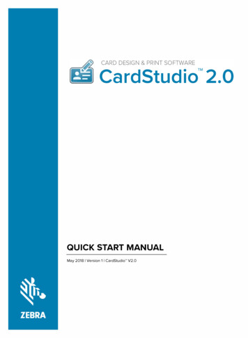
SAFETY nt,alteration,service,maintenance, or use can cause explosion, fire, electrical shock, orother conditions which may cause death, personal injury, orproperty damage. Consult a qualified installer, service agency, oryour distributor or branch for information or assistance. Thequalified installer or agency must use factory--authorized kits oraccessories when modifying this product. Refer to the individualinstructions packaged with the kits or accessories when installing.Follow all safety codes. Wear safety glasses, protective clothing,and work gloves. Have a fire extinguisher available. Read theseinstructions thoroughly and follow all warnings or cautionsinclude in literature and attached to the unit. Consult localbuilding codes, the current editions of the National Fuel GasCode (NFGC) NFPA 54/ANSI Z223.1 and the National ElectricalCode (NEC) NFPA 70.In Canada, refer to the current editions of the National Standardsof Canada CAN/CSA--B149.1 and .2 Natural Gas and PropaneInstallation Codes, and Canadian Electrical Code CSA RFLOWAIRFLOWAIRFLOWA93041Fig. 1 -- Multipoise OrientationTABLE OF CONTENTSRecognize safety information. This is the safety--alert symbol .When you see this symbol on the unit and in instructions ormanuals, be alert to the potential for personal injury.Understand the signal words DANGER, WARNING, andCAUTION. These words are used with the safety--alert symbol.DANGER identifies the most serious hazards which will result insevere personal injury or death. WARNING signifies hazardswhich could result in personal injury or death. CAUTION isused to identify unsafe practices which may result in minorpersonal injury or product and property damage. NOTE is usedto highlight suggestions which will result in enhancedinstallation, reliability, or operation.SAFETY CONSIDERATIONS . . . . . . . . . . . . . . . . . . . . . . . . . . 3CODES AND STANDARDS . . . . . . . . . . . . . . . . . . . . . . . . . . . 5ELECTROSTATIC DISCHARGE (ESD) PRECAUTIONS . . . 7INTRODUCTION . . . . . . . . . . . . . . . . . . . . . . . . . . . . . . . . . . . . 8APPLICATIONS . . . . . . . . . . . . . . . . . . . . . . . . . . . . . . . . . . . . . 8General . . . . . . . . . . . . . . . . . . . . . . . . . . . . . . . . . . . . . . . . . . . 8Upflow Applications . . . . . . . . . . . . . . . . . . . . . . . . . . . . . . . . . 8Downflow Applications . . . . . . . . . . . . . . . . . . . . . . . . . . . . . 10Horizontal Left (Supply-Air Discharge)Applications . . . . . . . . . . . . . . . . . . . . . . . . . . . . . . . . . . . . . . 12Horizontal Right (Supply-Air Discharge)Applications . . . . . . . . . . . . . . . . . . . . . . . . . . . . . . . . . . . . . . 13LOCATION . . . . . . . . . . . . . . . . . . . . . . . . . . . . . . . . . . . . . . . . 16General . . . . . . . . . . . . . . . . . . . . . . . . . . . . . . . . . . . . . . . . . . 16Furnace Location Relative to Cooling Equipment . . . . . . . . . 17Hazardous Locations . . . . . . . . . . . . . . . . . . . . . . . . . . . . . . . 18Furnace Location and Application . . . . . . . . . . . . . . . . . . . . . 18AIR FOR COMBUSTION AND VENTILATION . . . . . . . . . . 18INSTALLATION . . . . . . . . . . . . . . . . . . . . . . . . . . . . . . . . . . . . 21Leveling Legs (If Desired) . . . . . . . . . . . . . . . . . . . . . . . . . . . 21Installation in Upflow and Downflow Applications . . . . . . . 21Installation in Horizontal Applications . . . . . . . . . . . . . . . . . 22Air Ducts . . . . . . . . . . . . . . . . . . . . . . . . . . . . . . . . . . . . . . . . . 23Filter Arrangement . . . . . . . . . . . . . . . . . . . . . . . . . . . . . . . . . 25Bottom Closure Panel . . . . . . . . . . . . . . . . . . . . . . . . . . . . . . . 25Gas Piping . . . . . . . . . . . . . . . . . . . . . . . . . . . . . . . . . . . . . . . . 25Electrical Connections . . . . . . . . . . . . . . . . . . . . . . . . . . . . . . 27Removal of Existing Furnaces fromCommon Vent Systems . . . . . . . . . . . . . . . . . . . . . . . . . . . . . . 30Combustion Air and Vent Pipe Systems . . . . . . . . . . . . . . . . . 30Condensate Drain . . . . . . . . . . . . . . . . . . . . . . . . . . . . . . . . . . 46START-UP, ADJUSTMENTS, AND SAFETY CHECK . . . . . 47General . . . . . . . . . . . . . . . . . . . . . . . . . . . . . . . . . . . . . . . . . . 47Prime Condensate Trap With Water . . . . . . . . . . . . . . . . . . . . 47Purge Gas Lines . . . . . . . . . . . . . . . . . . . . . . . . . . . . . . . . . . . 47Sequence of Operation . . . . . . . . . . . . . . . . . . . . . . . . . . . . . . 48Adjustments . . . . . . . . . . . . . . . . . . . . . . . . . . . . . . . . . . . . . . 54Check Safety Controls . . . . . . . . . . . . . . . . . . . . . . . . . . . . . . 57Checklist . . . . . . . . . . . . . . . . . . . . . . . . . . . . . . . . . . . . . . . . . 59!CAUTIONUNIT RELIABILITY HAZARDFailure to follow this caution may result in unit componentdamage.Application of this furnace should be indoors with specialattention given to vent sizing and material, gas input rate, airtemperature rise, unit leveling, and unit sizing.!CAUTIONFIRE, EXPLOSION, ELECTRICAL SHOCK ANDCARBON MONOXIDE POISONING HAZARDFailure to follow this warning could result in electrical shock,fire, personal injury, or death.Improper installation, adjustment, alteration, service,maintenance, or use can cause carbon monoxide poisoning,explosion, fire, electrical shock, or other conditions whichmay cause personal injury or property damage. Consult aqualified installer, service agency, local gas supplier, or yourdistributor or branch for information or assistance. Thequalified installer or agency must use only factory-authorizedand listed kits or accessories when modifying this product.!CAUTIONCUT HAZARDFailure to follow this caution may result in personal injury.Sheet metal parts may have sharp edges or burrs. Use care andwear appropriate protective clothing and gloves whenhandling parts.-- 3 --
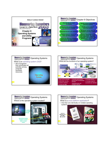
S The furnace is permanently installed with all electrical wiring,piping, air filters, venting and ducting installed according tothese installation instructions. A return air duct is provided,sealed to the furnace casing, and terminated outside the spacecontaining the furnace. This prevents a negative pressurecondition as created by the circulating air blower, causing aflame rollout and/or drawing combustion products intothe structure.S The furnace is controlled by a thermostat. It may not be “hotwired” to provide heat continuously to the structure with outthermostatic control.S Clean outside air is provided for combustion. This is tominimize the corrosive effects of adhesives, sealers and otherconstruction materials. It also prevents the entrainment ofdrywall dust into combustion air, which can cause fouling andplugging of furnace components.S The temperature of the return air to the furnace is maintainedbetween 55 F (13 C) and 80 F (27 C), with no eveningsetback or shutdown. The use of the furnace while the structureis under construction is deemed to be intermittent operation perour installation instructions.S The air temperature rise is within the rated rise range on thefurnace rating plate, and the firing rate has been set to thenameplate value.S The filters used to clean the circulating air during theconstruction process must be either changed or thoroughlycleaned prior to occupancy.S The furnace, ductwork and filters are cleaned as necessary toremove drywall dust and construction debris from all HVACsystem components after construction is completed.S After construction is complete, verify furnace operatingconditions including ignition, input rate, temperature rise andventing, according to the manufacturer’s instructions.The furnace shall be installed so that the electrical componentsare protected from water.These furnaces are shipped with the following materials to assistin proper furnace installation. These materials are shipped in themain blower compartment.The 58MEB Multipoise Condensing Gas-Fired Furnaces are CSA(formerly AGA and CGA) design-certified for natural andpropane gases (see furnace rating plate) and for installation inalcoves, attics, basements, closets, utility rooms, crawlspaces, andgarages. The furnace is factory-shipped for use with natural gas.A CSA listed gas conversion kit is required to convert furnace foruse with propane gas.See Fig. 3 for required clearances to combustibles.Maintain a 1-in. (25.4 mm) clearance from combustible materialsto supply air ductwork for a distance of 36 inches (914 mm)horizontally from the furnace. See NFPA 90B or local code forfurther requirements.These furnaces SHALL NOT be installed directly on carpeting,tile, or any other combustible material other than wood flooring.In downflow installations, factory accessory floor base MUST beused when installed on combustible materials and wood flooring.Special base is not required when this furnace is installed onmanufacturer’s Coil Assembly Part No. CAP, CAR or CNPV,CNRV, or when Coil Box Part No. KCAKC is used.The 58MEB 040 through 120 size units are CSA design-certifiedfor use in manufactured (mobile) homes when installed as a2-pipe (direct vent) furnace and a factory accessory conversionkit is used. These furnaces are suitable for installation in astructure built on site or a manufactured building completed atfinal site. The design of this furnace line is NOT CSAdesign-certified for installation in recreation vehicles or outdoors.This furnace is designed for continuous return-air minimumtemperature of 60 F (16 C)db or intermittent operation down to55 F (13 C) db such as when used with a night setbackthermometer. Return-air temperature must not exceed 80 F (27 C) db. Failure to follow these return air limits may affectreliability of heat exchangers, motors and controls. (See Fig. 4.)These furnaces are shipped with the drain and pressure tubesconnected for UPFLOW applications. Minor modifications arerequired when used in DOWNFLOW, HORIZONTAL RIGHT, orHORIZONTAL LEFT (supply-air discharge direction)applications as shown in Fig. 1. See details inApplications section.Install this furnace only in a location and position as specified inLOCATION and INSTALLATION sections of these instructions.Always provide adequate combustion and ventilation air asspecified in section Combustion Air and Vent Pipe Systems ofthese instructions to the furnace.Combustion products must be discharged outdoors. Connect thisfurnace to an approved vent system only, as specified in theCombustion Air and Vent piping sections of these instructions.Never test for gas leaks with an open flame. Use a commerciallyavailable soap solution made specifically for detection of leaks tocheck all connections as specified in the GAS PIPING section ofthese instructions.Always install the furnace to operate within the furnace’sintended rise range with a duct system which has an externalstatic pressure within the allowable range as specified in the SETTEMPERATURE RISE section of these instructions. See furnacerating plate.When a furnace is installed so that supply ducts carry aircirculated by the furnace to areas outside the space containing thefurnace, the return air shall also be handled by ducts sealed to thefurnace casing and terminating outside the space containingthe furnace.A gas-fired furnace for installation in a residential garage must beinstalled as specified in the Hazardous Locations section of theseinstructions.The furnace may be used for construction heat provided that thefurnace installation and operation complies with the firstCAUTION in the LOCATION section of these instructions.This gas furnace may be used for construction heat provided that:Installer Packet includes:Installation, Startup, and Operating InstructionsService and Maintenance InstructionsUser’s Information ManualWarranty CertificateLoose Parts Bag includes:QuantityPressure tube extensionCollector Box or condensate trap extension tubeInducer housing drain tube1/2-in CPVC street elbowDrain tube couplingDrain tube coupling grommetGas line grommetVent pipe grommetCombustion-air pipe grommetGas line entry hole filler plugPower entry hole filler plugCondensate trap hole filler plugVent and combustion-air intake hole filler plugCombustion-air pipe perforated disk assemblyInducer Outlet Restrictor . . . . . . . . . . . . . . . . . . . . . . .Vent Pipe Extension 2 in. x 12 in. (51mm x 305mm)* ONLY supplied with some furnaces.-- 4 --1112111111232111*
S CANADA: NSCNGPIC. For a copy, contact Standard Sales,CSA International, 178 Rexdale Boulevard, Etobicoke(Toronto), Ontario, M9W 1R3, Canada.When this furnace is installed with a direct vent (combustion-airand vent) system, a factory accessory termination kit MUST beused. In a direct-vent system, all air for combustion is takendirectly from the outdoor atmosphere and flue gases aredischarged to the outside atmosphere. See furnace and factoryaccessory vent-air intake termination kit instructions forproper installation.Step 3—Combustion and Ventilation AirS US: Section 9.3 of the National Fuel Gas Code NFPA54/ANSIZ223.1--2009, Air for Combustion and VentilationS CANADA: Part 8 of the National Standard of Canada, NaturalGas and Propane Installation Code CSAB149.1--05, VentingSystems and Air Supply for AppliancesCODES AND STANDARDSFor accessory installation details, refer to accessoryinstallation instructions.Follow all national and local codes and standards in additionto these instructions. The installation must comply withregulations of the serving gas supplier, local building, heating,plumbing, and other codes. In absence of local codes, theinstallation must comply with the national codes listed below andall authorities having jurisdiction.In the United States and Canada, follow all codes and standardsfor the following:Step 4—Duct SystemsS US and CANADA: Air Conditioning Contractors Association(ACCA) Manual D, Sheet Metal and Air ConditioningContractors National Association (SMACNA), or AmericanSociety of Heating, Refrigeration, and Air ConditioningEngineers (ASHRAE) 2005 Fundamentals HandbookChapter 35.Step 1—SafetyStep 5—Acoustical Lining and Fibrous Glass DuctS US: National Fuel Gas Code (NFGC) NFPA 54/ANSI Z223.1and the Installation Standards, Warm Air Heating and AirConditioning Systems ANSI/NFPA 90BS CANADA: National Standard of Canada, Natural Gas andPropane Installation Code (NSCNGPIC) CSA B149.1.S US and CANADA: current edition of SMACNA, NFPA 90B astested by UL Standard 181 for Class I Rigid Air DuctsStep 6—Gas Piping and Gas Pipe Pressure TestingS US: NFGC; chapters 5, 6, 7, and 8 and nationalplumbing codesS CANADA: CAN/CSA----B149.1----05 Parts 4, 5, 6, and 9.Step 2—General InstallationIn the state of Massachusetts:S This product must be installed by a licensed plumber orgas fitter.S When flexible connectors are used, the maximum length shallnot exceed 36 inches (914 mm).S When lever type gas shutoffs are used they shall not exceed36 inches (914 mm).S The use of copper tubing for gas piping is not approved by thestate of Massachusetts.S US: NFGC and the NFPA 90B. For copies, contact theNational Fire Protection Association Inc., Batterymarch Park,Quincy, MA 02269; or for only the NFGC contact theAmerican Gas Association, 400 N. Capitol, N.W., WashingtonDC 20001S A manufactured (Mobile) home installation must conform withthe Manufactured Home Construction and Safety Standard,Title 24 CFR, Part 3280, or when this standard is notapplicable, the Standard for Manufactured Home Installation(Manufactured Home Sites, Communities, and Set-Ups),ANSI/NCS A225.1, and/or CAN/CSA-Z240, MH SeriesMobile HomesStep 7—Electrical ConnectionsS US: National Electrical Code (NEC) ANSI/NFPA 70-2008S CANADA: Canadian Electrical Code CSA C22.1-- 5 --
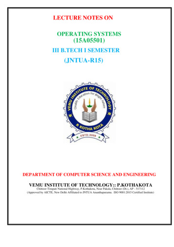
Fig. 2 -- Dimensional DrawingA08321-- 6 --11 4" (32mm)1"(25mm)14 1 2"TYP(368mm)126 15 16" TYP (684mm)23 1 4" TYP (591mm)SIDE INLETSIDE INLET 2-IN. DIA THERMOSTATENTRY(13mm)22 11 16"(576mm)2-IN. VENT CONN(51mm)1 2-IN. DIAGAS CONN(13mm)26 15 16"(684mm)26 1 4"(667mm)24 1 2"(666mm)22 5 16"(567mm)2-IN. COMBUSTIONAIR CONN(51mm) 16"(17mm)EINLETOUTLETD11 16"(17mm)DIMPLE LOCATORSFOR HORIZONTALHANGINGCONDENSATEDRAIN LOCATION(UPFLOW)18 1 4"(464mm)30 2"(775mm)1CONDENSATE DRAINTRAP LOCATION(DOWNFLOW &HORIZONTAL RIGHT)OR ALTERNATE1 2-IN. DIA GAS CONN 16"(21mm)13 16"TYP(14mm)9UNIT SIZE040-12 / 036040060-12 / 036060080-12 / 036080080-16 / 048080100-20 / 060100120-20 / 060120A17-1/2 (445)17-1/2 (445)17-1/2 (445)17-1/2 (445)21 (25.4)24-1/2 (622)D15-7/8 (403)15-7/8 (403)15-7/8 (403)15-7/8 (403)19-3/8 (492)22-7/8 (581)E16 (406)16 (406)16 (406)16 (406)19-1/2 (495)23 (584)NOTES: 1. Minimum return-air openings at furnace, based on metal duct. If flex duct is used,see flex duct manufacturerÕs recommendations for equivalent diameters.2. Minimum return-air opening at furnace:a. For 800 CFM 16-in . (406mm) round or 14 1/ 2 (368mm) x 12-in. (305mm) rectangle.b. For 1200 CFM 20-in . (508mm) round or 14 1/ 2 (368mm) x 19 1/ 2-in. (495mm) rectangle.c. For 1600 CFM 22-in .(559mm) round or 14 1/ 2 (368mm) x 23 1/ 4-in.(591mm) rectangle.d. For airflow requirements above 1800 CFM, see Air Delivery table in Product Dataliterature for specific use of single side inlets. The use of both side inlets, acombination of 1 side and the bottom, or the bottom only will ensure adequatereturn air openings for airflow requirements above 1800 CFM at 0.5“ W.C. ESP.CONDENSATEDRAIN LOCATION(UPFLOW)1133 1 4"TYP(845mm)30 13 16"(783mm)729 11 16" 8-IN. DIA (22mm)TYPACCESSORY(754mm)POWER ENTRY32 5 8"27 5 8"TYP(702mm)CONDENSATE(829mm)DRAIN TRAP27 9 16"LOCATIONTYP(ALTERNATE(700mm)UPFLOW)24 1 2"(622mm)17 5 16"9 7 16"(440mm)TYP(240mm)7 8-IN. DIA (22mm)POWER CONNCONDENSATE DRAINTRAP LOCATION(DOWNFLOW &HORIZONTAL LEFT) 16"(21mm)13AAIRFLOW22 1 4" TYP(565mm)24 3 16"BOTTOM INLET(614mm)SIDE INLET22 11 16"2-IN. VENT CONN1 2-IN. DIATHERMOSTAT ENTRY7 8-IN. DIAPOWER CONN 2-IN. DIAGAS CONN12-IN. COMBUSTIONAIR CONNOUTLET19" (483mm)22 5 16" (567mm)26 1 4" (667mm)26 15 16" (694mm)28 1 2" (724mm) 16" (21mm) 8" (16mm) 16" (17mm) 16" (11mm)1171"(25mm)39 7 8"(1013mm)5 16"(8mm)513
335122-201 REV. B LIT TOPA08435Fig. 3 -- Clearances to Combustibles0ELECTROSTATIC DISCHARGE (ESD)PRECAUTIONS(27º C)!CAUTIONUNIT DAMAGE HAZARDFailure to follow this caution may damage furnacecomponents.60Electrostatic discharge can affect electronic components. Takeprecautions during furnace installation and servicing to protectthe furnace electronic control. Precautions will preventelectrostatic discharges from personnel and hand tools whichare held during the procedure. These precautions will help toavoid exposing the control to electrostatic discharge by puttingthe furnace, the control, and the person at the sameelectrostatic potential.(16º C)A05004Fig. 4 -- Return-Air Temperature-- 7 --
APPLICATIONS3. Disconnect all power to the furnace. Multiple disconnectsmay be required. DO NOT TOUCH THE CONTROL ORANY WIRE CONNECTED TO THE CONTROL PRIORTO DISCHARGING YOUR BODY’S ELECTROSTATICCHARGE TO GROUND.4. Firmly touch the clean, unpainted, metal surface of thefurnace chassis which is close to the control. Tools held ina person’s hand during grounding will besatisfactorily discharged.5. After touching the chassis, you may proceed to service thecontrol or connecting wires as long as you do nothing torecharge your body with static electricity (for example;DO NOT move or shuffle your feet, do not touchungrounded objects, etc.).6. If you touch ungrounded objects (and recharge your bodywith static electricity), firmly touch a clean, unpaintedmetal surface of the furnace again before touching controlor wires.7. Use this procedure for installed and uninstalled(ungrounded) furnaces.8. Before removing a new control from its container,discharge your body’s electrostatic charge to ground toprotect the control from damage. If the control is to beinstalled in a furnace, follow items 1 through 4 beforebringing the control or yourself in contact with thefurnace. Put all used and new controls into containersbefore touching ungrounded objects.9. An ESD service kit (available from commercial sources)may also be used to prevent ESD damage.!Step 1—GeneralSome assembly and modifications are required for furnacesinstalled in any of the 4 applications shown in Fig. 1. All drainand pressure tubes are connected as shown in Fig. 6. Seeappropriate application instructions for these procedures.Step 2—Upflow ApplicationsAn upflow furnace application is where furnace blower is locatedbelow combustion and controls section of furnace, andconditioned air is discharged upwards.CONDENSATE TRAP LOCATION(FACTORY-SHIPPED ORIENTATION)The condensate trap is factory installed in the blower shelf andfactory connected for UPFLOW applications. A factory-suppliedtube is used to extend the condensate trap drain connection to thedesired furnace side for field drain attachment. See CondensateTrap Tu
Fixed---Capacity Condensing Gas Furnace Sizes 040---120, Series 100 & 110 Installation, Start---up and Operating Instructions Visit www.Carrier.com NOTE: Read the entire instruction manual before starting the installation. NOTE: This furnace can be installed as a (2-pipe) direct vent or (1-pipe) non-direct vent condensing gas furnace.