Transcription
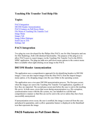
Teaching File Transfer Tool Help FileTopicsPACS IntegrationDICOM Header AnonymizationPACS Features on Pull Down MenuFile Menu of Teaching File Transfer ToolImage MenuImages TabImage Editor DialogueSend Case to TFSSettings TabPACS IntegrationTwo plug-ins were developed for the Philips iSite PACS, one for iSite Enterprise and onefor iSite Radiology, both with identical functionality. The purpose of the plug-in is toallow PACS users to export images via the Teaching File Transfer Tool to the RSNAMIRC application. The plug-ins adds new pull down menu options to the context menuthat is available when right-clicking on an image in the PACS.DICOM Header AnonymizationThe application uses a comprehensive approach for de-identifying headers in DICOMimages. Users can also import images from the iSite PACS, from the Import Imagesmenu option, or by dropping images into the case folder in the operating system.The application uses a two-pass DICOM anonymization process. The first pass occurswhen the images are sent to the Teaching File Transfer Tool application, regardless ofhow they are imported. The second pass occurs just before the case is sent to the teachingfile server. In both cases, errors that occur during anonymization (e.g. file corruption,synchronization issues with the file system, etc.) are handled in a careful andcomprehensive manner so that files are not be sent to the server unless they have beensuccessfully anonymized.If anonymization errors occur, the user is notified, the image is removed from the caseand placed in quarantine, and a yellow quarantine banner is displayed on the thumbnailicon that represents the image.PACS Features on Pull Down Menu
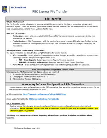
Right-clicking while the cursor is over an active PACS image will allow the user to seethe full right-click menu. The header Teaching File is at the bottom of this menu list.The following operations are supported:· Create a new teaching file case. When this option is selected, the Transfer Toolapplication is started, if it is not already running, and a new folder is created for thecase.· Open an existing case. The application is started if it is not already running. Thisoption allows the user to select the folder for an existing case by navigating the filesystem on the machine to the directory path for the previously saved case.The following three commands require the Teaching File Transfer Tool to be alreadyopen and an active case in progress:· Export DICOM image. The selected DICOM image is written to the folder for thecurrent teaching file case. The image file is then automatically anonymized by theapplication.· Export DICOM series. Same as previous option, except all images in the selectedimage series are written to the current teaching file directory.· Export RIS report. The RIS report is exported to the current teaching file directory.This feature is not currently supported, but may be activated if patient confidentialityissues can be resolved.
File menu of Teaching File Transfer Tool
New case. Create a new teaching file case. Auto-create automatically generates a newdirectory for the case in the default teaching file directory. Specify directory allows theuser to specify the location and directory name that will be used for the new case.Open case. Open an existing case. Open case file allows users to open a case by selectinga valid case file with either an .xml or .zip extension. Open directory allows the user toopen an existing case by specifying its directory. Most often one should search for oldcase by opening the old directory.Close case. Close the current case.Save locally. Save the case on the local computer.Send to TFS. This option packages the teaching file case and sends it to the TFS server.Several steps are used to package and transfer the case:1. Save the case locally.2. Anonymize the headers in all DICOM files.3. Generate thumbnails and full size JPG versions of all DICOM images.4. Create a ZIP file that contains all case content5. Authenticate credentials and send case to the server6. Ask the user if the case should be deleted on the local computer.Exit. Exit the application.Image MenuAnonymize files. Anonymize any DICOM image files in the file system. The files areanonymized and resaved in their current directory, and the images are not opened orcopied into the current case. They are not added to an open case at the time youanonymize them. After these images are anonymized they can be used in otherapplications or imported into the Teaching File Transfer Tool.Import images. Add the selected images to the teaching file case. The selected images arecopied into the current case directory and are anonymized. The application supportDICOM, JPG, GIF, PNG, TIF, JPEG2000, and BMP images.Screen capture. Capture images from the screen and saves them as PNG images. Whenthis option is selected, a semi-transparent capture panel appears on the screen. The panelcan be resized by clicking and dragging its edges and corners, and it can be moved byclicking and dragging in any other location. The panel contains two buttons: a Capturebutton, and a Cancel button. When the Capture button is pressed, the region located underthe panel is captured and save as a PNG image, which is then automatically imported intothe application. When the Cancel button is pressed, the panel is dismissed.
Images TabThe images tab displays thumbnail versions of all images that have been imported intothe teaching file case, and it allows the user to edit the image to remove patientinformation from the pixels. The application is able to handle several types of images,including GIF, JPG, PNG, BMP, TIF, JPEG2000, and DICOM (series, multiframe, andindividual images). The tab automatically arranges images and visually groups DICOMimages that are part of the same series.User interface componentsImage panels. All images that are opened in the application are displayed in imagepanels. A separate panel is added for each DICOM image series, and all JPG, GIF, BMP,TIF, JPEG2000 and PNG images are shown on the same panel. Each image panel has atext heading that shows the modality type (if DICOM), the number of images in thepanel, and the image type(s). The panel also contains an expand / collapse button.Thumbnail icon. Each image is displayed using a thumbnail icon showing a miniatureversion of the image source. All icons are displayed in image panels (see above), and theicons are interactive. They can be selected by left-clicking on them, and multiple iconscan be selected by holding down the Ctrl key while clicking. Icons have additionalinformation embedded in them:· Information box. A white box is displayed in the lower right corner of each icon. Ina DICOM series, the box shows the position of the image in the series (taken fromthe DICOM header). For multiframe images, the box shows “MF”, for other types ofimages, it shows the abbreviated file type (i.e. “JPG”, “PNG”, “GIF”).· Quarantine banner. When an error occurs while anonymizing a DICOM image, it isplaced in quarantine and a yellow quarantine banner is displayed across thethumbnail icon.· Check image banner. The application maintains a list of image stations that canpotentially embed patient information in the image pixels. If a DICOM imageoriginated at one of these stations, the application displays a semi-transparent redbanner, containing the text “Check img”, across its icon to warn the user that theyshould inspect the image to guarantee that it is de-identified.Buttons and controlsExpand / collapse button. Each image panel contains an expand / collapse button in theupper left corner. When the button is in collapse mode (a “–” is shown on the button),pushing it will cause the panel’s thumbnail icons to be hidden. When it is in expand mode(a “ ” is shown on the button), pushing it shows the panel’s thumbnail icons.Popup menu
View, blackout, crop. Launches the image editor dialog.External viewer. Launches the current image in an external viewer. Before using thisoption, a DICOM viewer must be installed on your machine, and the DICOM MIME typemust be associated with the viewer.Collapse all. Collapses all image panels, hiding their thumbnail icons.Expand all. Expands all image panels, showing their thumbnail icons.Delete. Deletes the selected image(s), removing their thumbnails and deleting the files.DICOM header. If a DICOM image is selected, a dialog is displayed that shows itsheader tags and their associated values.Create video. Not currently active.Merge series to multiframe. When a DICOM image series, consisting of more than oneDICOM file, is selected, this option merges the series, generating a single multiframeimage and deleting the original images.Anonymize. Anonymizes the DICOM header of a selected DICOM image(s).Quarantine. Move the selected image(s) into quarantine.Remove from quarantine. Remove the selected image(s) from quarantine.Note: Ultrasound images will always have imbedded patient identification. It isimperative that you redact this information by using the Image editor! See below!Image Editor Dialogue
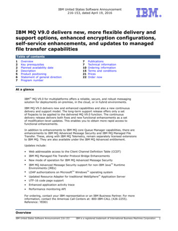
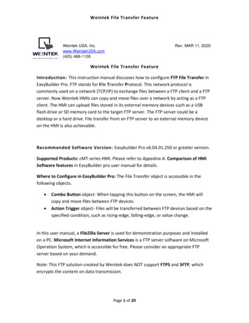
The figure above is labelled with numbers. The numbers correspond to informationprovided below and highlighted in the brackets.The image editor is triggered through the images tab in one of two ways: 1) by doubleclicking on an image, or 2) by selecting an image, right clicking, and selecting Editimage(s) from the popup menu. The image editor dialog allows users to view the originalimage associated with an image icon. By default, images are displayed at their originalsize, but the user can zoom the image in the display, changing its magnification level.The user-interface is divided into four main parts: a thumbnail region, a toolbar, an imageviewing region, and a settings bar.The thumbnail region (left side of the figure) shows miniature versions of each image inthe set. Images are loaded and displayed in the image viewing region when: theirthumbnail is clicked, the next image button (5) is clicked, or the previous image button(1) is clicked. A blue border is shown around the thumbnail for the image that is currentlydisplayed in the image viewing region (31).All operations can be applied either to every image in the series or to a subset of theimages. By default, all images in the series are selected for editing. Two buttonsdisplayed at the top of the thumbnail region allow images to chosen, and this designationis shown by placing a red border around the thumbnails for the images (30). The edit allbutton (3), shown using a table with all cells selected, highlights all icons in a set andapplies all operations to them. The edit subset button (4), shown using a table with acolumn selected, highlights all icons that are currently selected (i.e. if thumbnails have ablue border around them when the button is pressed, their border will turn red, showingthat they are now being edited).Many images have an associated annotation file containing arrows and text that point toimportant locations and structures. Creating separate annotation images allows you to addimportant explanatory details without modifying the original image. When annotationfiles are available in, the annotation button is visible (2). Pressing the annotation buttonwill toggle between the original image and the annotation image. When annotations aredisplayed, the thumbnail for the image will show the annotation and a small banner,labeled "Annotation", will be shown at the top of the thumbnail (30). When images withannotations are uploaded to the teaching file server, the user will be able to switchbetween the original image and the annotation.The viewer allows you to change the image display using zoom and pan controls. Themagnification can be changed by using the zoom slider (32), and the image can bepanned using either the overview control (29) or the pan button (16). The overviewcontrol is shown when the image is larger than the display area. It contains two bluerectangles—the large rectangle represents the image dimensions, and the small nestedrectangle represents the region of the image that is currently being displayed. The imagecan be panned by clicking on the small nested rectangle and dragging it to a different part
of the large rectangle. The pan button allows you to pan the image by clicking on themain image and dragging it to the desired position.All operations are undo-able and redo-able (22,23), and modifications are not applied tothe image until the save option is selected (45). Once changes are saved, there is no wayto undo the modifications.The main toolbar is shown at the top of the display. The top row contains these buttons: Rectangle button (6). Draw a rectangle. Circle button (7). Draw a circle. Triangle button (8). Draw a triangle. Polygon button (9). Draw a polygon. Filled arrow button (10). Draw a wide arrow. Line arrow button (11). Draw a line arrow. Line button (12). Draw a line. Freehand button (13). Draw a freehand line. Text button (14). Create a text label. Select button (15). Select shapes and text labels. Individual items can be selectedby clicking on them. Multiple items can be selected by holding down the Ctrlbutton and clicking on them. Selected items can be deleted by pressing the Deletebutton on your keyboard, and can be moved by dragging them to a new location. Pan button (16). Pan the image by clicking and dragging to a new location. Image processing button (17). Display the image processing menu. All options inthis menu should be used with care since image-processing operations require asignificant amount of memory, and may cause memory errors when they areapplied to large images (file size approximately 5MB or greater). Availableoptions are: smooth, sharpen, invert image, median filter, Sobel edge detection,Prewitt edge detection, Frei and Chen edge detection, Robert's cross edgedetection, rotate, flip horizontal, and flip vertical. Fill shape (18). Fill a shape using the current fill color (set in 35). Change line color (19). Change the line color used in shapes and text to thecurrent line color (set in 36). Blackout button (21). Blackout is a pixel anonymization operation that turns allpixels in the selection region to black. Blackout is automatically applied to allimages in series and multiframe images. Crop button (20). Crop is a pixel anonymization operation that changes the size ofthe image, deleting all pixels that fall outside of the selection rectangle. Crop isautomatically applied to all images in series and multiframe images.o Creation of a selection rectangle. Left click to set the start point, drag andrelease the button to set the end point.o Deleting a selection rectangle. Right clicking deletes the current selectionrectangle. Resizing a selection rectangle.o Resizing the selection rectangle. Move the cursor to the edge of therectangle, left click and drag the edge, and release the button to completethe operation.
ooMoving a selection rectangle. Click in the center of the selection rectangleand drag it to the desired position.Apply the crop operation. Click on the crop button a second time once theselection rectangle is properly positioned.The second row contains these buttons: Undo button (22). Undo the last operation. Redo button (23). Redo an operation. Save button (24). Save the changes made in the editor. The save dialog may giveyou several options on how you want to apply your changes (options depend onthe type of image(s) you are working with). All pixel-anonymization operations(crop and blackout) are applied directly to the DICOM images and to all imagesin the series. Please note: saved changes are not undoable.o Create a new annotation file. Save modifications as a separate annotationfile--do not change the DICOM source. If an annotation file already exists,overwrite it.o Merge changes with existing annotation file. When an annotation file isalready present, this option merges new changes with the exiting file.o Apply all changes to DICOM source. Save changes by modifying theoriginal DICOM file. The file will be converted to RGB, allowing colorshapes and text to be stored. Cancel button (25). Close the editor dialog.Font dropdown (26). Specify the font that will be used in text labels.Style dropdown (27). Specify the style that will be used in text labels--optionsinclude plain, bold, italic, and bold-italic.Size dropdown (28). Specify the font size that will be used in text labels.The settings bar is shown at the bottom of the display. The controls are listed below alongwith the functions that they support: Zoom slider (32). Change the magnification level used to display the image.Brightness slider (33). Change the brightness of the image.Contrast slider (34). Change the image’s contrast settings.Fill color dropdown (35). Set the fill color used in new shapes.Line color dropdown (36). Set the color used when draw new shapes and textlabels.Line width dropdown (37). Set the width of the line used when drawing newshapes.Static caption field (38). Captions can be added to images, and they will bedisplayed below the image in the teaching file server. Static captions are alwaysvisible when the image is displayed.Clickable caption field (39). Clickable captions are only visible if the user clickson a hyperlink that is displayed beneath the image by the teaching file server. Thisis potentially valuable when cases are built to support anonymous browsing,
where users view cases and try to determine the diagnosis without relying oninformation from the case author.Editing a Case with Ultrasound ImagesUltrasound images have patient information embedded in them that is not extractable byDicom anonymization.Therefore, the ultrasound images must be edited with the Image Editor to remove thisinformation that is displayed with each individual image.To do this, execute the following steps:
1) Open the ultrasound images in the Image Editor.2) Select the first image to view in the list of thumbnails.3) You can use the ‘Crop Tool’ or the ‘Blackout Tool’ to eliminate the patientinformation from this image.
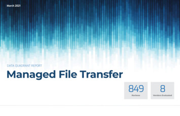
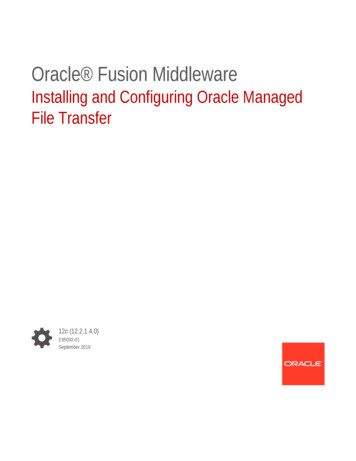
4) The image below demonstrates the region of the image blacked out with the BlackoutTool.5) You must now apply this blackout to all images in the series as depicted in the imageabove. This will then apply this blackout box to each individual image in the series,clearing them of unique patient identifiers.6) Click the save button and the modified images will be sent back to the Teaching FileTransfer Tool.
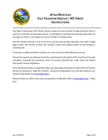
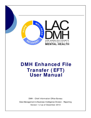
7) A pop-up box will appear and you should select Apply all changes to the dicomsource.
8) The editing of the ultrasound images is complete and you can close the Image Editor.9) If you are done adding images then you can send the case to MIRC via the TeachingFile Authoring Tool. Alternatively, you can add more images as you see fit.Send Case to TFSWhen you have compiled and edited all the images you require for your case it is time tosend the case to our local MIRC server using the ‘Send to TFS’ command from the FileMenu.The following login box will appear when you execute this order.
You need a MIRC server User Name and Password to have been assigned by theAdministrator.The server settings in the login box must be:http://mistr.usask.ca:1085This controls where the images will be sent and how they will be found when you loginto the MIRC server.Settings TabThe settings tab contains some options that can be used to configure the behavior of theapplication. When the settings shown in the tab are changed, the new values areautomatically saved.
that is available when right-clicking on an image in the PACS. DICOM Header Anonymization The application uses a comprehensive approach for de-identifying headers in DICOM images. Users can also import images from the iSite PACS, from the Import Images menu option, or by dropping images into the case folder in the operating system.