Transcription
Outdoor Tankless Water HeaterInstallation and Operation ManualFull-length French and Spanish versionsavailable online at rinnai.usFOR OUTDOOR APPLICATIONS ONLYV53De . REU-AM1620WD-USThis entire manual must be left for the consumer.The consumer must read and refer to this manual forproper operation and to maintain the water heater.PlaceModel/Serial #Label HereLocated in Manual BagLow Lead ContentNSF/ANSI 372ANSI Z21.10.3 CSA 4.3READ ALL OF THE INSTRUCTIONS THOROUGHLY BEFORE INSTALLING OR OPERATING THIS WATER HEATER.This manual provides information on the installation, operation, and maintenance of the water heater. For properoperation and safety, it is important to follow the instructions and adhere to the safety precautions.A licensed professional must install the water heater according to the exact instructions on pages 4-20.The consumer must read the entire manual to properly operate the water heater and to have regular maintenanceperformed.WARNINGIf the information in these instructions is not followed exactly, a fire or explosion may resultcausing property damage, personal injury or death.— Do not store or use gasoline or other flammable vapors and liquids in the vicinity of this or any other appliance.— WHAT TO DO IF YOU SMELL GAS: Do not try to light any appliance. Do not touch any electrical switch; do not use any phone in your building. Immediately call your gas supplier from a neighbor’s phone. Follow the gas supplier’s instructions. If you cannot reach your gas supplier, call the fire department.— Installation and service must be performed by a licensed professional.WARNINGAssurez-vous de bien suivre les instructions données dans cette notice pour réduire auminimum le risque d’incendie ou d’explosion ou pour éviter tout dommage matériel, touteblessure ou la mort.— Ne pas entreposer ni utiliser d’essence ou ni d’autres vapeurs ou liquides inflammables à proximité decet appareil ou de tout autre appareil.— QUE FAIRE SI VOUS SENTEZ UNE ODEUR DE GAZ : Ne pas tenter d’allumer d’appareil. Ne touchez à aucun interrupteur ; ne pas vous servir des téléphones se trouvant dans le bâtiment. Appelez immédiatement votre fournisseur de gaz depuis un voisin. Suivez les instructions du fournisseur. Si vous ne pouvez rejoindre le fournisseur, appelez le service des incendies.— L’installation et l’entretien doivent être assurés par un installateur ou un service d’entretien qualifié oupar le fournisseur de gaz.
Table of ContentsTable of Contents . 2Safety Behaviors and Practices for theConsumer and Installer . 3Installation Instructions(for the licensed professional) . 4Prepare for Installation . 5Determine Installation Location . 5Water Quality . 5Checklist to Determine Installation Location . 8Freeze Protection . 8Mount to Wall . 8Remove the Front Panel . 9Installation of Plumbing. 9Checklist for Plumbing . 11Installation of Gas Supply . 11Connect Electricity . 13Adjust for High Altitude . 13Checklist for Gas and Electricity . 13Installation of Temperature Controller . 14Mounting the Controller . 15Final Checklist . 16Technical Data . 17Specifications . 17Dimensions. 18Pressure Drop and Water Flow Curves . 19Ladder Diagram . 20Operation Instructions . 21Consumer Operation Guidelines for theSafe Operation of your Water Heater . 22How to Use the Temperature Controller . 23How to Set the Temperature . 24Diagnostic Codes . 27Required Maintenance. 29Freeze Protection and Winterizing . 30Flushing the Heat Exchanger . 31Manual Draining of the Water Heater . 32Consumer Warranty . 33NOTICE: Rinnai sometimes shares customer contact information with businesses that we believe provideproducts or services that may be useful to you. By providing this information, you agree that we canshare your contact information for this purpose. If you prefer not to have your information shared withthese businesses, please contact customer service and ask not to have your information shared. Wewill however, continue to contact you with information relevant to the product(s) you registered and/or you account with us.If you have any questions or feel that the manual is incomplete contact Rinnai at 1-800-621-9419.Important Safety InformationSafety DefinitionsThis is the safety alert symbol. This symbol alerts you to potential hazards that can kill or hurt youand others.2DANGERIndicates an imminently hazardous situation which, if not avoided, will result in death orserious injury.WARNINGIndicates a potentially hazardous situation which, if not avoided, could result in death orserious injury.CAUTIONIndicates a potentially hazardous situation which, if not avoided, could result in minor ormoderate injury. It may also be used to alert against unsafe practices.V53De Manual
Safety Behaviors and Practices for the Consumer and InstallerWARNING / AVERTISSEMENT Before operating, smell all around the appliancearea for gas. Be sure to smell next to the floorbecause some gas is heavier than air and will settleon the floor. Keep the area around the appliance clear and freefrom combustible materials, gasoline, and otherflammable vapors and liquids. Combustible construction refers to adjacent wallsand ceiling and should not be confused withcombustible or flammable products and materials.Combustible and/or flammable products andmaterials should never be stored in the vicinity ofthis or any gas appliance. Always check the water temperature beforeentering a shower or bath. To protect yourself from harm, before performingmaintenance: Turn off the electrical power supply byunplugging the power cord or by turning off theelectricity at the circuit breaker. (Thetemperature controller does not control theelectrical power). Turn off the gas at the manual gas valve, usuallylocated immediately below the water heater. Turn off the incoming water supply. This can bedone at the isolation valve immediately belowthe water heater or by turning off the watersupply to the building. Use only your hand to push in or turn the gascontrol knob. Never use tools. If the knob will notpush in or turn by hand, do not try to repair it; call alicensed professional. Force or attempted repairmay result in a fire or explosion. Do not use this appliance if any part has been underwater. Immediately call a licensed professional toinspect the appliance and to replace any part of thecontrol system and any gas control which has beenunder water.(N’utilisez pas cet appareil s’il a été plongé dansl’eau, même partiellement. Faites inspecterl’appareil par un technicien qualifié et remplaceztoute partie du système de contrôle et toutecommande qui ont été plongés dans l’eau). Do not use substitute materials. Use only partscertified with the appliance. Should overheating occur or the gas supply fail toshut off, turn off the manual gas control valve to theappliance.(En cas de surchauffe ou si l’alimentation en gaz nes’arrête pas, fermez manuellement le robinet d’arrêtde l’admission de gaz). Do not adjust the Dip switch unless specificallyinstructed to do so. Do not use an extension cord or an adapter plugwith this appliance. Any alteration to the appliance or its controls can bedangerous and will void the warranty.CAUTION BURN HAZARD. Hot exhaust and exhaust outletmay cause serious burns. Keep away from waterheater unit. Keep small children and animals awayfrom unit. Hot water outlet pipes leaving the unit can be hotto touch. In residential applications, insulationmust be used for hot water pipes 36” or less(height) from the floors due to burn risk to children.WARNING / AVERTISSEMENTCalifornia law requires the following Proposition 65 warning to be provided:This product can expose you to chemicals including lead, lead compounds and carbon bisulfide which are knownto the State of California to cause cancer, birth defects or other reproductive harm. For more information, visitwww.P65Warnings.ca.gov.V53De Manual3
Installation InstructionsInstaller Qualifications Do not obstruct the flow of combustion andA licensed professional must install the appliance,inspect it, and leak test it before use. The warrantywill be voided due to improper installation.The installer should have skills such as: gas sizing connecting gas lines, water lines, valves,electricity, knowledge of applicable national, state, andlocal codes.If you lack these skills contact a licensed professional.Type of installation For installation in residential applications. Certified for installation in manufactured (mobile)homes.Installation StepsPrepare for Installation . 5Determine Installation Location. 5Checklist to Determine Installation Location . 8Mount to Wall . 8Remove the Front Panel . 9Installation of Plumbing . 9Checklist for Plumbing . 11Installation of Gas Supply. 11Connect Electricity . 13Adjust for High Altitude . 13Checklist for Gas and Electricity . 13Installation of Temperature Controller . 14Mounting the Controller . 15Final Checklist. 16General Instructions Do not use this appliance in an application such asa pool or spa heater that uses chemically treatedwater . (This appliance is suitable for filling large orwhirlpool spa tubs with potable water.) Do not use substitute parts that are not authorizedfor this appliance.MUST DO The installation must conform with local codes or,in the absence of local codes, with the NationalFuel Gas Code, ANSI Z223.1/NFPA 54, or theNatural Gas and Propane Installation Code, CSAB149.1. If installed in a manufactured home, theinstallation must conform with the ManufacturedHome Construction and Safety Standard, Title 24CFR, Part 3280 and/or CAN/SCA Z240 MH Series,Mobile Homes. The appliance, when installed, must be electricallygrounded in accordance with local codes or, in theabsence of local codes, with the National ElectricalCode, ANSI/NFPA 70, or the Canadian ElectricalCode, CSA C22.1. The appliance and its appliance main gas valvemust be disconnected from the gas supply pipingsystem during any pressure testing of that systemat test pressures in excess of 1/2 psi (3.5 kPa)(13.84 in W.C.). The appliance must be isolated from the gas supplypiping system by closing its individual manualshutoff valve during any pressure testing of the gassupply piping system at test pressures equal to orless than 1/2 psi (3.5 kPa) (13.84 in W.C.). You must follow the installation instructions andDO NOTthose in Care and Maintenance for adequatecombustion air intake and exhaust. Do not install the V53De indoors. Do not install the appliance in an area where waterleakage of the unit or connections will result indamage to the area adjacent to the appliance or tolower floors of the structure. When such locationscannot be avoided, it is recommended that asuitable drain pan, adequately drained, be installedunder the appliance. The pan must not restrictcombustion air flow.4ventilation air. Combustion air shall not besupplied from occupied spaces.INFORMATION If a water heater is installed in a closed watersupply system, such as one having a backflowpreventer in the cold water supply line, meansshall be provided to control thermal expansion.Contact the water supplier or local plumbinginspector on how to control thermal expansion.V53De Manual
Should overheating occur or the gas supply fail toshut off, turn off the manual gas control valve tothe appliance. Keep the air intake location free of chemicals suchas chlorine or bleach that produce fumes. Thesefumes can damage components and reduce thelife of your appliance.Prepare for installationParts included Tankless water heaterTools needed Pipe wrenches (2) Adjustable pliers Screwdrivers (2) Wire cutters Gloves Safety glasses LevelTools that might be needed Hammer drill with Core drill with diamondconcrete bitshead Saw Torch set Threading machine with Copper tubing cutterheads and oiler Steel pipe cutter Teflon tape(recommended) or pipecompoundMaterials that may be needed Heat tape Pipe insulation Electrical wire andconduit per local code Concrete wall anchors Optional pipe cover Optional temperaturecontrollerWater QualityConsideration of care for your water heater shouldinclude evaluation of water quality.The water must be potable, free of corrosivechemicals, sand, dirt, or other contaminates. It is upto the installer to ensure the water does not containcorrosive chemicals, or elements that can affect ordamage the heat exchanger. Water that containschemicals exceeding the levels below affect anddamage the heat exchanger. Replacement of theheat exchanger due to water quality damage is notcovered by the warranty.Maximum LevelTotal HardnessUp to 200 mg / LAluminum *Up to 0.2 mg / LChlorides *Up to 250 mg / LCopper *Up to 1.0 mg / LDissolved Carbon Dioxide (CO2) 5/8” ID PVC flexible tubing2 conductor 22 AWGwire for controllerSingle gang electricalboxWire nutsUnions, drain valves,isolation valvesDetermine Installation LocationUp to 15.0 mg / L or PPMIron *Up to 0.3 mg / LManganese *Up to 0.05 mg / LpH *6.5 to 8.5TDS (Total Dissolved Solids) *Zinc *Materials needed Soap solution Pressure relief valvecondensate disposal can be found in their respectiveinstallation sections of this manual.Up to 500 mg / LUp to 5 mg / L* Source: Part 143 National Secondary Drinking WaterRegulationsIf you install this water heater in an area that isknown to have hard water or that causes scale buildup the water must be treated and/or the heatexchanger flushed regularly.When scale build-up in the heat exchanger begins toaffect the performance of the water heater, adiagnostic code “LC#” will display. Flush the heatexchanger to prevent damage to it. Scale build up iscaused by hard water set at a high temperature.Rinnai offers Southeastern Filtration’s “ScaleCutterWater Conditioning System” that offers superior limescale prevention and corrosion control by feeding ablend of control compounds into the cold watersupply.Part NumberYou must ensure that clearances will be met.103000038Consider the installation environment, water quality,and need for freeze protection. Requirements for the103000039gas line, water lines, electrical connection, andV53De ManualDescriptionSoutheastern FiltratrionScaleCutter System 3/4” FeedScaleCutter Refill5
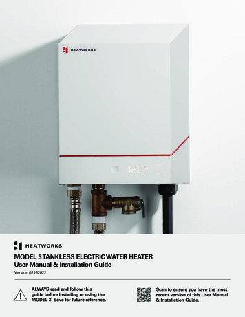
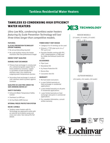
Exhaust Outlet ClearancesLRefADescriptionClearance above grade, veranda, porch, deck, or balconyCanadian Installations(CSA B149.1)US Installations(ANSI Z223.1 / NFPA 54)12 inches (30 cm)12 inches (30 cm)6 in (15 cm) for appliances 10,000 Btuh (3kW), 12 in (30 cm) for appliances 10,0004 ft (1.2 m) below or to side of opening;Btuh (3 kW) and 100,000 Btuh (30 kW), 36 in1 ft (300 mm) above opening(91 cm) for appliances 100,000 Btuh (30 kW)BClearance to window or door that may be openedCClearance to permanently closed window**DVertical clearance to ventilated soffit, located above the terminal within ahorizontal distance of 2 feet (61 cm) from the center line of the terminal**EClearance to unventilated soffit**FClearance to outside corner**GClearance to inside corner**HClearance to each side of center line extended above meter/regulatorassembly**IClearance to service regulator vent outletAbove a regulator within 3 ft (91 cm)horizontally of the vertical center line of theregulator vent outlet to a maximum verticaldistance of 15 ft (4.5 m)*J6 in (15 cm) for appliances 10,000 Btuh (3Clearance to non-mechanical air supply inlet to building or the combustionkW), 12 in (30 cm) for appliances 10,0004 ft (1.2 m) below or to side of opening;Btuh (3 kW) and 100,000 Btuh (30 kW), 36 inair inlet to any other appliance1 ft (300 mm) above opening(91 cm) for appliances 100,000 Btuh (30 kW)KClearance to a mechanical air supply inletLClearance above paved sidewalk or paved driveway located on publicpropertyMClearance under veranda, porch, deck, or balcony[1] A vent shall not terminate directly above a sidewalk or paved driveway that islocated between two single family dwellings and serves both dwellings.[2] Permitted only if veranda, porch, deck, or balcony is fully open on a minimum oftwo sides beneath the floor.6 6 feet (1.83 m)3 feet (91 cm) above if within 10 feet (3m) horizontally7 feet (2.13 m) 7 feet (2.13 m)12 inches (30 cm) *For clearances not specified in ANSI Z223.1/NFPA 54 or CSA B149.1, one of thefollowing shall be indicated:A. a minimum clearance value determined by testing in accordance with Clause5.21, Draft hoods; orB. a reference to the following footnote: “Clearance in accordance with localinstallation codes and the requirements of the gas supplier.”V53De Manual
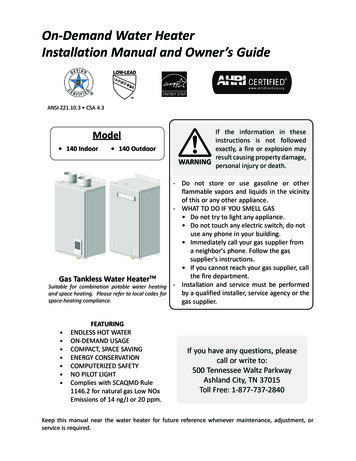
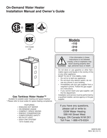
··12"36"2"60"···-
Checklist to Determine InstallationLocation The water heater is not exposed to corrosivecompounds in the air.The water heater location complies with theclearances.The planned exhaust outlet/air intake locationmeets the clearances.The water supply does not contain chemicals orexceed total hardness that will damage the heatexchanger.A 120 VAC, 60 Hz source is available.The installation must conform with local codes or,in the absence of local codes, with the NationalFuel Gas Code, ANSI Z223.1/NFPA 54, or theNatural Gas and Propane Installation Code, CSAB149.1. If installed in a manufactured home, theinstallation must conform with the ManufacturedHome Construction and Safety Standard, Title 24CFR, Part 3280 and/or CAN/SCA Z240 MH Series,Mobile Homes. Leave the entire manual taped to thetemperature controller (if installed), or give theentire manual directly to the consumer.Freeze ProtectionMake sure that in case of freezing weather that thewater heater and its water lines are protected toprevent freezing. Damage due to freezing is not covered by the warranty.In addition, the solenoid valves should be connectedelectrically to a surge protector with terminals. Thisallows the solenoid valves to operate if the waterheater is disabled due to a diagnostic code.The freeze protection features will not prevent theexternal piping from freezing. It is recommended thathot and cold water pipes are insulated. Pipe coverenclosures may be packed with insulation for addedfreeze protection.In the event of a power failure at temperatures belowfreezing the water heater should be drained of allwater to prevent freezing damage. In addition, drainthe condensate trap and drain line.Mount to Wall1. Identify the installation location and confirm thatthe installation will meet all required clearances.2. Securely attach the water heater to the wall usingany of the holes in the wall installation bracketswhich are at the top and bottom of the waterheater. Ensure that the attachment strength issufficient to support the weight. Refer to theweight of the water heater in the Specificationssection.Use a leveling tool to ensure that the waterheater is level. Proper operation requires thatthe water heater be level.NOTE: The water heater should be installed in anupright position. Do not install upside down or on itsside.Loss of freeze protection may result in water damagefrom a burst heat exchanger or water lines.With electrical power supplied, the water heater willnot freeze when the outside air temperature is ascold as –4 F (-20 C) for outdoor models, when protected from direct wind exposure. Because of the“wind-chill” effect, any wind or circulation of the airon the unit will reduce its ability to freeze protect.The unit may be drained manually. However, it ishighly recommended that: drain down solenoid valves are installed that willautomatically drain the unit if power is lost.These are available in a kit, 104000059.8V53De Manual
Remove the Front Panel Slide the plastic trim pieces on each side of thewater heater to expose the screws.INFORMATIONRemove the 4 screws and pull off the front panel.due to thermal expansion in a closed water supplysystem. Contact the water supplier or localplumbing inspector on how to correct thissituation. Do not plug the relief valve. The American National Standard (ANSI Z21.10.3)does not require a combination temperature andpressure relief valve for this appliance. However,local codes may require a combinationtemperature and pressure relief valve.Installation of PlumbingPressure Relief Valve RequirementsInstall the pressure relief valve according to localplumbing codes and these instructions.An approved pressure relief valve is required by theAmerican National Standard (ANSI Z21.10.3) for allwater heating systems, and shall be accessible forservicing.DO NOT Do not plug the relief valve and do not install anyreducing fittings or other restrictions in the reliefline. The relief line should allow for completedrainage of the valve and the line. Do not place any other type valve or shut offdevice between the relief valve and the waterheater.MUST DO The relief valve must comply with the standard for Relief Valves and Automatic Gas Shutoff Devices forHot Water Supply Systems ANSI Z21.22 and /or thestandard Temperature, Pressure, Temperature andPressure Relief Valves and Vacuum Relief Valves,CAN1-4.4.The relief valve must be rated up to 150 psi and toat least the maximum BTU/hr of the appliance.The discharge from the pressure relief valve shouldbe piped to the ground or into a drain system toprevent exposure or possible burn hazards tohumans or other plant or animal life. Follow localcodes. Water discharged from the relief valvecould cause severe burns instantly, scalds, ordeath.The pressure relief valve must be manuallyoperated once a year to check for correctoperation.The relief valve should be added to the hot wateroutlet line and near the hot water outlet accordingto the manufacturer’s instructions. DO NOT placeany other type valve or shut off device betweenthe relief valve and the water heater. If a relief valve discharges periodically, this may beIsolation ValvesRinnai strongly recommends the installation ofisolation valves on the cold and hot water linesbecause they provide the ability to isolate the waterheater from the structure’s plumbing and allow quickaccess to flush the heat exchanger. Flushing the heatexchanger regularly is required as part of the propermaintenance for this water heater.Piping RequirementsA manual water control valve must be placed in thewater inlet connection to the water heater before it isconnected to the water line. Unions may be used onboth the hot and cold water lines for future servicingand disconnection of the unit.DO NOT Do not introduce toxic chemicals such as thoseused for boiler water treatment to the potablewater used for space heating.MUST DO The piping (including soldering materials) andcomponents connected to this appliance must beapproved for use in potable water systems. Purge the water line to remove all debris and air.Debris will damage the water heater. If the appliance will be used as a potable watersource, it must not be connected to a system thatwas previously used with a non-potable waterheating appliance. Ensure that the water filter on the water heater isclean and installed.V53De Manual9
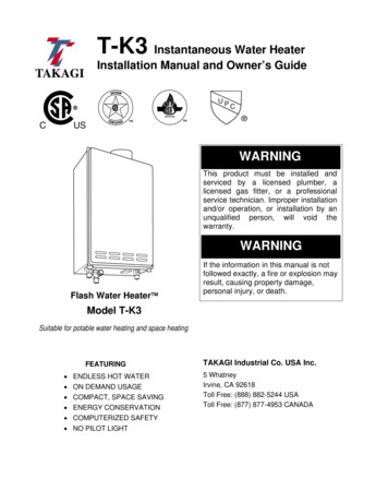
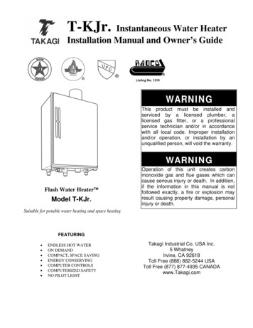
Piping Diagram for Basic InstallationRinnaiWater HeaterRinnaiEquipment ListQTYRinnaiWater Heaters1RIK-KIT (Optional)1(3/4" Fittings Include:2 Unions, 2 Ball Valves,2 Drain Valves and1 Pressure Relief Valve.)3/4" G as C on ne ctionG as Sup ply3/4" Hot Water Supply Line3/4" C old W ate r S up ply LineFor Building FixturesKEYPressure Regulator3/4" Ball ValveCirculating Pump3/4" UnionCheck ValvePressure Relief Valve10Boiler Drain ValveSSolenoid ValveThis is not an engineered drawing. It is intended only as a guide and notas a replacement for professionally engineered project drawings. Thisdrawing is not intended to describe a complete system. It is up to thecontractor/engineer to determine the necessary components andconfiguration of the particular system being installed. This drawing doesnot imply compliance with local building code requirements. It is theresponsibility of the contractor/engineer to ensure installation is inaccordance with all local building codes. Confer with local buildingofficials before installation.V53De Manual
Connect Water Heater to Water SupplyInstallation of Gas SupplyWARNING / AVERTISSEMENTWater connections to the tankless water heatershould follow all state and local plumbing codes.If this is a standard installation, refer to the PipingDiagram for Basic Installation.1. Plumb the cold water supply to the tankless waterheater on the 3/4” MNPT connection at thebottom of the unit marked “COLD.2. Plumb the building hot water supply to the 3/4”MSPT connection marked “HOT.”If a pipe cover will be installed, make sure water linesto the water heater fit.1. If you are not knowledgeable or qualified toinstall gas lines or connections, then contact alicensed professional to install the gas supply.2. Turn off 120v power supply.3. Turn off the gas.4. Gas is flammable. Do not smoke or provide otherignition sources while working with gas.5. Do not turn on the water heater or gas until allfumes are gone.General InstructionsMUST DO A manual gas control valve must be placed in thegas supply line to the water heater. A union can beused on the connection above the shut off valvefor the future servicing or disconnection of theunit.Checklist for Plumbing Purge the water line of all debris and air byclosing the hot isolation valve and opening thecold isolation valve and its drain. Debris willdamage the water heater. Use a bucket or hoseif necessary. Ensure that hot and cold water lines are notcrossed to the unit and are leak free. Check the type of gas and the gas inlet pressurebefore connecting the water heater. If the waterheater is not of the gas type that the building issupplied with, DO NOT connect the water heater.Contact the dealer for the proper unit to match thegas type. Check the gas supply pressure immediately Ensure that a pressure relief valve is installed witha rating that exceeds the BTU input of the waterheater model. Refer to the rating plate on theside of the water heater for BTU input. Clean the inlet water filter by closing the cold andhot water inlet isolation (shut-off) valves. Put abucket under the filter at the bottom of the waterheater to catch any water that is contained insidethe unit. Unscrew the water filter. Rinse thefilter to remove any debris. Install the filter andopen the isolation valves. Check for proper water pressure to the waterheater. Minimum water pressure is 20 psi. Rinnairecommends 60-80 psi for maximumperformance.upstream at a location provided by the gascompany. Supplied gas pressure must be withinthe limits shown in the Specifications section withall gas appliances operating. Before placing the appliance in operation all jointsincluding the heater must be checked for gastightness by means of leak detector solution, soapand water, or an equivalent nonflammablesolution, as applicable. (Since some leak testsolutions, including soap and water, may causecorrosion or stress cracking, the piping shall berinsed with water after testing, unless it has beendetermined that the leak test solution is noncorrosive.) Use approved connectors to connect the unit tothe gas line. Purge the gas line of any debrisbefore connection to the water heater.V53De Manual11
Any compound used on the threaded joint of thegas piping shall be a type which resists the actionof liquefied petroleum gas (propane / LPG). The gas supply line shall be gas tight, sized, and soinstalled as to provide a supply of gas sufficient tomeet the maximum demand of the heater and allother gas consuming appliances at the locationwithout loss of pressure. Refer to an approved pipe sizing chart if in doubtabout the size of the gas line.Size the gas pipeThe gas supply must be capable of handling the entiregas load at the location. Gas line sizing is based ongas type, the pressure drop in the system, the gaspressure supplied, and gas line type. For gas pipesizing in the United States, refer to the National FuelGas Code, NFPA 54. The below information isprovided as an example. The appropriate table fromthe applicable code must be used.1. For some tables, you will need to determine thecubic feet per hour of gas required by dividing thegas input by the heating value of the gas(available from the local gas company). The gasinput needs to include all gas products at thelocation and the maximum BTU usage at full loadwhen all gas products are in use.2. Use the table for your gas type and pipe type tofind the pipe size required. The pipe size must beable to provide the required
Outdoor Tankless Water Heater Installation and Operation Manual - Lowe's . d * * * * *