Transcription
On-Demand Water HeaterInstallation Manual and Owner’s GuideANSI Z21.10.3 CSA 4.3Model 140 Indoor 140 OutdoorIf the information in theseinstructions is not followedexactly, a fire or explosion mayresult causing property damage,WARNING personal injury or death.- Do not store or use gasoline or otherflammable vapors and liquids in the vicinityof this or any other appliance.- WHAT TO DO IF YOU SMELL GAS Do not try to light any appliance. Do not touch any electric switch, do notuse any phone in your building. Immediately call your gas supplier froma neighbor's phone. Follow the gassupplier's instructions. If you cannot reach your gas supplier, callthe fire department.Gas Tankless Water HeaterTMSuitable for combination potable water heating - Installation and service must be performedby a qualified installer, service agency or theand space heating. Please refer to local codes forspace-heating compliance.gas supplier. FEATURINGENDLESS HOT WATERON-DEMAND USAGECOMPACT, SPACE SAVINGENERGY CONSERVATIONCOMPUTERIZED SAFETYNO PILOT LIGHTComplies with SCAQMD Rule1146.2 for natural gas Low NOxEmissions of 14 ng/J or 20 ppm.If you have any questions, pleasecall or write to:500 Tennessee Waltz ParkwayAshland City, TN 37015Toll Free: 1-877-737-2840Keep this manual near the water heater for future reference whenever maintenance, adjustment, orservice is required.
Installation ManualContentsCONTENTSOwner's GuideInstallation ManualSPECIFICATIONS.4INTRODUCTION.5SAFETY GUIDELINES.6SAFETY NCES.9INCLUDED ACCESSORIES.9OPTIONAL ITEMS.9WARNING FOR INSTALLATIONS.11HIGH-ALTITUDE INSTALLATIONS.12VENTING INSTRUCTIONS.13General.13Combustion air supply.14Exhaust vent (ABS,PVC,CPVC, orpolypropylene vent).18DIP switch settings for vent length(ABS,PVC,CPVC, or polypropylene vent).19Exhaust vent (Stainless steel vent).22DIP switch settings for vent length(Stainless steel vent).23Vent termination clearances.25Clearances for sidewall terminations.26Clearances for rooftop terminations.27GAS SUPPLY AND GAS PIPE SIZING.28General.28Gas connections.28Natural Gas supply piping.29Propane (LP) supply piping.29WATER CONNECTIONS.30Pressure relief valve.30CONDENSATE DRAIN.31Condensate drain connections.31ELECTRICAL CONNECTIONS.33TEMPERATURE REMOTE CONTROLLER.33Included accessories.33Installation.34APPLICATIONS.35Space heating applications.35Recirculation.35Dual-purpose hot water heating.36INITIAL OPERATION.37OPERATING SAFETY.39NORMAL OPERATION.41BUILT-IN AND REMOTE CONTROLLER.41GENERAL.41TEMPERATURE TABLE OF CONTROLLER.41OUTLET WATER TEMPERATURESETTING.42Using controller.42Temperature setting on the PCB.42ADDITIONAL FEATURES.43Information mode.43Unit conversion mode.43FLOW. 44FREEZE PROTECTION SYSTEM. 44MAINTENANCE AND SERVICE. 44Measuring inlet gas pressure.45UNIT DRAINING AND FILTER CLEANING. 45TROUBLESHOOTING.46ERROR CODES.47Fault analysis error code.48COMPONENTS DIAGRAM.50PARTS LIST.54OUTPUT TEMPERATURE CHART.56This installation manual is approved for installation in the United States.2Page
Installation ManualInstallation ManualCONGRATULATIONSCongratulations and thank you for choosing our tankless water heater.Before use, we recommend that you read through this installationmanual carefully. Keep this manual for future reference.If you need an additional manual, contact the manufacturer or yourlocal distributor. When you call, please tell us the product name andthe serial number of your unit written on the rating plate of the waterheater.3Page
Installation ManualSpecificationsSPECIFICATIONSModel140 Indoor140 OutdoorNatural Gas Input(Operating Range)BTU/hMin.: 15,000Max.: 120,000Propane Input(Operating Range)BTU/hMin.: 15,000Max.: 120,000Gas Connection1/2" NPTWater Connection3/4" NPTNatural gasInlet PressurePropaneInlet Pressurepsi(MPa)inch W.C.(kPa)inch W.C.(kPa)Weightlbs. (kg)Water Pressure*15 - 150 (0.1 - 1.0)Min. 4.0 (1.0)Max. 10.5 (2.6)Min. 8.0 (2.0)Max. 14.0 (3.5)50 (22.5)inchDimensionH 21-3/4 x W 14 x D 9-1/4H 552 x W 352 x D 236mmIgnitionElectric IgnitionVAC / Hz120 / 60OperationW/A53.9 / 0.7StandbyW/A3.2 / 0.05FreezeProtectionW/A223.9 / 1.94ConsumptionSupplyElectric50 (22.5)Water heater category**Category IVN/A*40 psi or above is recommended for maximum flow.**Water heater Category — water heaters of other than direct vent type, for outdoor installation, are divided into fourcategories based on static pressure produced in the vent and flue loss.Category I - a water heater that operates with a non-positive vent static pressure and with a vent gas temperaturethat avoids excessive condensate production in the vent.Category II - a water heater that operates with a non-positive vent static pressure and with a vent gas temperaturethat may cause excessive condensate production in the vent.Category III - a water heater that operates with a positive vent static pressure and with a vent gas temperature thatavoids excessive condensate production in the vent.Category IV - a water heater that operates with a positive vent static pressure and with a vent gas temperature thatmay cause excessive condensate production in the vent.NOTE: Check the rating plate to ensure that this product matches your specifications. The manufacturer reserves the right to discontinue, or change at any time, specifications or designswithout notice and without incurring obligation.4Page
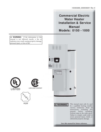
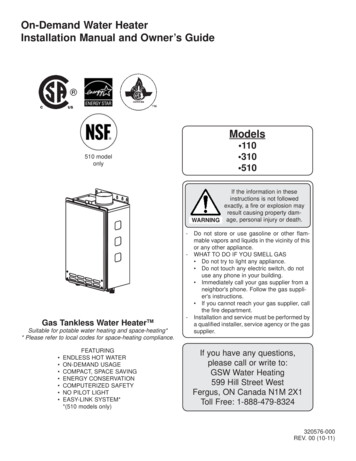
Installation ManualIntroductionINTRODUCTION This manual provides information necessary for the installation, operation, and maintenanceof the water heater. The model description is listed on the rating plate which is attached to the side/front panel ofthe water heater. Please read all installation instructions completely before installing this product. If you have any problems or questions regarding this equipment, consult the manufacturer orits local representative. This equipment is an on-demand, tankless water heater designed to efficiently supply endlesshot water for your needs. These high efficiency models have a built-in secondary heat exchanger that absorbs latentheat from the exhaust gas. The 140 Indoor model is only to be installed indoors. The 140 Outdoor model is only to beinstalled outdoors. The principle behind tankless water heaters is simple:ExhaustSecondaryheat exchangerIntake portExhaustThermistorPrimaryheat exchangerBurnersWater controlvalveGas valveComputerboardFan motorFlow sensorThermistorHot water outletIgniterCondensatedrain portGas inletCold water inletThermistor*This diagram illustrates tankless water heater design concepts only and does not accuratelyrepresent the water heater’s physical description.1.2.3.4.5.6.7.8.A hot water fixture is turned on.Water flows through the heater.The water flow sensor detects the water flow.The computer initiates the fan motor and gas valve to let gas flow through the heater and sends asignal to the igniter to create an ignition spark.The gas ignites and flames appear within the burner chamber.Water is heated as it flows through the heat exchanger.Using thermistors to measure temperatures throughout the water heater, the computer modulatesthe gas and water valves to ensure proper output water temperature and hot water outflows.When the fixture is turned off, the unit shuts down.5Page
Installation ManualSafety GuidelinesSAFETY GUIDELINESSAFETY DEFINITIONDANGERWARNINGCAUTIONNOTICEIndicates an imminently hazardous situation which, if not avoided, will result indeath or serious injury.Indicates an imminently hazardous situation which, if not avoided, could resultin death or serious injury.Indicates an imminently hazardous situation which, if not avoided, could resultin minor or moderate injury.Indicates information considered important but not hazard related.GENERAL1. Follow all local codes, or in the absence of local codes, follow the current edition of the NationalFuel Gas Code: ANSI Z223.1/NFPA 54 in the USA or B149.1 Natural Gas, Propane Installation Code inCanada.2. Properly ground the unit in accordance with all local codes or in the absence of local codes, with theNational Electrical Codes: ANSI/NFPA 70 in the USA or CSA standard C22.1 Canadian Electrical CodePart 1 in Canada.3. Carefully plan where you intend to install the water heater. Please ensure: Your water heater will have enough combustible air and proper ventilation. Locate your heater where water leakage will not damage surrounding areas. (Please refer to p. 8.)4. Check the rating plate for the correct GAS TYPE, GAS PRESSURE, WATER PRESSURE and ELECTRICRATING.*If this unit does not match your requirements, do not install and consult with the manufacturer.5. If any problem should occur, turn off all hot water taps and turn off the gas. Then call a trainedtechnician, the gas company, or the manufacturer.WARNING Water temperatures over 125 F (52 C) can cause severe burns instantly or death fromscalding. The water temperature is set at 120 F (50 C) from the factory to minimize anyscalding risk. Before bathing or showering always check the water temperature. Do not store or use gasoline or other flammables, vapors, or liquids in the vicinity of thisappliance. Do not reverse the water and/or gas connections as this will damage the gas valves andcan cause severe injury or death. Follow the diagram on p. 30 when installing your waterheater. Should overheating occur or the gas supply fails to shut off, turn off the manual gas controlvalve to the appliance. Do not use this appliance if any part has been in contact with or been immersed in water.Immediately call a qualified installer or service agency to replace a flooded water heater.Do not attempt to repair the unit. It must be replaced. Do not disconnect the electrical supply if the ambient temperature will drop belowfreezing. The Freeze Protection System only works if the unit has electrical power. Thewarranty will not be covered if the heat exchanger is damaged due to freezing. Refer tothe section on the Freeze Protection System on p. 44 for more information. Failure to observe these warnings could result in severe personal injury or death.6Page
Installation ManualInstallationINSTALLATIONGENERAL1. Follow all local codes, or in the absence of local codes, follow the current edition of the NationalFuel Gas Code: ANSI Z223.1/NFPA 54 in the USA or B149.1 Natural Gas, Propane Installation Code inCanada.2. All gas water heaters require careful and correct installation to ensure safe and efficient operation.This manual must be followed exactly. Read the “Safety Guidelines” section.3. The manifold gas pressure is preset at the factory. It is computer controlled and should not needadjustment.4. Maintain proper space for servicing. Install the water heater so that it can be connected or removedeasily. Refer to the "Clearances" section on p. 9 for proper clearances.5. The water heater must be installed in a location where the proper amount of combustible air will beavailable to it at all times without obstructions, or the indoor heater may be direct vented.6. Electrical service to the water heater requires a means of disconnection. This will allow power to thewater heater to be shut off for servicing and safety purposes.7. Do not install the unit where the exhaust vent is pointing into any opening in a building or where thenoise may disturb your neighbors. Make sure the vent termination meets the required clearance fromany doorway or opening to prevent exhaust from entering a building. (Refer to pp. 11, 25 and 26.)Check local code requirements prior to installation.8. Carefully plan the installation location of the heater and vent terminations. Contaminants such asaerosols, lint, and fine powders (including flour) can clog the air intake and reduce the operation of thefan. This, in turn, can cause improper combustion and reduce the life of the water heater. Regularlyensure that the area around the water heater, vent termination, and air intake is free of dust, debris,and other contaminants. In environments with a high level of contaminants (laundry facilities, hairsalons, pet salons, chemical plants, commercial kitchens, etc.), direct venting is required.9. The 140 Indoor model is to be installed indoors only. The model is equipped with a thermistor andhi-limit switch for the exhaust gas, detecting excess temperatures within the flue and enabling thewater heater to safely stop operation if needed. These components are always monitoring exhaust gasconditions in order to prevent heat damage to ABS, PVC (solid core), CPVC (solid core), or Polypropylene(Plastic) venting if ABS, PVC, CPVC, or Polypropylene is used. If the exhaust gas temperature exceeds140 F (60 C) these components will enable the water heater to safely stop operation. (Thesecomponents are not installed on the outdoor model since the exhaust vent is built-in.) If the water heater is used as a direct-vent appliance, the unit requires 3 in (76 mm) or 4 in (102mm) combustion air supply pipe. The intake pipe must be sealed airtight. Refer to pp. 13 to 27for more detail. Air supply pipe can be made of aluminum flexible tube, ABS, PVC (solid core), CPVC (solid core),Polypropylene, corrugated stainless steel, or Category lll / IV stainless steel. Regarding exhaustpipe, please refer to pp.18 to 24 for detailed information. Use of cellular core PVC (ASTM F891), cellular core CPVC, or Radel (polyphenylsulfone) in nonmetallic venting systems is prohibited. Covering non-metallic vent pipe and fittings with thermalinsulation is prohibited. Terminating the venting through a sidewall is recommended for the direct-vent system.Terminating in the same pressure zone allows for pressure balancing, which prevents nuisanceshutdowns. Only install the water heater in a heated area where below freezing temperatures cannot occur. Thewarranty does not cover damage caused by freezing. The manufacturer recommends running the exhaust vent and the intake pipe as parallel as possible. The water heater must be securely mounted to a wall or other suitable structure.10. The 140 Outdoor model must only be installed outdoors and only in the area with mild, temperateclimates. The Outdoor model shall be wall-mounted or mounted on a stand. Locate the Outdoormodel in an open, unroofed area and maintain the minimum clearances. (Refer to pp.9 and 11.)7Page
Installation ManualInstallation Installation and service must be performed by a qualified installer (for example, alicensed plumber or gas fitter). Otherwise, the warranty will be void. The installer (licensed professional) is responsible for the correct installation of thewater heater and for compliance with all national, state/provincial, and local codes.WARNING The manufacturer does not recommend installing the water heater in a pit orlocation where gas and water can accumulate. Do not have the vent terminal pointing toward any operating window, door, oropening into a building. Do not install next to any source of airborne debris, such as a clothes dryer, thatcan cause debris to be trapped inside the combustion chamber, unless the system isdirect-vented. Do not install the unit where water, debris, or flammable vapors may get into the flueterminal or the air intake line. The manufacturer does not recommend installing the water heater in an attic dueto safety issues. If you install the water heater in an attic: Make sure the unit will have enough combustion air and proper ventilation.Failure to do so could lead to carbon monoxide poisoning or death. Keep the area around the water heater clean. When dust collects on the flamesensor, the water heater will shut down on an error code. Place the unit where it will allow easy access for service and maintenance. A drain pan, or other means of protection against water damage, isrecommended to be installed under the water heater in case of leaks. Failure to observe these warnings could result in severe personal injury, death,and/or property damage.NOTICE The warranty will not cover damage caused by water quality. Only potable water can be used with this water heater. Do not introduce poolor spa water, or any chemically treated water into the water heater. Water hardness levels must not exceed 7 grains per gallon (120 ppm) forsingle family domestic applications or more than 4 grains per gallon (70 ppm)for all other types of applications. Water hardness leads to scale formationand may affect/damage the water heater. Hard water scaling must be avoidedor controlled by proper water treatment. Water pH levels must be between 6.5 and 8.5. Well water must be treated. The manufacturer recommends direct venting when the water heater is installedin beauty salons, dry cleaners or any other locations in which such chemicalsare present in the air. Some chemicals used in beauty salons or dry cleaners mayaffect the flame sensor. In such cases, the water heater may not work properly. Although the water heater is designed to operate with minimal sound, themanufacturer does not recommend installing the unit on a wall adjacent to abedroom, or a room that is intended for quiet study or meditation, etc. Locate your heater close to a drain where water leakage will not do damage tosurrounding areas. As with any water heating appliance, the potential for leakageat some time in the life of the product does exist. The manufacturer will not beresponsible for any water damage that may occur. If you install a drain pan underthe unit, ensure that it will not restrict the combustion air flow.8Page
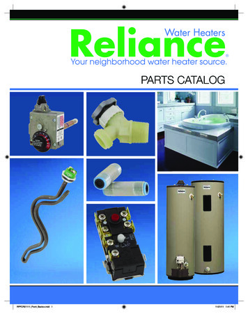
Installation ManualInstallationCLEARANCESTopMaintain all clearances around the waterheater. Failure to do so could create a firehazard, potentially leading to death, seriousWARNING injury, and/or property ackSides140 Indoor12 in.(305 mm)12 in.(305 mm)4 in.*(102 mm)1 in.(25 mm)3 in.(76 mm)140 Outdoor36 in.(914 mm)12 in.(305 mm)24 in.(610 mm)1 in.(25 mm)3 in.(76 mm)*24 inches recommended for maintenance.INCLUDED ACCESSORIESInstallation manual Temperature remote controller kit*Bird screenand owner’s guideOutdoor model onlyIndoor model only100209924(TM-RE42)Qty: 1Qty: 2Qty: 1OPTIONAL ITEMS#Model140 Indoor140 Outdoor1.Temperature Remote Controller Included with thewater heater2.Pipe Cover 3.Neutralizer Kit 4.4-inch Exhaust Sidewall Vent Terminator (Hood)and 4-inch Wall Thimble 5.3-inch Concentric PVCTermination 6.Recess Box 9Page
Installation ManualInstallation1. Temperature remote controller:100209924 (TM-RE42)-Standard modelThe temperature remote controllers havethree functions. It allows the outputtemperature from the water heater tobe adjusted. It also works as a diagnostictool and provides a concise error codewhenever there is a problem with the unit. See theTroubleshooting Section (pp.53 to 56) for informationon possible error codes.2. Pipe cover:100187904 (TH-PC04)The pipe cover protectsthe plumbing pipes tothe water heater fromunexpected adjustments.This pipe cover is fixedto the bottom of thewater heater, which hides the plumbing andimproves the visual aspects of the wholeinstallation.3. Neutralizer kit: 100112159 (TH-NT01)The neutralizer assembly neutralizes the condensate (acidic water) that forms in thesecondary heat exchanger of the water heater.It connects to the condensate drain port of the water heater with connectors includedwith the neutralizer kit. (Refer to pp. 32 and 33.)4. Sidewall vent terminator (Hood) and Wall thimble:Terminator HoodWall ThimbleCovering wall thicknessesTerminator HoodWall Thimble 4 - 7 in (102 - 178 mm)Wall Thimble 5 - 10 in (123 - 254 mm)Termination Thimble 4 - 7 in (102 - 178 mm)Termination Thimble 5 - 10 in (123 - 254 425These are used when venting out through the wall. These terminations are special stainless steelvents for gas appliances and are UL listed as Category II, III and IV. For different wall thicknesses, thereare two ranges of lengths available. (Refer to the NovaVent brochure for details.) Install these ventterminations in accordance with their installation instructions and any applicable local codes.5. 3" PVC concentric termination: 100112163 (TH-CVPVC33)Used when terminating direct-vent (sealed combustion)systems, with Indoor models that require a 3 in. (76 mm) intakeand a 3 in. (76 mm) exhaust.This concentric termination provides the convenience of only having to make one penetration through asidewall instead of two separate penetrations for the intake and exhaust piping. The termination includesa bird screen, restricting small animals, pests, and foreign objects from entering into the vent system.6. Recess box:It allows for “clean” installations. The water heater fits inside the recess box, which hides andprotects the whole water heater and plumbing. The recess box will fit between most wall studs.Outdoor recess boxfor new construction applicationswith flangeOutdoor recess boxfor retrofit applications-no flange10026672910026673010Page
Installation ManualInstallationWARNING FOR INSTALLATIONSFOR YOUR SAFETY, READ BEFORE INSTALLATION:Do not install the heater where water, debris orflammable vapors may get into the flue terminal.This may cause damage to the heater and void thewarranty.Do not have the vent terminal pointing towardany opening into a building. Do not locate yourheater in a pit or location where gas and watercan accumulate.ProhibitedProhibitedDo not install this water heater under anoverhang less than 3 ft (914 mm) from its topor eaves. The area under an overhang must beopen to three sides (Outdoor model only).Ensure that you meet the minimum clearancesshown below for a direct vent termination:USA: 1 ft (30 cm) min.Canada: 3 ft (91 cm) min.3 ft(914 mm)USA: 1 ft (30 cm) min.Canada: 3 ft (91 cm) min.USA: 1 ft (30 cm) min.Canada: 3 ft (91 cm) min.USA: 12 in. (30 cm) above grade andabove anticipated snow levelCanada: 12 in. (30 cm) above gradeAnticipated snow levelWater heater vent terminator must be at least 2ft (610 mm) away from an inside corner for bothoutdoor installation and direct-vent installation.Do not install next to a dryer or any sourceof airborne debris that can be trapped insidethe combustion chamber, unless the system isdirect-vented.2 ft(610 mm)InsideCorner11Page
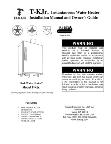
Installation ManualInstallationHIGH-ALTITUDE INSTALLATIONS Adjust the appropriate DIP switches according to model and elevation asshown below. DO NOT adjust the other DIP switches.Turn off the power supply to the water heater before changing the DIPswitch settings.Failure to observe these warnings could lead to carbon monoxide poisoningor death. WARNING Check the elevation where your water heater is installed. Set DIP switches shown in the table belowdepending on the altitude.Indoor modelAltitude0 to 2,000 ft(0 to 610 m)(DEFAULT)1 2 3 4 5 6 7 8 9 10ONOFFDIP switches2,000 to3,000 to5,000 to7,500 to3,000 ft5,000 ft7,500 ft10,100 ft(611 to 914 m) (915 to 1,524 m) (1,525 to 2,286 m) (2,287 to 3,078 m)1 2 3 4 5 6 7 8 9 10ONOFFNo. 3 : OFFNo. 4 : OFFNo. 5 : OFF1 2 3 4 5 6 7 8 9 10ONOFFNo. 3 : OFFNo. 4 : ONNo. 5 : OFFON1 2 3 4 5 6 7 8 9 10OFFNo. 3 : OFFNo. 4 : OFFNo. 5 : ONON1 2 3 4 5 6 7 8 9 10OFFNo. 3 : OFFNo. 4 : ONNo. 5 : ONNo. 3 : ONNo. 4 : ONNo. 5 : ONOutdoor modelAltitude0 to 2,000 ft(0 to 610 m)(DEFAULT)ON1 2 3 4 5 6 7 8 9 10OFFDIPswitchesNo. 3 : OFFNo. 4 : OFFNo. 5 : OFF2,000 to4,000 to4,000 ft6,000 ft(611 to 1,219 m) (1,220 to 1,829 m)ON1 2 3 4 5 6 7 8 9 10OFFON1 2 3 4 5 6 7 8 9 10OFFNo. 3 : OFFNo. 4 : OFFNo. 5 : ONNo. 3 : ONNo. 4 : OFFNo. 5 : ONInstallation altitudeThe maximum certifiedor allowable installedaltitude is 10,100 ft(3,078 m) for indoormodels and 6,000 ft(1,829 m) for outdoormodels.NOTE: The dark squares indicate the correct DIP switch positions.Computer boardBank of DIP switches12Page
Installation ManualInstallationVENTING INSTRUCTIONSIndoor model-General- Improper venting of this appliance can result in excessive levels of carbonmonoxide which can result in severe personal injury or death. Improper installation can cause nausea or asphyxiation, severe injury or deathfrom carbon monoxide and flue gases poisoning. Improper installation will voidWARNING product warranty. When installing the vent system, all applicable national and local codes must befollowed. If you install thimbles, fire stops or other protective devices and theypenetrate any combustible or noncombustible construction, be sure to followall applicable national and local codes.The Indoor model must be vented in accordance with “Venting of Equipment" in the current edition of theNational Fuel Gas Code: ANSI Z223.1/NFPA 54 in the United States and/or Section 8 of the B149.1 NaturalGas and Propane Installation Code in Canada, as well as applicable local building codes.The use of venting materials approved for Category III/IV appliances is recommended whenever possible.However, the Indoor model may also be vented with plastic pipe materials such as ABS, PVC (solid core),CPVC (solid core), or polypropylene. For details, please refer to the Exhaust Vent (ABS, PVC, CPVC, orPolypropylene Vent) Section on p. 18. Vent installations in Canada which utilize plastic vent systems mustuse venting that complies with ULC S636.General rules for venting water heaters: Place the water heater as close as possible to the vent termination.The vent collar of the water heater must be fastened directly to an unobstructed vent pipe.Do not weld the vent pipe to the water heater’s vent collar.Do not cut or alter the vent collar of the unit.The vent must be easily removable from the top of the water heater for normal service and inspection ofthe unit.The water heater vent must not be connected to any other gas appliance or vent stack.Avoid using an oversized vent pipe or using extremely long runs of the pipe unless it is part of an approvedcommon vent system.Air supply pipe can be made of ABS, PVC (solid core), CPVC (solid core), polypropylene, corrugated stainlesssteel, or Category lll / IV stainless steel. Regarding exhaust pipe, refer to pp.18 to 24.Use of cellular core PVC (ASTM F891), cellular core CPVC, or Radel (polyphenylsulfone) in nonmetallicventing systems is prohibited. Covering non-metallic vent pipe and fittings with thermal insulation isprohibited.Sidewall venting is recommended for the Indoor model. Vertical venting (roof termination) is acceptable.The manufacturer recommends running the exhaust vent and the intake pipe as parallel as possible.For rooftop venting, a rain cap or other form of termination that prevents rain water from entering intothe water heater must be installed.Do not terminate vent into a chimney. If the vent must go through the chimney, the vent must run all theway through the chimney with approved vent pipe.The water heater shall not be connected to a chimney flue serving a separate appliance, designed to burnsolid fuel.General rules for vent terminations: Avoid locating the water heater vent termination near any air intake devices. These fans can pick up theexhaust flue products from the water heater and return them to the building. This can create a healthhazard. Locate the vent termination so that it cannot be blocked by any debris, at any time. Most codes requirethat the termination be at least 12 in (305 mm) above grade and anticipated snow level, but the installermay determine if it should be higher depending on the job site condition and applicable codes. A proper sidewall termination is recommended when the water heater is vented through a sidewall. Regarding the clearances from the exhaust termination to the air inlet or opening, refer to pp. 25 to 27.13Page
Installation ManualInstallation-Combustion air supplyThis gas water heater requires an adequate source of clean air for combustion andventilation. Without sufficient air, your water heater may not operate properly andmay emit excessive and abnormal amounts of carbon monoxide which may result inWARNING carbon monoxide poisoning or death. The guidelines in this section apply to installations within the United States. AllU.S. installations must conform to
The principle behind tankless water heaters is simple: *This diagram illustrates tankless water heater design concepts only and does not accurately represent the water heater's physical description. 1. A hot water fixture is turned on. 2. Water flows through the heater. 3. The water flow sensor detects the water flow. 4.