Transcription
T-K3 Instantaneous Water HeaterInstallation Manual and Owner’s GuideWARNINGThis product must be installed andserviced by a licensed plumber, alicensed gas fitter, or a professionalservice technician. Improper installationand/or operation, or installation by anunqualified person, will void thewarranty.WARNINGIf the information in this manual is notfollowed exactly, a fire or explosion mayresult, causing property damage,personal injury, or death.Flash Water Heater Model T-K3Suitable for potable water heating and space heatingTAKAGI Industrial Co. USA Inc.FEATURING 5 WhatneyIrvine, CA 92618Toll Free: (888) 882-5244 USAToll Free: (877) 877-4953 CANADAENDLESS HOT WATERON DEMAND USAGECOMPACT, SPACE SAVINGENERGY CONSERVATIONCOMPUTERIZED SAFETYNO PILOT LIGHT-1-
CONTENTSSPECIFICATIONS .2INTRODUCTION . 3SAFETY GUIDELINES . . 4INSTALLATION . . 5General . 6Accessories . 6Outdoor Installation . 7Indoor Installation . 9Direct Intake Vent System . 10Venting Instructions . 11Gas Supply / Gas Pipe Sizing . 15Water Connections . 17Pressure Relief Valve . 18Electrical Connections . 19Remote Controller Connection . 19Easy Link Multi-System . 20Pump Connection . .23Initial Operation 24NORMAL OPERATION . 25Normal Operation . 25Flow . 26Freeze Protection System 26Temperature Setting . 27Maintenance and Service . 28TROUBLESHOOTING 29WIRING DIAGRAM . 32OPERATING SAFETY 33APPLICATION .35Space Heating . 35Dual-Purpose Heating 36Re-Circulation . 37OPTIONAL ITEMS . 38COMPONENTS DIAGRAM &PARTS LIST . 39OUTPUT TEMPERATURE CHART . 43WARRANTY 44SPECIFICATIONNatural Gas Input(Operating Range)Min: 11,000 Btu/hMax: 199,000 Btu/hLPG Input(Operating Range)Min: 11,000 Btu/hMax: 199,000 Btu/hGas Connection¾” NTPWater Connections¾” NTPWater Pressure15 - 150 psi*Natural Gas PressureInletMin. 5.0” WCMax. 10.5” WCLP GasPressure InletMin. 8.0” WCMax. 13.5” WCManifold PressureNatural: 2.5” WCPropane: 4.4” WCWeight40 lbs.DimensionsH20.5” x W13.8” x D8.5”IgnitionElectric IgnitionSupplyElectricConsumption120VAC (60Hz)Operation92 WStandby6.2 WFreezeProtection111 W*50 psi or above is recommended for maximum flowNOTECheck the rating plate to ensure this productmatches your specifications.Manufacturer reserves the right to discontinue, or change at any time, specifications ordesigns without notice and without incurring obligations.-2-
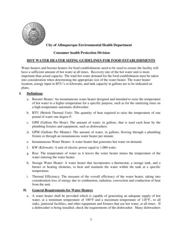
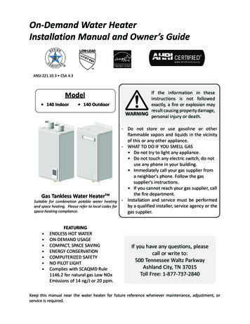
INTRODUCTION This manual provides information necessary for the installation, operation, andmaintenance of the Model T-K3 water heater. The model description is listed on the rating plate which is attached to the front cover ofthe water heater. Please read all installation instructions completely before installing this product. If you have any problems or questions regarding this equipment, consult with Takagi orits local representative. The T-K3 Water Heater is an instantaneous, tankless water heater designed to efficientlysupply endless hot water for your needs. The principle behind the T-K3 Water Heater is simple:1. A hot water tap is turned on.2. Water enters the heater.3. The water flow sensor detects thewater flow.4. The computer automaticallyignites the burner.5. Water circulates through the heatexchanger and then gets hot.6. The computer will modulate thegas supply valve and water flowto produce the right amount of hotwater at the correct temperature.7. When the tap is turned off, theunit shuts down.*This diagram is to illustrate Takagi’s tankless waterheater design concepts only and may not be accurateto the T-K3’s physical description.-3-
SAFETY GUIDELINES Installation and service must be performed by a qualified installer (forexample, a licensed plumber or gas fitter), otherwise the warranty by Takagiwill be void. The installer (licensed professional) is responsible for the correctinstallation of your Flash T-K3 Water Heater and for compliance with allWARNINGnational, state/provincial, and local codes.PLEASE READ THIS MANUAL CAREFULLY AND FOLLOW ALL DIRECTIONS.GENERAL1.Follow all local codes, or in the absence of local codes, follow the most recent edition ofthe National Fuel Gas Code: ANSI Z223.1/NFPA 54 in the USA or CAN/CSA B149.1Natural Gas, Propane Installation Code in Canada.2.Properly ground the unit in accordance with all local codes or in the absence of localcodes, with the National Electrical Codes: ANSI/NFPA 70 in the USA or CSA standardC22.1 Canada Electrical Code Part 1 in Canada.3.Carefully plan where you intend to install your T-K3 Water Heater. Please ensure: Your water heater will have enough combustible air andproper ventilation. Locate your heater where water leakage will not damagesurrounding areas (please refer to p. 5).4.Check the rating plate for the correct GAS TYPE, GASPRESSURE, WATER PRESSURE and ELECTRIC RATING.*If this unit does not match your requirements, do not install andconsult with Takagi.5.RATINGPLATEIf any problem should occur, turn off all hot water taps and turn offthe gas. Then call a trained technician or the Gas Company or themanufacturer.WARNING Water temperatures over 125ºF can cause severe burns instantly or death fromscalding. The water temperature is set at 122ºF (50ºC) from the factory to minimize anyscalding risk. Before bathing or showering always check the water temperature. Prohibited Do not store or use gasoline or other flammables, vapors, or liquids in thevicinity of this appliance.Do not reverse the water and/or gas connections as this will damagethe gas valves and can cause severe injury or death. Follow thediagram on p. 17 when installing your water heater:Do not use this appliance if any part has been in contact with or beenimmersed in water. Immediately call a licensed plumber, a licensed gasfitter, or a professional service technician to inspect and/or service theunit if necessary.Do not disconnect the electrical supply if the ambient temperature will drop belowfreezing. The Freeze Prevention System only works if the unit has electrical power. Thewarranty will not be covered if the heat exchanger is damaged due to freezing. Refer tothe section on the Freeze Prevention System on p. 26 for more information.-4-
INSTALLATIONAll gas water heaters require careful and correct installation to ensure safe and efficientoperation. This manual must be followed exactly. Read the “Safety Guidelines” section at thebeginning of this manual. The warranty will not cover damage caused by water quality. Waterhardness may affect the water heater. Water heater may be damaged. TAKAGI recommends using the Takagi direct vent kit, when the waterCAUTIONheater is installed in a beauty salon. Some chemicals used in a beautysalon may affect the flame sensor. Water heater may not work properly. Although the T-K3 is designed to operate with minimal sound, TAKAGIdoes not recommend installing the unit on a wall adjacent to abedroom, or a room that is intended for quiet study or meditation, etc. Locate your heater close to a drain where water leakage will not do damageto surrounding areas. As with any water heating appliance, the potential forleakage at some time in the life of the product does exist. If there is nodrain, Takagi will not be responsible for any water damage that may occur.If you install a drain pan under the unit, ensure that it will not restrict thecombustion air flow. TAKAGI does not recommend installing unit in an attic due to safetyissues. If you install your T-K3 in an attic:WARNING Make sure your unit will have enough combustion air and properventilation. Keep the area around your T-K3 clean. When dust collects on the flamesensor, the water heater will shut down on errors. If the above conditions cannot be met, use the direct vent conversion kitTK-TV10. Locate unit for easy access for service and maintenance. A drain pan is required to be installed under the water heater in case ofleaks.-5-
GENERAL1. The manifold gas pressure is preset at the factory. It is computer controlled and shouldnot need adjustment.2. Maintain proper space for servicing. Install the unit so that it can be connected orremoved easily. Refer to p. 7 and p. 9 for proper clearances.3. The electrical connection requires a means for switching off the power supply.4. If you will be installing the unit in a contaminated area with a high level of dust, sand,flour, aerosols or other contaminants, they can become airborne and enter and build upwithin the fan and burner causing damage to the unit. In those environments, pleasepurchase the optional TK-TV10 direct vent conversion kit and convert the T-K3 to asealed combustion unit. The warranty will not cover damage caused to the unit due toinstallation in a contaminated environment that has not been converted using the TKTV10.5. Particles from flour, aerosols, and other contaminants may clog the air vent or reducethe functions of the rotating fan and cause improper burning of the gas. Regularly ensurethat the area around the unit is dust- or debris-free; regular maintenance isrecommended for these types of environment.6. Do not install the unit where the exhaust vent is pointing into any opening in a building orwhere the noise may disturb your neighbors. Make sure the vent termination meets therequired distance by local code from any doorway or opening to prevent exhaust fromentering a building (refer to p. 14).ACCESSORIESCheck that the installation manual, the communication cable, and the warranty card areincluded with the unit.-6-
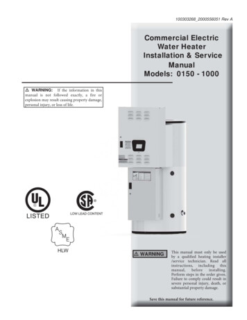
OUTDOOR INSTALLATION1. Follow all local codes, or in the absence of local codes, follow the most recent edition ofthe National Fuel Gas Code: ANSI Z223.1/NFPA 54 in the USA or CAN/CSA B149.1Natural Gas, Propane Installation Code in Canada.2. Outdoor installation only for a mild climate.3. Ensure that the unit is set for outdoor installation. Locate the bank of dipswitches to theright of the 7-Seg. LED on the computer board. The ‘OUT’ dipswitch on the computerboard should be switched to its ‘ON’ (up) position (Do not adjust the bank of dipswitchesabove the LED’s).Make sure power to the unit isturned OFF before changingthe dipswitch settings.The dark square is the directionthe dipswitch should be set to.Burning lamp7-Seg LED4. The outdoor vent cap must be used when unit is installed outdoor. Takagi requires theuse of its part No. TK-TV04.5. When installed outdoors, the T-K3 water heater shall be wall mounted only. Locate thewater heater in an open, unroofed area and maintain the following minimum clearances:Keep the following clearances.-7-
WARNINGDo not install the heater where water, debrisor flammable vapors may get into the flueterminal. This may cause damage to theheater and void the warranty.Do not have the vent terminal pointing towardany opening into a building. Do not locateyour heater in a pit or location where gas andwater can accumulate.ProhibitedProhibitedDo not install this water heater under anoverhang less than 3 feet from its top oreaves. The area under an overhang must beopen to three sides.Do not install the water heater vent terminatorwithin 1 ft. in the USA of any air intake orbuilding opening, and with in 3 ft. in Canadaof any air intake or building opening. (Refer top.14)-8-
INDOOR INSTALLATION1. Follow all local codes, or in theabsence of local codes, followthe most recent edition of theNational Fuel Gas Code: ANSIZ223.1/NFPA 54 in the USA orCAN/CSA B149.1 Natural Gas,Propane Installation Code inCanada.2. When installed indoors, the T-K3water heater shall be located inan area to maintain the followingminimum clearances around theunit:Keep the followingclearances.Combustion Air SupplyThe water heater location must provide enough air for proper combustion and ventilation of thesurrounding area. See the latest edition of ANSI Standard Z223.1 or any applicable local codes.In general, these requirements specify that if the unit is installed in a confined space, there mustbe a permanent air supply opening.Minimum recommended air supply opening size for water heater:Water heater size When drawing make-up air from When drawing make-up air from insideoutside the buildingthe building (from other rooms within)MAX 199,000 BTU13.3 Sq. IN199 Sq. INWhen combustion air is suppliedfrom outside the building, anopening communicating directlywith the outside should have aminimum free area of onesquare inch per 15,000 BTUHinput of the total input rating ofwater heater in the enclosedarea.When combustion air is supplied frominside the building, an openingcommunicating with the rest of thedwelling should have a minimum freearea of one square inch per 1,000BTUH input of the total input rating ofwater heater in the enclosed area.This opening should never be lessthan 199 sq. in.Combustible Air Supplied by Mechanical fan or Make up air deviceThe T-K3 water heater is equipped with a combustible air sensor that will shut off the unit wheninadequate combustible air supply to unit is detected. If a mechanical fan or make up air device is used to supply air to the water heater orutility room, the installer should make sure it does not create drafts which could causenuisance shutdowns. If a blower is necessary to provide adequate combustion air to the water heater, theblower and water heater must be set up so that the water heater cannot fire unless theblower is operating.Possible methods include the use of external flowsensors/transmitters and relays.-9-
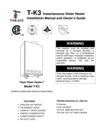
DIRECT INTAKE VENT SYSTEMThis T-K3 water heater may be converted to a direct vent (sealed combustion) appliance byinstalling an adapter (Part No. TK-TV10) which will bring all required combustible air fromoutside the building. The T-K3 must be installed in a location where the proper amount of combustible air willbe available to it at all times without obstructions. If used as a direct vent appliance, the T-K3 requires a 3” combustible air supply pipe.The intake pipe must be sealed airtight. Air supply pipe can be made of ABS, PVC, galvanized steel, corrugated aluminum,corrugated stainless steel or Category III stainless steel. Change the dip switch settings to the direct vent system. Sidewall venting is recommended for the direct vent system. Takagi recommends running the exhaust vent and the intake pipe parallel.Make sure power to the unit isturned OFF before changingthe dipswitch settings.The dark square is the directionthe dipswitch should be set to.Burning lamp7-Seg LEDIntakeTK-TV10 Direct VentConversion Kit- 10 -Exhaust
VENTING INSTRUCTIONSWARNING: Improper venting of this appliance can result in excessive levels ofcarbon monoxide which can result in severe personal injury or death.This water heater must be vented in accordance with the section “Venting of Equipment" of thelatest edition of the Natural Fuel Gas Code: The ANSI Z223.1, All applicable local buildingcodes, Section 7 of the CAN/CSA B149.1 Natural Gas in Canada, Propane Installation Code inCanada.EXHAUST VENTThis is a Category III appliance and must be vented accordingly. The vent system must besealed air tight. All seams and joints without gaskets must be sealed with high-heat resistantsilicone sealant or UL listed aluminum adhesive tape having a minimum temperature rating of350ºF. For best results, a vent system should be as short and straight as possible.1.This Takagi water heater is a Category III appliance and must be vented accordingly withany 4” vent approved for use with Category III or Special BH type gas vent.2.The following are UL listed manufacturers: ProTech Systems Inc. (FasNSeal), Flex-L Inc.,Z-Flex Inc. (Z-Vent III), Metal-Fab Inc., and Heat-Fab Inc. (Saf-T Vent).3.Follow the vent pipe manufacturer’s instructions when installing the vent pipe.4.Do not common vent this appliance with any other vented appliance (Do notterminate vent into a chimney. If the vent must go through the chimney, the vent must runall the way through the chimney with Category III approved or Special BH vent pipe).5.The maximum length of exhaust vent piping must not exceed 50 ft. deducting 5 ft. for eachelbow used in the venting system. Do not use more than 5 elbows.DiameterMax. No. of ElbowMax. Vertical or Horizontal run in Length4”5 Ea.50 ft.*For each elbow added, deduct 5 ft. from max. Vent length.No. of Elbows0125Max. Vertical or Horizontal Length50 ft.45 ft.40 ft.25 ft.6.When the horizontal vent run exceeds 5 ft., support the vent run at 3 ft. intervals withoverhead hangars.7.Takagi will not be responsible for any damage to the water heater caused by condensationfrom the vent. For horizontal runs, slope the vent run downwards toward the vent terminalat a rate of ¼” per foot. For horizontal runs that do not slope downward and for verticalruns, installing a condensate drip is recommended. Please refer to p. 13 for the diagrams.When installing the vent system, all applicable national and local codes must befollowed. If you install thimbles, fire stops or other protective devices and theypenetrate any combustible or noncombustible construction, be sure to follow allapplicable national and local codes.- 11 -
VENT TERMINATIONWARNING: Improper installation can cause nausea or asphyxiation, severe injuryor death from carbon monoxide and flue gases poisoning. Improper installationwill void product warranty. The vent terminator provides a means of installing vent pipe through the building wall andmust be located in accordance with ANSI Z223.1/NFPA 54, or in Canada with CAN/CSAB149.1 and local applicable codes. The sidewall vent terminator, TK-TV01, is recommended when the water heater is ventedthrough a sidewall. Takagi recommends the use of the TK-TV05 with the TK-TV10 when converting to a directvent unit.General rules for venting the T-K3 water heater are:1.Place the water heater as close as possible to the vent terminator.2.The vent collar of the water heater must be fastened directly to an unobstructed vent pipe.3.Do not weld the vent pipe to the water heater collar.4.Do not cut the vent collar of the unit.5.The weight of the vent stack must not rest on the water heater.6.The vent must be easily removable from the top of the water heater for normal service andinspection of the unit.7.The water heater vent must not be connected to any other gas appliance or vent stack.8.Avoid locating the water heater vent terminator near any air intake devices. These fanscan pick up the exhaust flue products from the water heater and return them to thebuilding. This can create a health hazard.9.Avoid using an oversized vent pipe or using extremely long runs of the pipe.10. Locate the vent terminator so that it cannot be blocked by any debris, at any time. Mostcodes require that the terminator be at least 12 inches above grade, but the installer maydetermine if it should be higher depending on the job site condition and applicable codes.11. For rooftop venting, a rain cap must be installed.- 12 -
Regarding the clearance from the terminator to the air inlet or opening, refer to the nextpage. Install a condensation drain in the venting. Follow the vent system to vent manufacturer’s instruction and local code. Do not common vent or connect any vent from other appliances to the T-K3 vent. Use 4” category III approved or Special BH, single or double wall stainless steel ventpipe.- 13 -
CanadaDirect vent andother than DirectVentU.S.ADirect ventOther than Direct Vent1 footAClearance above grade, veranda, porch,deck, or balcony.1 foot1 footBClearance to window or door that may beopened.3 feet1 foot4 feet from below orside opening. 1 footfrom above opening.*Clearance to permanently closed window**Vertical clearance to ventilated soffitlocated above the vent terminator within a***Dhorizontal distance of 2 feet (61cm) fromthe center line of the terminator.***E Clearance to unventilated soffit***F Clearance to outside corner***G Clearance to inside cornerClearance to each side of center line3 feet**Hextended above meter/regulator assemblyClearance to service regulator vent outlet.3 feet**IClearance to non-mechanical air supply4 feet from below or3 feet1 footside opening. 1 footJ inlet to building or the combustion air inletto any other application.from above opening.6 feet3 feet3 feetK Clearance to mechanical air supply inlet.Clearance above paved sidewalk or7 feet*7 feetL paved driveway located on publicproperty.Clearance under veranda, porch deck, or1 foot**Mbalcony.*For clearances not specified in ANSI Z223.1 / NFPA 54 or CAN/CSA-B149.1, please use clearances inaccordance with local installation codes and the requirement of the gas supplier.C- 14 -
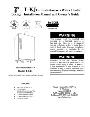
GAS SUPPLY AND GAS PIPE SIZINGTO TURN OFF GAS TO APPLIANCE1. Turn off all electric power to the water heater if service is to be performed.2. Turn the manual gas valve located on the outside of the unit clockwise 3 to the offposition.WARNING: Conversion of this unit from natural gas to propane or vise versacannot be done in the field. Contact your local distributor to get the correct unit foryour gas type. Conversion done by anyone other than the manufacturer will void allwarranty. Takagi is not liable for any property and/or personal damageresulting from unauthorized conversions.*Check that the type of gas matches the rating plate first.1.The minimum and maximum inlet gas pressures are:Natural GasMin. 5.0” WC - Max. 10.5” WCPropane GasMin. 8.0” WC - Max. 13.5” WC2.Gas pressure below this specified range for the T-K3 and/or insufficient gas volume willadversely affect performance.3.Inlet gas pressure must not exceed the above maximum values; gas pressure above thespecified range will cause dangerous operating conditions and damage to the unit.4.Until testing of the main gas line supply pressure is completed, ensure the gas line to theT-K3 is disconnected to avoid any damage to the water heater.MEASURING INLET GAS PRESSUREThe T-K3 cannot perform properly without sufficient inlet gaspressure. Below are instructions on how to check the inlet gaspressure. THIS IS ONLY TO BE DONE BY A LICENSEDPROFESSIONAL.1.Shut off the manual gas valve on the supply gas line.2.Open a faucet. The unit should turn on and the gas in thegas pipe line should purge. Leave the faucet on to keep theunit running until the unit shut down due to lack of gassupply. Then shut the faucet off.3.Remove the screw for the pressure port located on the gasinlet of the T-K3 shown in the diagram to the right.4.Connect the manometer to the pressure port.5.Re-open the manual gas valve. Check to see that there areno gas leaks.6.Open some of the fixtures that use the highest flow rate toturn on the T-K3.7.Check the inlet gas pressure. When T-K3 is on a maximumburn, the manometer should read from 5.0” to 10.5” WC forNatural gas, from 8.0” to 13.5” WC for Liquid Propane.- 15 -
Size the gas pipe appropriately to supply the necessary volume of gas requiredfor the T-K3 (199,000 BTUH for both Natural Gas and Liquid Propane) usingANSI233.1/NAPA 54 in the USA or CAN/CSA B149.1 in Canada or local codes.Otherwise, flow capabilities and output temperatures will be limited.1.Install a manual gas shut-off valve between the T-K3 and the gas supply line.2.When the gas connections are completed, it is necessary to perform a gas leak test eitherby applying soapy water to all gas fittings and observing for bubbles or by using a gas leakdetection device.3.Always purge the gas line of any debris before connecting to the heater gas inlet.Natural Gas Supply PipingMaximum Delivery Capacity of Cubic Feet of Gas per Hour of IPS Pipe Carrying Natural Gas of 0.60 Specific GravityBased on Pressure Drop of 0.5” WCBased on Energy Content of 1100 BTU/Cubic Ft.: T-K3 requires 181 Cubic Ft./hr.Pipe Sizeinches¾”1”1 ¼”1 ½”2”Unit: Cubic Feet per HourLength in 00’ 125’ 23286259239222208197174 1581404 965775663588532490456428404358 3242103 1445 1161 993880798734683641605536 4864050 2784 2235 1913 1696 1536 1413 1315 1234 1165 1033 936200’72135278416801Propane (LP) Gas Supply PipingMaximum Capacity of Propane (LP) Gas Based on 11” WC supply pressure at a 1.0” WC pressure dropUnit: kBTU per HourPipe Sizeinches¾”1”1 ¼”1 ½”2”Length in 00’ 125’ 150’ 200’5673933152672372171961851731621461321121071 7325905044484093783463223072752522132205 1496 1212 1039 9138347717246776305675114403307 2299 1858 1559 1417 1275 1181 1086 1023 9768667876756221 4331 3465 2992 2646 2394 2205 2047 1921 1811 1606 1496 1260- 16 -
WATER CONNECTIONSFOR YOUR SAFETY, READ BEFORE OPERATING:Do not use this water heater if any part has been submersed under water.Immediately call a licensed professional to inspect the water heater and to replaceany damaged parts.1.All pipes, pipe fittings, valves and other components, including soldering materials, mustbe suitable for potable water systems.2.A manual shut off valve must be installed on the cold water inlet to the water heaterbetween the main water supply line and the T-K3.3.In addition, a manual shut off valve is also recommended on the hot water outlet of theunit. If the T-K3 is installed within, or subjected to, a closed loop water system, a thermalexpansion tank must be installed.4.Before installing the water heater, flush the water line to remove all debris, and afterinstallation is complete, purge the air from the line. Failure to do so may causedamage to the heater.5.There is a wire mesh filter within the cold inlet to trap debris from entering your heater. Thiswill need to be cleaned periodically to maintain optimum flow.CAUTION: Do not reverse the hot outlet and cold inlet connections to theT-K3 Water Heater. This will not properly activate the water heater.- 17 -
PRESSURE RELIEF VALVEThe FLASH T-K3 has a high-temperature shut off switch built in as a standard safety feature(called a Hi-Limit switch) therefore a “pressure only” relief valve is required.1.This unit does not come with an approved pressure relief valve.2.An approved pressure relief valve must be installed on the hot water outlet.3.The pressure relief valve must conform to ANSI Z21.22 or CAN 1-4.4 and installation mustfollow local code.4.The discharge capacity must be at least 199,000 BTU/hr.5.The pressure relief valve needs to be rated for a maximum of 150 psi.6.The discharge piping for the pressure relief valve must be directed so that the hot watercannot splash on anyone or on nearby equipment.7.Attach the discharge tube to the pressure relief valve and run the end of the tube to within6" from the floor. This discharge tube must allow free and complete drainage without anyrestrictions.8.If the pressure relief valve installed on the T-K3 discharges periodically, this may be due toa defective thermal expansion tank or defective pressure relief valve.9.The pressure relief valve must be manually operated periodically to check for correctoperation.- 18 -
ELECTRICAL CONNECTIONSWARNING: Follow the electrical code requirements of the local authority havingjurisdiction. In the absence of such requirements, follow the latest edition of theNational Electrical Code ANSI/NFPA 70 in the U.S. or the latest edition of CSAC22.1 Canadian Electrical Code, Part 1, in Canada.CAUTION: When servicing or replacing parts within the T-K3, label all wires prior todisconnection to facilitate an easy and error-free reconnection. Wiring errors cancause improper and dangerous operation. Verify proper operation after servicing.1.The heater must be electrically grounded. Do notattach the ground wire to either the gas or thewater piping.2.The FLASH T-K3 water heater requires AC 120V60 Hz electrical power supply that is properlygrounded. An on/off switch controlling the main power tothe T-K3 must be provided for service reasons; Connect the power supply to the T-K3 exactlyas shown in the wiring diagram;3.A green screw is provided in the junction box toground the connection.4.Can be hardwired or wired to a plug-in.5.The use of a surge protector is recommended inorder to protect the unit from power surges.REMOTE CONTROLLER CONNECTION Minimum 18AWG wire (No polarity) Maximum 400 feet longRemote controller terminalon the computer board Please follow the TM-RE10’s manual.TM-RE10 (Optional)- 19 -
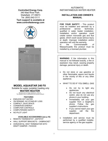
EASY LINK MULTI-SYSTEMThe T-K3 can be connected with other T-K3’s with communication cables to work as a multiplemanifold system. The multi-system can connect up to 4 units. A communication cable (gray color) comes with each unit.You can manifold from 2 units to 4 units without a multi-system controller. A 4-unit system hasfull automatic modulation between 11,000 BTU and 796,000 BTU.HotGasCold The T-K3 multi-system is limited to 4 units. If you connect more than 4 units,the first 4 units will work as a multi-system, but the other units will only work asindividual units.CAUTION The T-K3 cannot link with the other models.Multi-systemOn line lampMulti-system connectors areon each unit’s computer boardMulti-systemConnectorsTo change the dipswitchsettings for a multi-system,locate the bank of dipswitchesto the right of the LED’s.Do not adjust the bank ofdipswitches above the LED’s.PumpConnectors7 Seg LEDDipswitch formulti-system- 20 -
Easy Link Connection Procedures1. Choose one of your units as the MASTER unit.2. The MASTERLocate the bank of dipswitches to the right of the LED’s on the computer board on the MASTERunit. Change dipswitch No.1 to “ON”. Do not change any dipswitch settings of the SLAVE units.3. Between the MASTER and the SLAVE-1Connect the MASTER connector of the MASTER unit to the SLAVE IN connector of the SLAVE1 unit.4. Between the SLAVE-1 and the SLAVE-2Connect the SLAVE OUT connector of the SLAVE-1 unit to the SLAVE IN connector of theSLAVE-2 unit.5. Between the SLAVE-2 and the SLAVE-3Connect the SLAVE OUT connector of the SLAVE-2 unit to the SLAVE IN connector of theSLAVE-3 unit.6. Make s
The T-K3 Water Heater is an instantaneous, tankless water heater designed to efficiently supply endless hot water for your needs. The principle behind the T-K3 Water Heater is simple: *This diagram is to illustrate 1. A hot water tap is turned on. 2. Water enters the heater. 3. The water flow sensor detects the water flow. 4. The .