Transcription
On-Demand Water HeaterInstallation Manual and Owner’s GuideModels 110 310 510510 modelonlyIf the information in theseinstructions is not followedexactly, a fire or explosion mayresult causing property damWARNING age, personal injury or death.--Gas Tankless Water HeaterTMSuitable for potable water heating and space-heating** Please refer to local codes for space-heating compliance. FEATURINGENDLESS HOT WATERON-DEMAND USAGECOMPACT, SPACE SAVINGENERGY CONSERVATIONCOMPUTERIZED SAFETYNO PILOT LIGHTEASY-LINK SYSTEM**(510 models only)-Do not store or use gasoline or other flammable vapors and liquids in the vicinity of thisor any other appliance.WHAT TO DO IF YOU SMELL GAS Do not try to light any appliance. Do not touch any electric switch, do notuse any phone in your building. Immediately call your gas supplier from aneighbor's phone. Follow the gas supplier's instructions. If you cannot reach your gas supplier, callthe fire department.Installation and service must be performed bya qualified installer, service agency or the gassupplier.If you have any questions,please call or write to:GSW Water Heating599 Hill Street WestFergus, ON Canada N1M 2X1Toll Free: 1-888-479-8324320576-000REV. 00 (10-11)
Table of ContentsSPECIFICATIONS . . . . . . . . . . . . . . . . . . . . . . . . . . . . . . . 3INTRODUCTION . . . . . . . . . . . . . . . . . . . . . . . . . . . . . . . . 4SAFETY GUIDELINES. . . . . . . . . . . . . . . . . . . . . . . . . . . . 4Safety Definitions . . . . . . . . . . . . . . . . . . . . . . . . . . . . . 4General . . . . . . . . . . . . . . . . . . . . . . . . . . . . . . . . . . . . . 4INSTALLATION . . . . . . . . . . . . . . . . . . . . . . . . . . . . . . . . . 5General . . . . . . . . . . . . . . . . . . . . . . . . . . . . . . . . . . . . . 5Clearances . . . . . . . . . . . . . . . . . . . . . . . . . . . . . . . . . . 7Included Accessories . . . . . . . . . . . . . . . . . . . . . . . . . . 7Optional Items . . . . . . . . . . . . . . . . . . . . . . . . . . . . . . . . 7High-altitude Installations . . . . . . . . . . . . . . . . . . . . . . 10Venting Instructions. . . . . . . . . . . . . . . . . . . . . . . . . . . 10GeneralExhaust ventingVenting IllustrationsVent Termination ClearancesGas supply and gas pipe sizing . . . . . . . . . . . . . . . . . 15GeneralGas ConnectionsMeasuring Inlet Gas PressureWater Connections . . . . . . . . . . . . . . . . . . . . . . . . . . . 15Pressure Relief ValveElectrical Connections. . . . . . . . . . . . . . . . . . . . . . . . . 16Remote Controller Connections . . . . . . . . . . . . . . . . . 17Pump Control Mode . . . . . . . . . . . . . . . . . . . . . . . . . . 18Easy-link System. . . . . . . . . . . . . . . . . . . . . . . . . . . . . 18GeneralEasy-Link Connection ProceduresAPPLICATIONS . . . . . . . . . . . . . . . . . . . . . . . . . . . . . . . . 20Space-Heating Applications . . . . . . . . . . . . . . . . . . . . 20Recirculation . . . . . . . . . . . . . . . . . . . . . . . . . . . . . . . . 21Dual-purpose Hot Water Heating . . . . . . . . . . . . . . . . 21INITIAL OPERATION . . . . . . . . . . . . . . . . . . . . . . . . . . . . 22OPERATING SAFETY . . . . . . . . . . . . . . . . . . . . . . . . . . . 23NORMAL OPERATION . . . . . . . . . . . . . . . . . . . . . . . . . . 25General . . . . . . . . . . . . . . . . . . . . . . . . . . . . . . . . . . . . 25Temperature Settings . . . . . . . . . . . . . . . . . . . . . . . . . 25Without Remote ControllerDipswitch Settings For TemperatureFlow. . . . . . . . . . . . . . . . . . . . . . . . . . . . . . . . . . . . . . . 26Freeze protection system . . . . . . . . . . . . . . . . . . . . . . 26Maintenance and service . . . . . . . . . . . . . . . . . . . . . . 27Unit Draining and Filter Cleaning2TROUBLESHOOTING . . . . . . . . . . . . . . . . . . . . . . . . . . . 28General . . . . . . . . . . . . . . . . . . . . . . . . . . . . . . . . . . . . 28Error Codes. . . . . . . . . . . . . . . . . . . . . . . . . . . . . . . . . 30Single Unit InstallationsEasy-Link SystemFault Analysis Of Error Codes . . . . . . . . . . . . . . . . . . 31COMPONENTS DIAGRAM . . . . . . . . . . . . . . . . . . . . . . . 34Case Assembly . . . . . . . . . . . . . . . . . . . . . . . . . . . . . . 34110310 & 510Burner Assembly . . . . . . . . . . . . . . . . . . . . . . . . . . . . . 35110310 & 510Computer Board Assembly . . . . . . . . . . . . . . . . . . . . . 37110 & 310Water Way Assembly . . . . . . . . . . . . . . . . . . . . . . . . . 37110Computer Board Assembly . . . . . . . . . . . . . . . . . . . . . 37510Water Way Assembly . . . . . . . . . . . . . . . . . . . . . . . . . 37310Water Way Assembly . . . . . . . . . . . . . . . . . . . . . . . . . 38510Water outlet section . . . . . . . . . . . . . . . . . . . . . . . . . . 38Water inlet section. . . . . . . . . . . . . . . . . . . . . . . . . . . . 38PARTS LIST . . . . . . . . . . . . . . . . . . . . . . . . . . . . . . . . . . . 39OUTPUT TEMPERATURE CHART . . . . . . . . . . . . . . . . . 41110 Models310 Models510 ModelsLIMITED WARRANTY . . . . . . . . . . . . . . . . . . . . . . . . . . . 42
SPECIFICATIONSModel110310510Natural Gas Input(Operating Range)Min.: 19,500 BTU/hMax.: 140,000 BTU/hMin.: 11,000 BTU/hMax.: 190,000 BTU/hMin.: 11,000 BTU/hMax.: 199,000 BTU/hPropane Input(Operating Range)Min.: 19,500 BTU/hMax.: 140,000 BTU/hMin.: 11,000 BTU/hMax.: 190,000 BTU/hMin.: 11,000 BTU/hMax.: 199,000 BTU/hGas Connection3/4” NPTWater Connections3/4” NPTWater Pressure15 - 150 psi*InletPressureNatural GasMin. 5.0” WC, Max. 10.5” WCPropaneMin. 8.0” WC, Max. 14.0” WCManifoldPressure**Natural Gas2.0” WC2.0” WC2.0” WCPropane2.5” WC3.7” WC3.7” WCWeightDimensions13Kg (28.7 lbs.)15.7Kg (34.6 lbs.)520mm(H) x 351mm(W) x 170mm(D)H20.5” x W13.8” x D6.7”520mm(H) x 351mm(W) x D216mm(D)H20.5” x W13.8” x D8.5”IgnitionElectric IgnitionConsumptionElectricSupply120 VAC, 60 HzOperation73.1 W / 0.61 A87.6 W / 0.73 A89.8 W / 0.75 AStandby6.2 W / 0.05 A6.2 W / 0.05 A6.2 W / 0.05 AFreeze-Protection111 W / 0.93 A111 W / 0.93 A111 W / 0.93 A* 40 psi or above is recommended for maximum flow.** The Manifold Pressure is the factory setting and generally should not need adjustment.NOTE: Check the rating plate to ensure this product matches your specifications. The manufacturer reserves the right to discontinue, or change at any time, specifications or designs without noticeand without incurring obligations.3
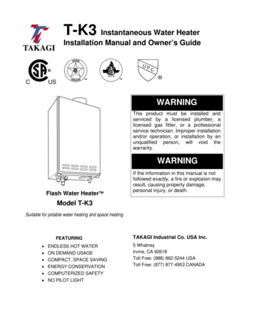
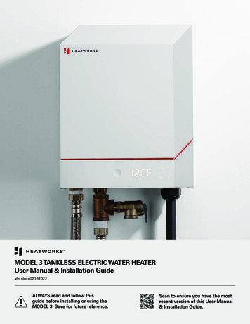
INTRODUCTIONSAFETY GUIDELINES Safety Definitions This manual provides information necessary for theinstallation, operation, and maintenance of the waterheater.The model description is listed on the rating plate whichis attached to the front panel of the water heater.Please read all installation instructions completely beforeinstalling this product.If you have any problems or questions regarding thisequipment, consult with the manufacturer or its localrepresentative.This equipment is an on-demand, tankless water heaterdesigned to efficiently supply endless hot water for yourneeds.The 110, 310, & 510 models are to be installed indoorsonly (direct-vent convertible).The principle behind tankless water heaters is simple:Indicates an imminently hazardous situation which, if not avoided, will result in deathor serious injury.DANGERIndicates an imminently hazardous situation which, if not avoided, could result indeath or serious injury.WARNINGExhaust ventcollarIndicates an imminently hazardous situation which, if not avoided, could result inminor or moderate injury.HeatexchangerCAUTIONGeneralBurnersFlow adjustmentvalveFan motorComputerboardGas ValvesThermistorFlow sensorGasInletHot WaterOutletCold WaterInletThermistor* This diagram illustrates tankless water heater designconcepts only and does not accurately represent to thewater heater’s physical description.1. A hot water tap is turned on.2. Water enters the heater.3. The water flow sensor detects the water flow.4. The computer initiates the fan motor and sends a signalto the igniter to create an ignition spark.5. The gas ignites and flames appear within the burnerchamber.6. Water circulates through the heat exchanger and thengets hot.7. Using thermistors to measure temperatures throughoutthe water heater, the computer modulates the gas andwater valves to ensure proper output water temperature.41. Follow all local codes, or in the absence of local codes,follow the most recent edition of CSA B149.1 NaturalGas and Propane Installation Code.2. Properly ground the unit in accordance with all localcodes or in the absence of local codes, with CSA C22.1Canada Electrical Code Part 1.3. Carefully plan where you intend to install the waterheater. Please ensure: Your water heater will have enough combustible airand proper ventilation. Locate your heater where water leakage will notdamage surrounding areas (please refer to pg. 6).4. Check the rating plate for the correct GAS TYPE,GAS PRESSURE, WATER PRESSURE and ELECTRICRATING.* If this unit does not match your requirements, do notinstall. Consult with the manufacturer.5. If any problem should occur, turn off all hot water tapsand turn off the gas. Then call a trained technician or theGas Company or the manufacturer.
WARNING Water temperatures over 52 C (125 F)can cause severe burns instantly ordeath from scalding. The water temperature is set at 50 C (122 F) from thefactory to minimize any scalding risk.Before bathing or showering alwayscheck the water-temperature.Do not store or use gasoline or otherflammables, vapors, or liquids in thevicinity of this appliance.Do not reverse the water and/or gasconnections as this will damage the gasvalves and can cause severe injury ordeath. Follow the diagram on pg. 17when installing your water heater.Do not use this appliance if any part hasbeen in contact with or been immersedin water. Immediately call a licensedplumber, a licensed gas fitter, or a professional service technician to inspectand/or service the unit if necessary.Do not disconnect the electrical supply ifthe ambient temperature will drop belowfreezing. The Freeze Prevention Systemonly works if the unit has electricalpower. The warranty will not be coveredif the heat exchanger is damaged dueto freezing. Refer to the section on theFreeze Prevention System on pg. 28 formore information.INSTALLATION8. Particles from flour, aerosols, and other contaminantsmay clog the air vent or reduce the functions of the rotating fan and cause improper burning of the gas. Regularlyensure that the area around the unit is dust- or debrisfree; regular maintenance is recommended for thesetypes of environment.9. If you will be installing the water heater in a contaminatedarea with a high level of dust, sand, flour, aerosols orother contaminants/chemicals, they can become airborne and enter and build up within the fan and burnercausing damage to the water heater.10. For the 110, 310, & 510 models: These units may be converted to a direct-vent(sealed combustion) appliance by installing a directvent conversion kit (Part No. TK-TV10) which willbring in all required combustible air from outside thebuilding. When installing the direct-vent conversionkit, please follow all instructions included with the kit. If the water heater is used as a direct-vent appliance,the unit requires a 76mm (3 in.) combustible air supply pipe. The intake pipe must be sealed airtight. Airsupply pipe can be made of ABS, PVC, galvanizedsteel, corrugated aluminum, corrugated stainlesssteel or Category III stainless steel. Terminating the venting through a sidewall is recommended for the direct-vent system. Running the exhaust vent and the intake pipe parallel is recommended. Terminating the exhaust and intake on the samewall/surface is recommended. Terminating in thesame pressure zone allows for pressure balancing,which prevents nuisance shutdowns.General1. Follow all local codes, or in the absence of local codes,follow the most recent edition of CSA B149.1 NaturalGas and Propane Installation Code.2. All gas water heaters require careful and correct installation to ensure safe and efficient operation. This manualmust be followed exactly. Read the “Safety Guidelines”section.3. The manifold gas pressure is preset at the factory. It iscomputer controlled and should not need adjustment.4. Maintain proper space for servicing. Install the unit sothat it can be connected or removed easily. Refer to the"Clearances" section on pg. 7 for proper clearances.5. The water heater must be installed in a location wherethe proper amount of combustible air will be available toit at all times without obstructions.6. The electrical connection requires a means of disconnection, to terminate power to the water heater for servicing and safety purposes.7. Do not install the unit where the exhaust vent is pointinginto any opening in a building or where the noise maydisturb your neighbors. Make sure the vent terminationmeets the required distance by local code from anydoorway or opening to prevent exhaust from entering abuilding (refer to pg. 13).5
WARNING6 Installation and service must be performed by a qualified installer (forexample, a licensed plumber or gasfitter), otherwise the warranty will bevoid.The installer (licensed professional)is responsible for the correct installation of the water heater and for compliance with all national, state/provincial, and local codes.The manufacturer does not recommend installing the water heater in apit or location where gas and watercan accumulate.Do not have the vent terminal pointingtoward any operating window, door, oropening into a building.Do not install next to any source of airborne debris, such as a clothes dryer,that can cause debris to be trappedinside the combustion chamber, unlessthe system is direct-vented.The manufacturer does not recommend installing the water heater in anattic due to safety issues. If you installthe water heater in an attic: Make sure the unit will have enoughcombustion air and proper ventilation. Keep the area around the waterheater clean. When dust collects onthe flame sensor, the water heaterwill shut down on an error code. If the above conditions cannot bemet, use the direct vent conversionkit TK-TV10. Place the unit for easy access forservice and maintenance. A drain pan, or other means of protection against water damage, isrequired to be installed under thewater heater in case of leaks. CAUTION The warranty will not cover damagecaused by water quality. Only potable water or potable water/glycol mixtures can be used withthis water heater. Do not introducepool or spa water, or any chemicallytreated water into the water heater. Water hardness levels must notexceed 7 grains per gallon (120ppm) for single family domesticapplications or more than 4 grainsper gallon (70 ppm) for all othertypes of applications. Water hardness leads to scale formation andmay affect/damage the water heater.Hard water scaling must be avoidedor controlled by proper water treatment. Water pH levels must be between6.5 and 8.5 Well water must be treated.Do not install the unit where water,debris, or flammable vapors may get intothe flue terminal.The manufacturer recommends usingthe direct vent kit when the waterheater is installed in a beauty salon.Some chemicals used in a beauty salonmay affect the flame sensor. Water heater may not work properly.Although the water heater is designed tooperate with minimal sound, the manufacturer does not recommend installing the unit on a wall adjacent to abedroom, or a room that is intendedfor quiet study or meditation, etc.Locate your heater close to a drainwhere water leakage will not do damageto surrounding areas. As with any waterheating appliance, the potential for leakage at some time in the life of the product does exist. The manufacturer will notbe responsible for any water damagethat may occur. If you install a drain panunder the unit, ensure that it will notrestrict the combustion air flow.
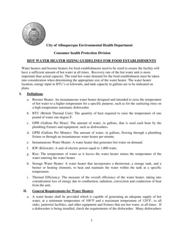
ClearancesOptional PWL4xTK-KPWH4xxxTK-KPCT43xxxBottomMaintain all clearances around the waterheater.ModelTopBottomFrontBackSides110305mm 305mm 610mm(12 in.) (12 in.) (24 in.)25mm(1 in.)51mm(2 in.)310305mm 305mm 610mm(12 in.) (12 in.) (24 in.)25mm(1 in.)51mm(2 in.)510305mm 305mm 610mm(12 in.) (12 in.) (24 in.)25mm(1 in.)51mm(2 in.)Included AccessoriesCheck that these items below are included with the waterheater.ItemsInstallation Manual & Owner’sGuideQty: 1Product Registration CardQty: 1Communication Cable(510 models only)Qty: 17
1. Temperature Remote Controller: TK-RE02The Temperature Remote Controller has two functions. It allows the outputtemperature from the water heater to be adjusted within the range of 37 Cto 75 C (99 F to 167 F), and it also works as a diagnostic tool that will givea concise error code whenever there is a problem with the unit. The temperature options are 75 C (99 F), 38 C (100 F), 39 C (102 F), 40 C (104 F),41 C (106 F), 42 C (108 F), 43 C (109 F), 44 C (111 F), 45 C (113 F), 46 C(115 F), 47 C (117 F), 50 C (122 F), 55 C (131 F), 60 C (140 F), 70 C(158 F), and 75 C (167 F). See the troubleshooting section for informationon possible error codes.2. Temperature Remote Controller: TM-RE30The Temperature Remote Controller has two functions. It allows the outputtemperature from the water heater to be adjusted within the range of 37 Cto 85 C (99 F to 185 F), and it also works as a diagnostic tool that willgive a concise error code whenever there is a problem with the unit. Thetemperature options are 75 C (99 F), 38 C (100 F), 39 C (102 F), 40 C(104 F), 41 C (106 F), 42 C (108 F), 43 C (110 F), 111 F, 45 C (113 F),46 C (115 F), 47 C (117 F), 50 C (122 F), 55 C (131 F), 60 C (140 F), 65 C(149 F), 70 C (158 F), 75 C (167 F), 80 C (176 F) and 85 C (185 F). Seethe troubleshooting section for information on possible error codes.3. Backflow Preventer: TK-BF01The Backflow preventer prevents the backflow of air through the exhaustvent. This helps prevent harmful exhaust gases from entering the home, aswell as helping to prevent the unit from freezing in areas where cold air canbe blown or drawn into the exhaust system. Install this vent damper in accordance with the installation instructions and any applicable codes.4. Direct-Vent Conversion Kit: TK-TV10This kit can be used to convert the water heater from a standard vent systemto a direct-vent (or sealed combustion) system. Install this conversion kit inaccordance with the installation instructions and any applicable codes.5 . Pipe Covers: TK-PC01 and TK-PCJr2The pipe cover protects the plumbing pipes to the water heater from unexpected adjustments. This pipe cover is fixed to the bottom of the water heater,which hides the plumbing and improves the visual aspects of the wholeinstallation for the water heater.8
6. Recess box: TK-RB02The Recess box will allow for “clean” installations. The water heater fits insidethe recess box, which hides and protects the whole water heater and plumbing. The Recess box will fit in-between most wall studs.7. T-Vent Wall Thimble with Termination: TK-KPWL4 and TK-KPWH4These terminations are used when venting out through the wall and are compatible with the T-Vent pipe system. These terminations are special stainlesssteel vents for gas appliances and are UL listed as Category II, III and IV.There are two types of terminations: the Louver termination and the Hoodtermination. For different wall thicknesses, there are two ranges of lengthsavailable (refer to the venting brochure for details). Install these vent terminations in accordance with their installation instructions and any applicablelocal codes.Louver TerminationTK-KPWL4Hood TerminationTK-KPWH48. Direct-Vent Concentric Termination: TK-KPCT43Used when terminating direct-vent (sealed-combustion) systems, with directvent models that require a 76mm (3 in.) intake and a 102mm (4 in.) exhaust.This concentric termination provides the convenience of only having to makeone penetration through a sidewall instead of two separate penetrationsfor the intake and exhaust piping. The termination includes a bird screen,restricting small animals, pests, and foreign objects from entering into thevent system. This sidewall termination is available in three different sizes, tocover all ranges of wall thicknesses.Direct-vent Concentric TerminationPart#Covering wall thicknessTK-KPCT43-199 - 180mm (3.9 – 7.1 in.)TK-KPCT43-2175 - 257mm (6.9 – 10.1 in.)TK-KPCT43-3 249 - 330mm (9.8” – 13.0 in.)9
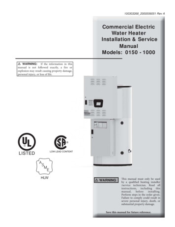
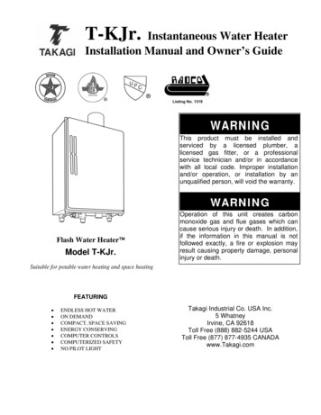
High-altitude InstallationsCheck the elevation where your water heater is installed.Set DIPswitches shown in the table below depending onthe altitude.110 & 310 ModelsCAUTION0 toAltitude2,000 ft(DEFAULT)2,000 to4,000 ft4,000 to6,000 ftOver6,000 ftConsultourTechnicalServicesat 1-888479-8324SwitchNo. 3OFFONOFFSwitchNo. 4OFFOFFON1 2 3 4 5 6 7 8ON1 2 3 4 5 6 7 8ON1 2 3 4 5 6 7 8ON510 Models (Left bank of DIPswitches)Altitude0 to2,000 ft(DEFAULT)2,000 to4,000 ft4,000 to6,000 ftOver6,000 ftSwitchNo. 4OFFONOFFSwitchNo. 5OFFOFFONConsultourTechnicalServicesat 1-888479-83241 2 3 4 5 6ON 1 2 3 4 5 6ON1 2 3 4 5 6ONThe dark squares indicate the direction the DIPswitchesshould be set to.110 & 310 Computer boardDIPswitches510 Computer boardWARNINGVenting InstructionsGeneral DANGER10The water heater must be vented in accordance with thesection “Venting of Equipment" of the latest edition of CSAB149.1 Natural Gas and Propane Installation Code aswell as applicable local building codes.The manufacturer recommends the “T-Vent” line manufactured by TAKAGI (Refer to “T-Vent” brochure for details).However, the following are also UL listed manufacturers:ProTech Systems Inc. (FasNSeal), Flex-L Inc., Z-Flex Inc.(Z-Vent III), Metal-Fab Inc., and Heat-Fab Inc. (Saf-T Vent).General rules for venting water heaters are: Place the water heater as close as possible to the ventterminator. The vent collar of the water heater must be fasteneddirectly to an unobstructed vent pipe. Do not weld the vent pipe to the water heater’s vent collar. Do not cut the vent collar of the unit. The vent must be easily removable from the top of thewater heater for normal service and inspection of theunit. The water heater vent must not be connected to anyother gas appliance or vent stack. Avoid using an oversized vent pipe or using extremelylong runs of the pipe. For rooftop venting, a rain cap or other form of termination that prevents rain water from entering into the waterheater must be installed. Do not common vent or connect any vent from otherappliances to the water heater vent.DIPswitches (Left bank)DO NOT adjust any DIPswitches on theright bank for the 510 models. When installing the vent system, all applicable national and local codes must befollowed. If you install thimbles, fire stopsor other protective devices and they penetrate any combustible or noncombustibleconstruction, be sure to follow all applicablenational and local codes.Improper venting of this appliance canresult in excessive levels of carbonmonoxide which can result in severepersonal injury or death.Improper installation can cause nauseaor asphyxiation, severe injury or deathfrom carbon monoxide and flue gasespoisoning. Improper installation will voidproduct warranty.General rules for vent terminations: Avoid locating the water heater vent terminator near anyair intake devices. These fans can pick up the exhaustflue products from the water heater and return them tothe building. This can create a health hazard. Locate the vent terminator so that it cannot be blocked byany debris, at any time. Most codes require that the terminator be at least 305mm (12 in.) above grade, but theinstaller may determine if it should be higher dependingon the job site condition and applicable codes. A proper sidewall terminator is recommended when thewater heater is vented through a sidewall. Regarding the clearances from the exhaust terminator tothe air inlet or opening, refer to the next few pages.
Exhaust venting(For the 110, 310, & 510 models)This is a Category III appliance and must be vented accordingly. The vent system must be sealed air tight. All seamsand joints without gaskets must be sealed with high heatresistant silicone sealant or UL listed aluminum adhesive tape having a minimum temperature rating of 177 C(350 F). For best results, a vent system should be as shortand straight as possible. This water heater is a Category III appliance and must bevented accordingly with any 102mm (4 in.) vent approvedfor use with Category III or Special BH type gas vent. Follow the vent pipe manufacturer’s instructions wheninstalling the vent pipe. Do not common vent this appliance with any other ventedappliance (Do not terminate vent into a chimney. If thevent must go through the chimney, the vent must run allthe way through the chimney with Category III approvedor Special BH vent pipe). When the horizontal vent run exceeds 1.5m (5 ft.), support the vent run at 0.9m (3 ft.) intervals with overheadhangars. The maximum length of exhaust vent piping must notexceed 15.24m (50 ft.) (deducting 1.5m (5 ft.) for eachelbow used in the venting system). Do not use more than5 elbows.DiameterMax. No. ofElbowMax. Vertical &Horizontal (Total) VentLength76mm (3 in.)515.24m (50 ft.)Venting Illustrations(For the 110, 310, & 510 models)For details of the optional items, refer to the Optional itemlist.Horizontal Installation venter*Sidewall VentTerminatorVertical Installation DiagramRoofRain CapRoof Flashing* For each elbow added, deduct 1.5m (5 ft.) from max.vent length.No. ofElbowsMax. Vertical or Horizontal Length015.24m (50 ft.)113.7m (45 ft.)212.2m (40 ft.)57.6m (25 ft.)Excludes elbow termination, rain caps, or the 76mm (3in.) PVC Concentric rain**11
Horizontal Installation Diagram (with direct-venting)WallHorizontal Installation Diagram With Direct-Vent **Sidewall VentTerminatorBackflowPreventer*See the picture below fordetailed connection instructionsto the Direct-Vent Conversion Kit.Vertical Installation Diagram (With direct-venting)Direct-vent ConcentricTerminationRoof FlashingRain CapRoofRoof FlashingInstallation Diagram of Direct-Vent Conversion Kit withwater heaterIntake port ofDirect-VentConversion e the picture below fordetailed connection instructionsto the Direct-Vent Conversion Kit.* Backflow Preventer (Recommended for freezing weatherconditions: 2 C (36 F) and below).** Vertical Condensation Drain must be installed accordance with local codes.12Plate of Direct-VentConversion Kit
Vent Termination ClearancesCanadaU.S.ADirect vent and otherthan Direct VentDirectventOther thanDirect VentAClearance above grade, veranda, porch, deck, or balcony.1 foot1 foot1 footBClearance to window or door that may be opened3 feet1 foot4 feet from below orside opening. 1 footfrom above opening.CClearance to permanently closed window***DVertical clearance to ventilated soffit located above thevent terminator within a horizontal distance of 2 feet(61cm) from the center line of the terminator.***EClearance to unventilated soffit***FClearance to outside corner***GClearance to inside corner***HClearance to each side of center line extended abovemeter/regulator assembly3 feet**IClearance to service regulator vent outlet.3 feet**JClearance to non-mechanical air supply inlet to building orthe combustion air inlet to any other application3 feet1 foot4 feet from below orside opening. 1 footfrom above opening.KClearance to mechanical air supply inlet.6 feet3 feet3 feetLClearance above paved sidewalk or paved drivewaylocated on public property.7 feet*7 feetMClearance under veranda, porch deck, or balcony.1 foot*** For clearances not specified in CSA B149.1 Natural Gas and Propane Installation Code, please use clearances inaccordance with local installation codes and the requirement of the gas supplier.13
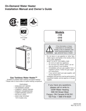
Please follow all local and national codes inregards to proper termination clearances.In the absence of such codes, the following clearances can be used as guidelines.Local codes supersede these guidelines.CAUTIONFor rooftop terminationsAAAFor sidewall terminationsm305m(1 ft.)m610m(2 ft.)m305m(1 ft.)stExhauationtermin3 ft.3 ft.Exhaustterminationm305m(1 ft.)t ventDirec wallexhaust terminations (e.g.multi-unit systems), anexhaust termination mustbe at least 305mm (1 ft.)away from another exhausttermination. An exhaust termination must also be atleast 610mm (2 ft.) awayfrom an inside corner (if theadjacent wall is less than610mm (2 ft.) of length, theminimum required distanceaway from the inside cornerwill be equal to the length ofthat adjacent wall).For multiple-unit, directvent sidewall terminationsthat combine the intakeand exhaust into a singlepenetration, space eachdirect-vent termination atleast 305mm (1 ft.) awayfrom each other, no matterthe orientation. A direct-venttermination must also be atleast 610mm (2 ft.) awayfrom an inside corner (if theadjacent wall is less than610mm (2 ft.) of length, theminimum required distanceaway from the inside cornerwill be equal to the length ofthat adjacent wall).2 ft.3 ft.Air supply inletFor direct-vent sidewall terminations that use two separate penetrations for theintake and exhaust, distancethe intake and exhaust terminations at least 915mm(3 ft.) away from each other,no matter the orientation.14Airintake10mmm 6 (2ft.)305m.)ft(1ExhaustterminationExhaust and/or direct-ventsidewall terminations shouldbe at least 610mm (2 ft.)away from an opposite surface/wall. Do not place thetermination directly in frontof an opening into a building.Airintake610mm(2 ft.)AAExhaustterminationA: In accordance with local codesFor multiple-unit rooftop terminations (whether for
* This diagram illustrates tankless water heater design concepts only and does not accurately represent to the water heater's physical description. A hot water tap is turned on. Water enters the heater. The water flow sensor detects the water flow. The computer initiates the fan motor and sends a signal to the igniter to create an ignition spark.