Transcription
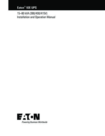
OPERATION AND INSTALLATIONOPERACIÓN E INSTALACIÓNUTILISATION ET INSTALLATIONTANKLESS ELECTRIC WATER HEATERS CALENTADORES DE AGUA SIN TANQUE CHAUFFE-EAUINSTANTANÉS ÉLECTRIQUESTankless Electric Water Heaterwith electronic temperature controlesidential Use RHandWas12 B15 B20 B24 B29 B36 B12 PLUS15 PLUS20 PLUS24 PLUS29 PLUS36 PLUSComSC mAghinLDITEMPRA TEMPRA TEMPRA TEMPRA TEMPRA TEMPRA TEMPRA TEMPRA TEMPRA TEMPRA TEMPRA TEMPRA nlylOcia NGERerNG DA F CBlinking: maximum power,less than set point temp.Steady: unit operatingOff: unit offTankless Electric Water Heaterwith electronic temperature controlPowerential UseResidghinComSC mALDINlyl Oncia GERer G DANHandWas»»»»»»»»»»»»On: unit operatingOff: unit offMade in GermanyConforms to ANSI/UL Std. 499Certified to CAN/CSA Std. E335-1 & E335-2-35Conforme a ANSI/UL Std. 499Certificación con CAN/CSA Std. E335-1 & E335-2-35Conforme à la norme ANSI/UL Std. 499Certifié à la norme CAN/CSA Std. E335-1 & E335-2-35Tested and certified by WQA to NSF/ANSI 372for lead free compliance.Probado y certificado por WQA NSF/ANSI 372 parael cumplimiento de las regulaciones sin plomo.Testé et certifié par WQA à la NSF/ANSI 372 pour uneutilisation sans plomb.
CONTENTS OPERATIONOPERATION1.General Information 22.2.12.22.32.4Safety 2Intended use 2General Information 2Safety Precautions 3Test symbols 33.Register your product 34.4.14.2General 3General appearance 4Tempra B units: 4INSTALLATION5.Installation configuration 56.Mounting the unit 57.Water connections 68.8.18.28.3Electrical connection 6Circuit Layout 6Circuit Connection 7Terminal block 89.Initial settings 810.Commissioning the water heater 811.Normal maintenance 812.Troubleshooting 913.13.113.213.313.413.5Technical Data 9Tempra B 9Tempra Plus 10Temperature increase above ambient water temperature11Dimensions 12Wiring Diagrams 1314.Spare parts 1415.Warranty 16OPERATION1.General InformationRead this entire manual. Failure to follow all the guides, instructions and rules could cause personal injury or property damage.Improper installation, adjustment, alteration, service and use ofthis unit can result in serious injury.This unit must be installed by a licensed electrician and plumber.The installation must comply with all national, state and localplumbing and electric codes. Proper installation is the responsibility of the installer. Failure to comply with the installation andoperating instructions or improper use voids the warranty.Save these instructions for future reference. Installer should leavethese instructions with the consumer.If you have any questions regarding the installation, use or operation of this water heater, or if you need any additional installationmanuals, please call our technical service line at 800-582-8423(USA and Canada only). If you are calling from outside the USA orCanada, please call USA 413-247-3380 and we will refer you to aqualified Stiebel Eltron service representative in your area.!2.This is the safety alert symbol. It is used to alert you topotential personal injury hazard. Obey all safety messages that follow this symbol to avoid possible injuryor death.SafetyObserve the following safety information and regulations.Operate the appliance only when fully installed and with all safetyequipment fitted.2.1Intended useThe appliance is intended for heating domestic hot water and cansupply several draw-off points.Any other use beyond that described shall be deemed inappropriate.Observation of these instructions is also part of the correct useof this appliance.2.2General InformationRead this entire manual. Failure to follow all the guides, instructions and rules could cause personal injury or property damage.Improper installation, adjustment, alteration, service and use ofthis appliance can result in serious injury.This appliance must be installed by a licensed electrician andplumber. The installation must comply with all national, state andlocal plumbing and electric codes. Proper installation is the responsibility of the installer. Failure to comply with the installationand operating instructions or improper use voids the warranty.Save these instructions for future reference. Installer should leavethese instructions with the consumer.2 TEMPRA & TEMPRA PLUSWWW.STIEBEL-ELTRON-USA.COM
OPERATIONREGISTER YOUR PRODUCT2.3!!!Register your productYou must register this product within 90 days of purchase on our web site in order to activate the standardwarranty or to be eligible for the extended warranty.Go to our web site atwww.stiebel-eltron-usa.com and click on registeryour product.Safety PrecautionsDANGER: InjuryPlease read and follow these instructions. Failure tofollow these instructions could result in serious personal injury or death.Damage to the appliance and the environmentThe appliance must be installed by a licensed electricianand plumber. The installation must comply with all national, state and local plumbing and electric codes.Service of the appliance must be performed by qualifiedservice TECHNICIANS.Before beginning the registration process, we suggest thatyou gather the necessary information which will be asfollows:DANGER: ElectrocutionBefore proceeding with any installation, adjustment.Alteration, or service of this appliance all circuitbreakers and disconnect switches servicing the appliance must be turned off. Failure to do so could resultin serious personal injury or death.Type, Example: Tempra 24 Plus (from the label that is on theunit)Number listed after “Nr.”Place of PurchasePurchase DateFirst & Last NameEmail addressPhysical AddressPhone NumberInstallation DateDANGER: ElectrocutionNever remove the appliance‘s cover unless the electricity servicing the appliance is turned off. Failure todo so could result in personal injury or death.IF YOU HAVE ANY QUESTIONS CONCERNING THE REGISTRATION PROCESS OR WARRANTY OPTIONS, PLEASE CONTACTSTIEBEL ELTRON USA DIRECTLY AT (800)-582-8423.DANGER: ElectrocutionThe appliance must be properly grounded. Failure toelectrically ground the product could result in seriouspersonal injury or death.DANGER: BurnsWater temperatures over 125 F (52 C)can causesevere burns instantly or death from scalding. A hotwater scalding potential exists if the thermostat onthe appliance is set too high. Households with smallchildren, disabled or elderly persons may require thatthe thermostat be set at 113 F (45 C) or lower toprevent possible injury from hot water.WARNING: Injurywhere children or persons with limited physical, sensory or mental capabilities are to be allowed to control this appliance, ensure that this will only happenunder supervision or after appropriate instructions bya person responsible for their safety. Children shouldbe supervised to ensure that they never play with theappliance.2.43.Test symbolsSee the type label on the appliance.4.General!DANGER: BurnsWater temperatures over 125 F (52 C) can causesevere burns instantly or death from scalding. A hotwater scalding potential exists if the thermostat on theappliance is set too high. Households with smallchildren, disabled or elderly persons may require thatthe thermostat be set at 113 F (45 C) or lower toprevent possible injury from hot water.The Tempra B and Tempra Plus units are designed to supply hotwater for a house, apartment or certain commercial applications.Unlike a conventional storage type water heater the Tempra tankless water heater does not store hot water. Instead, water is heatedinstantaneously as it flows through the unit. The Tempra offersgreater energy efficiency than storage type water heaters due tothe absence of stand-by losses and reduced hot water pipe runs.The input of heat into the water is controlled electronically. TheTempra will deliver any water temperature between 86 F (30 C)and 140 F (60 C). Please set the desired temperature using theknob on the front cover. The Tempra Plus Temperature adjustmentknob can be set to: OFF, 86.140 F (30.60 C).The Tempra B has a F and a C scale. The output temperature ofthe Tempra Plus is shown in the digital display in F or C units.( F or C units can be selected during installation, factory setting: F). The maximum temperature is electronically limited to 140 F(60 C).WWW.STIEBEL-ELTRON-USA.COMTEMPRA & TEMPRA PLUS 3ENGLISHIf you have any questions regarding the installation, use or operation of this water heater, or if you need any additional installationmanuals, please call our technical service line at (800)-582-8423.
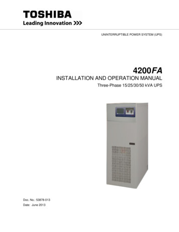
OPERATIONGENERALFor reasons of appliance efficiency and durability (scaling), theoptimum temperature setting lies between 86 F (30 C) and120 F (50 C).The outlet temperature of the Tempra Plus can be limited (see"Initial settings").4.1General appearance4.2Tempra B units:In case the "Power” LED is flashing while the unit operates, thewater flow rate exceeds the heating capacity of the unit. Reducethe hot water flow rate in order to let the unit achieve the setpoint temperature.!In case you have questions regarding the way youplan to use the Tempra unit, please call our technicalservice line at 800-582-8423 (USA and Canada). Forservice outside the U.S. and Canada, please call us at413-247-3380. You can also e-mail us atinfo@stiebel-eltron-usa.com or fax us at413-247-3369.Tankless Electric Water Heaterwith electronic temperature controlLDI12ComSC mAnlylOcia NGERerNG DAHandWasesidential Use Rghin F C3Blinking: maximum power,less than set point temp.Steady: unit operatingOff: unit offTankless Electric Water Heaterwith electronic temperature control32.1PowerComSC mALDINlyl Oncia GERer G DANHandWasential UseResidghin1On: unit operatingOff: unit offMade in Germany1 Temperature adjustment knob2 Temperature scale2.1 Temperature display3 "Power" light4 TEMPRA & TEMPRA PLUSWWW.STIEBEL-ELTRON-USA.COM
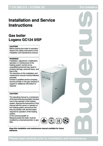
INSTALLATIONINSTALLATION CONFIGURATION5.ENGLISHINSTALLATIONInstallation configurationThe Tempra can be used for the following 415151616171718181919202021212222232324246.Typical residential installationTypical commercial installation12314by124. Mount unit securely to wall puttingat least three screwsthrough mounting holes 1 2 3 . Screws and plastic wallanchors for mounting on masonry2 3 4 or wood1 are Mounting the unit2789 10NOTICE: Unit must be installed in a vertical positionwith the water fittings pointing downward.3910 11AB4WARNING: Do not install unit where it would routinelybe splashed with water. Electric shock may result.CAUTION: Hot water outlet pipes leaving unit can behot to the touch. Insulation must be used for hot waterpipes below 36" due to burn risk to children.NOTICE: This unit should not be installed in a locationwhere it may be exposed to freezing temperatures(less than 36 F). If the unit may be subject to freezingtemperatures all water must be drained from the unit.Failure to comply with this instruction voids all warranties.56C712⅜ / 10 mmB12½ / 318 mmC111 / 26 mmCAUTION: Hot water outlet pipes leaving unit can behot to the touch. Insulation must be used for hot waterpipes below 36" due to burn risk to children.D¾ / 19.512mmE7½ / 190 mmF7½ / 190 mmG3/16 1012 13 143415 16 17517 18 198E 6Dimensions97A11 12 1313 14 15DThe unit should be located in an area where waterleakage from the unit or connections will not result indamage to the area adjacent to the unit. If such a location cannot be avoided it is recommended that a drainpan be installed under the unit.10 11 128914 15 1616 17 1818 19 2019 20 2120 21 2221 22 2322 23 2423 24242345678910F111213141013151114/ 5 mm16121517132. Leave a minimum of 5" of clearance on all sides for servicing.16183. Remove the cover screw with a #2 Pozi-drive screwdriver andopen the cover .141719151820161921172018Install Tempra as close as possible to the main hot water drawoff points.1. Install Tempra in a frost free area. If frost might occur, remove unit before freezing temperatures set in.WWW.STIEBEL-ELTRON-USA.COMG22& TEMPRA PLUS 5TEMPRA23
INSTALLATIONWATER CONNECTIONS7.8.Water connections!NOTICE: Excessive heat from soldering on copper pipesnear the tempra may cause damage.Electrical connection!The cold water connection to the unit must be disconnected periodically in order to clean the filter screen.It is required to use water connections that are easilydetachable such as braided steel flex connectors.!NOTICE: Hard water or water with a high mineralcount may damage the unit. Damage to the unit causedby scale or a high mineral count is not covered underthe warranty.The unit must be properly grounded in accordancewith state and local codes, or in absence of suchcodes, in accordance with national electric code or theCanadian electric code. Failure to electrically groundthe product could result in serious personal injury ordeath.1. All plumbing work must comply with national and applicablestate and local plumbing codes.2. A pressure reducing valve must be installed if the cold watersupply pressure exceeds 150 PSI (10 bar).3. Make certain that the cold water supply line has been flushedto remove any scale and dirt.1 that should be1 to time. Clean screen and put the screencleaned from time2and the washer 2 back into their original position.34. The Tempra unit has a built in filter screen3The Tempra should be connected to properly grounded dedicatedbranch circuits of proper voltage rating. Ground must be broughtto the "Ground" at the circuit breaker panel.8.1Circuit Layout8.1.1 Tempra 12 B / Tempra 12 Plus44667788991010111111212132131141526 02 02 08775514WARNING: Before beginning any work on the electricinstallation, be sure that main breaker panel switches are "off" to avoid any danger of electric shock. Allmounting and plumbing must be completed beforeproceeding with electrical hook-up. Where requiredby local, state or national electrical codes the circuitsshould be equipped with a "ground fault interrupter".165. The cold water(inlet) is on the rightside of the3217 on the left side16unit, and the hot water connection (outlet) isof the unit.181715connection4!319 the TEMPRA18NOTICE: Tanklesswater heaters such asare not requiredtobeequippedwitha20pressure and4 local5 1920relief valve (P&T). If thetemperatureinspector21will not pass the installation without a P&T, it should22 of the unit.be installed21on the hot water outlet5sideCKT 1ONON26 02 02 0568OFFOFF62322 hot side is designed for connection6. The Tempra on theto62423copper7 tubingtubing, PEX24 or a braided stainless steel hose with a73/4" NPT female tapered thread.The plumbing8 on the cold water inlet side needs to be suchthat8it can easily be removed to allow access to the inlet filter9screen.9The easiest way to achieve this is to us a stainless steel10 connector.braided hose10If soldering near the unit is necessary, please direct theflame away11from the housing of the unit11in order to avoiddamage.Tempra 12 B/Plus: These units can be connected to a single circuit. Usea supply cable protected by a double pole breaker.7. When all12plumbing work is completed, 12check for leaks andtake corrective action before proceeding.6 TEMPRA13& TEMPRA PLUS1314WWW.STIEBEL-ELTRON-USA.COM
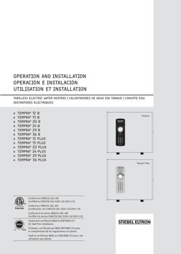
INSTALLATIONELECTRICAL CONNECTION8.1.3 Tempra 29, 36 B / Tempra 29, 36 PlusCKT 126 02 02 0881ENGLISH8.1.2 Tempra 15, 20, 24 B / Tempra 15, 20, 24 PlusCKT 2ONONONOFFOFFOFFONOFFONOFF26 02 02 056826 02 02 0568Tempra 15, 20 or 24 B/Plus: These units require two independentcircuits. Use two supply cables protected by two separate doublepole breakers.ONOFFONONONONOFFOFFOFFOFFCKT 1 CKT 2 CKT 3Tempra 29 or 36 B/Plus These units require three independent circuits.Use three supply cables protected by three separate double polebreakers.8.2Circuit ConnectionPlease refer to the technical data table for the correct wire andcircuit breaker size. In all cases, make sure that the unit is properlygrounded.1. Cut the electrical connection cable to length and strip.26 02 02 089315 (380mm)The wire must be fed through the knock-outs located betweenthe hot and cold water connections (See 8.1, “Circuit Layout”,pg. 6). The "live" wires must be connected to the slots on theterminal block marked L1 and L2. The ground wire must be connected to slot marked with the ground symbol (See 13.5, “WiringDiagrams”, pg. 13 ).WWW.STIEBEL-ELTRON-USA.COMTEMPRA & TEMPRA PLUS 7
INSTALLATIONINITIAL SETTINGS8.3Terminal blockWe recommend using stranded wire to connect to the terminalblock. Crimp a ferrule over stranded bare wire to ensure a goodconnection.Consult the chart below for the recommended torque amounts onthe terminal block screws.Screw Diameter e (N cm) Torque (lbf 13.27-17.7Using the proper torque specifications to secure wire to the wiringblock helps to avoid personal loss or property damage.See 13, “Technical Data”, pg. 9 for information on the properwire gauge size.9.Initial settingsCheck whether the set value transducer cable is plugged into theslot TSoll A1 (Tempra B) or TSoll D (Tempra Plus) on the main PCB.2. Select a specific outlet temperature- Switch the appliance 'live'.- Open the casing so that coding plug Tmax / Tred becomesaccessible.- Set the temperature selector to "OFF". The coding plug mustbe set to Tmax (standard delivery).- Set coding plug to Tred; the setting mode will be activated andthe flashing display shows the current temperature limit.- Within the next 30 seconds, you can select the requiredtemperature (display continues to flash). The setting modewill terminate after 30 seconds; the programming unit willdisplay "OFF" again.10. Commissioning the water heater!WARNING: Open hot water faucet for a few minutesuntil water flow is continuous and all air is purgedfrom water pipes. The unit’s cover must be installedbefore the circuit breakers are turned on.1. Close the cover and fix it using the screw with the lockwasher.2. Turn on circuit breakers to bring electrical power to the unit.3. Turn the temperature selector clockwise and anti-clockwise,to calibrate the set value transducer.4. Adjust the water temperature to the desired level using theknob on the front cover of the unit.5. Turn on hot water and wait twenty seconds until temperaturehas stabilized.6. Check the water temperature with your hand and make surethat it does not feel too hot. Reduce if necessary.7. Explain to the user how the unit works and familiarize himor her with its use.Advise the user about possible hazards (hot water temperature up to 140 F / 60 C). Hand over these instructions, to bekept for future reference.1231425- 1 Selection of F3 or C units62- Set1 jumper on the dial-printed circuit board to F or C.43- 2 Activate anti-scaldingprotection function743On theTempra Plus,5 an anti-scalding protection function can be584activatedby two differentmethods.661. Limitthe outlet temperatureto the fixed temperature of5791096 F (43 C).877- Insertthe coding10plug into position Tred (reduced9temperature).8810119118 10TEMPRA & TEMPRAPLUS91212111311. Normal maintenance!NOTICE: The Tempra does not contain any parts serviceable by the average user. In case of malfunctionplease contact a licensed plumber or electrician.Stiebel Eltron Tempra tankless water heaters are designed for avery long service life. Actual life expectancy will vary with waterquality and use. The unit itself does not require any regular maintenance. However, to ensure consistent water flow, it is recommended to periodically remove scale and dirt that may build upat the aerator of the faucet(s), the filter screen in the unit, or inthe shower head.WWW.STIEBEL-ELTRON-USA.COM
INSTALLATIONTROUBLESHOOTINGSymptomNo hot waterPossible cause– circuit breakers off– safety thermal cut-out tripped– not enough flow rate to activate unitNot enough hot waterWater not hot enough– filter screen clogged– water flow rate too high– voltage too lowSolution– turn circuit breakers on– reset safety thermal cut-out– clean filter screen at unit– clean faucet aerator or shower head– clean filter screen at unit– reduce water flow rate until power light on front cover stops blinking– supply correct voltage to unitIf you are not able to resolve a problem please contact us toll free at 800-582-8423 before removing the unit from the wall.Stiebel Eltron is happy to provide technical assistance. In most instances, we can resolve the problem over the phone.13. Technical Data13.1 Tempra BPart numberElectrical detailsPhaseVoltageWattageMax. amp. loadNumber & min. recommended size of circuitbreakers1 (DP)Power connectionMin. recommended wire size (copper)2ConnectionsWater connectionMax. cold water temperatureHydraulic dataRated capacityValuesONONMax. permissible inlet temperatureApplication limitsMax. permissible pressureTest pressureVersionsTemperature displayCap and back Tempra 12 B223420Tempra 15 B223421Tempra 20 B223422Tempra 24 B3223424Tempra 29 B4232885Tempra 36 B5232886single 50/60 Hz240 V208 V12 kW9 kW1 x 50 A 1 x 44 Asingle6 50/60 Hz240 V208 V14.4 kW 10.8 kW2 x 30 A 2 x 26 Asingle6 50/60 Hz240 V208 V19.2 kW 14.4 kW2 x 40 A 2 x 35 Asingle6 50/60 Hz240 V208 V24 kW18 kW2 x 50 A 2 x 44 Asingle6 50/60 Hz240 V208 V28.8 kW 21.6 kW3 x 40 A 3 x 35 Asingle6 50/60 Hz240 V208 V36 kW27 kW3 x 50 A 3 x 44 A1 x 50 A1/N/GRD1 x 6/2 AWG2 x 30 A2/GRD2 x 10/2 AWG2 x 40 A 2 x 35 A 2 x 50 A2/GRD2/GRD2 x 8/2 AWG2 x 6/2 AWG3 x 40 A 3 x 35 A 3 x 50 A3/GRD3/GRD3 x 8/2 AWG3 x 6/2 AWG0.13 gal / 0.5 l0.26 gal / 1.0 l0.26 gal / 1.0 l0.26 gal / 1.0 l0.39 gal / 1.5 l0.39 gal / 1.5 l1.4 l/min0.37 GPM131 F / 55 C1.9 l/min0.5 GPM1.9 l/min0.5 GPM1.9 l/min0.5 GPM2.9 l/min0.77 GPM2.9 l/min0.77 GPM16.1 lbs / 7.3 kg16.1 lbs / 7.3 kg16.1 lbs / 7.3 kg19 lbs / 8.6 kg19 lbs / 8.6 kg3/4“ NPT108 F / 42 C150 PSI / 1.0 MPa300 PSI / 2.0 MPadigitalsheet steelgrey14.52 in / 369 mm16.54 in / 420 mm4.61 in / 117 mm13.5 lbs / 6.1 kg1This is our recommendation for overcurrent protection sized at 100% of load. Check local codes for compliance if necessary.Copper must be used. Conductors should be sized to maintain a voltage drop of less than 3% under load.3Requires a 150 A main service.4Requires a 200 A main service.5Requires a 300 A main service.629 B/29 Plus & 36 B/36 Plus may be wired for balanced 3-phase 208 V. 15 B/15 Plus, 20 B/20 Plus, 24 B/24Plus may be wired for unbalanced 3-phase 208 V.2WWW.STIEBEL-ELTRON-USA.COMTEMPRA & TEMPRA PLUS 9ENGLISH12. Troubleshooting
INSTALLATIONTECHNICAL DATA13.2 Tempra PlusPart numberElectrical detailsPhaseVoltageWattageMax. amp. loadNumber & min. recommended size of circuitbreakers1 (DP)Power connectionMin. recommended wire size (copper)2ConnectionsWater connectionMax. cold water temperatureHydraulic dataRated capacityValuesONONMax. permissible inlet temperatureApplication limitsMax. permissible pressureTest pressureVersionsTemperature displayCap and back Tempra 12 Plus Tempra 15 Plus Tempra 20Plus224196224197224198Tempra 24Plus3224199Tempra 29Plus4223425Tempra 36Plus5223426single6 50/60 Hz240 V208 V24 kW18 kW2 x 50 A 2 x 44 Asingle6 50/60 Hz240 V208 V28.8 kW 21.6 kW3 x 40 A 3 x 35 Asingle6 50/60 Hz240 V208 V36 kW27 kW3 x 50 A 3 x 44 Asingle 50/60 Hz240 V208 V12 kW9 kW1 x 50 A 1 x 44 Asingle6 50/60 Hz240 V208 V14.4 kW 10.8 kW2 x 30 A 2 x 26 Asingle6 50/60 Hz240 V208 V19.2 kW 14.4 kW2 x 40 A 2 x 35 A1 x 50 A1/N/GRD1 x 6/2 AWG2 x 30 A2/GRD2 x 10/2 AWG2 x 40 A 2 x 35 A 2 x 50 A2/GRD2/GRD2 x 8/2 AWG2 x 6/2 AWG3 x 40 A 3 x 35 A 3 x 50 A3/GRD3/GRD3 x 8/2 AWG3 x 6/2 AWG0.13 gal / 0.5 l0.26 gal / 1.0 l0.26 gal / 1.0 l0.26 gal / 1.0 l0.39 gal / 1.5 l0.39 gal / 1.5 l1.4 l/min0.37 GPM131 F / 55 C1.9 l/min0.5 GPM1.9 l/min0.5 GPM1.9 l/min0.5 GPM2.9 l/min0.77 GPM2.9 l/min0.77 GPM16.1 lbs / 7.3 kg16.1 lbs / 7.3 kg16.1 lbs / 7.3 kg19 lbs / 8.6 kg19 lbs / 8.6 kg3/4“ NPT108 F / 42 C150 PSI / 1.0 MPa300 PSI / 2.0 MPadigitalsheet steelgrey14.52 in / 369 mm16.54 in / 420 mm4.61 in / 117 mm13.5 lbs / 6.1 kg1This is our recommendation for overcurrent protection sized at 100% of load. Check local codes for compliance if necessary.Copper must be used. Conductors should be sized to maintain a voltage drop of less than 3% under load.3Requires a 150 A main service.4Requires a 200 A main service.5Requires a 300 A main service.629 B/29 Plus & 36 B/36 Plus may be wired for balanced 3-phase 208V. 15 B/15 Plus, 20 B/20 Plus, 24 B/24Plus may be wired for unbalanced 3-phase 208V.210 TEMPRA & TEMPRA PLUSWWW.STIEBEL-ELTRON-USA.COM
INSTALLATIONTECHNICAL DATATempra 12 B / Tempra 12 PlusTempra 15 B / Tempra 15 PlusTempra 20 B / Tempra 20 PlusTempra 24 B / Tempra 24 PlusTempra 29 B / Tempra 29 PlusTempra 36 B / Tempra 36 PlusTempra 12 B / Tempra 12 PlusTempra 15 B / Tempra 15 PlusTempra 20 B / Tempra 20 PlusTempra 24 B / Tempra 24 PlusTempra 29 B / Tempra 29 PlusTempra 36 B / Tempra 36 PlusTempra 12 B / Tempra 12 PlusTempra 15 B / Tempra 15 PlusTempra 20 B / Tempra 20 PlusTempra 24 B / Tempra 24 PlusTempra 29 B / Tempra 29 PlusTempra 36 B / Tempra 36 PlusCold water inlet temp.9 kW @ 208 V12 kW @ 220-240 V10.8 kW @ 208 V14.4 kW @ 220-240 V14.4 kW @ 208 V19.2 kW @ 220-240 V18 kW @ 208 V24 kW @ 220-240 V21.6 kW @ 208 V28.8 kW @ 220-240 V27 kW @ 208 V36 kW @ 220-240 VCold water inlet temp.9 kW @ 208 V12 kW @ 220-240 V10.8 kW @ 208 V14.4 kW @ 220-240 V14.4 kW @ 208 V19.2 kW @ 220-240 V18 kW @ 208 V24 kW @ 220-240 V21.6 kW @ 208 V28.8 kW @ 220-240 V27 kW @ 208 V36 kW @ 220-240 VCold water inlet temp.9 kW @ 208 V12 kW @ 220-240 V10.8 kW @ 208 V14.4 kW @ 220-240 V14.4 kW @ 208 V19.2 kW @ 220-240 V18 kW @ 208 V24 kW @ 220-240 V21.6 kW @ 208 V28.8 kW @ 220-240 V27 kW @ 208 V36 kW @ 220-240 VWWW.STIEBEL-ELTRON-USA.COMHot water flow rate [ GPM ]Hot water flow rate [ l/m ]Hot water outlet temperature 105 F39 F59 F77 F95 F113 F 131 .366.616.612.844.096.616.613.785.456.616.61-Hot water outlet temperature 40 C4 C15 C25 C35 C45 C3.585.168.5925.00 4.776.8711.46 25.00 4.306.1910.31 25.00 5.738.2513.75 25.00 5.738.2513.75 25.00 7.6411.00 18.33 25.00 7.1610.31 17.1825.00 9.5513.75 22.91 25.00 8.5912.37 20.62 25.00 11.46 16.50 25.00 25.00 10.7415.47 25.00 25.00 14.32 20.62 25.00 25.00 -Hot water flow rate [ GPM ]Hot water flow rate [ l/m ]Hot water outlet temperature 113 F39 F59 F77 F95 F113 12.493.415.116.616.613.324.546.616.616.61131 F-Hot water outlet temperature 45 C4 C15 C25 C35 C45 C3.144.306.4412.89 25.004.195.738.5917.1825.003.775.167.7315.47 25.005.036.8710.31 20.62 25.005.036.8710.31 20.62 25.006.719.1613.75 25.00 25.006.298.5912.89 25.00 25.008.3811.46 17.1825.00 25.007.5410.31 15.47 25.00 25.0010.06 13.75 20.62 25.00 25.009.4312.89 19.33 25.00 25.0012.57 17.1825.00 25.00 25.00Hot water flow rate [ GPM ]Hot water flow rate [ l/m ]Hot water outlet temperature 140 F39 F59 F77 F95 F113 F 131 .924.096.616.612.433.033.895.456.616.61Hot water outlet temperature 60 C4 C15 C25 C35 C45 13.754.916.117.8611.00 18.334.605.737.3610.31 17.186.147.649.8213.75 22.915.526.878.8412.37 20.627.369.1611.78 16.50 25.006.908.5911.05 15.47 25.009.2111.46 14.73 20.62 25.0055 C-55 C-55 025.0025.00TEMPRA & TEMPRA PLUS 11ENGLISH13.3 Temperature increase above ambient water temperature
INSTALLATIONTECHNICAL DATA13.4 DimensionsTempra B / Tempra Plus45/8 (117 mm)Tempra B11/16 (17.5 mm)14 1/2 (369 mm)Tempra Plus2 9/16 (65 mm)4 (102 mm)12 TEMPRA & TEMPRA PLUS85/8 (220 mm)16 5/8 (420 mm)WWW.STIEBEL-ELTRON-USA.COM
INSTALLATIONTECHNICAL DATA13.5.3 Tempra 24 B / Tempra 24 PlusENGLISH13.5 Wiring Diagrams13.5.1 Tempra 12 B / Tempra 12 Plus544264253153123CKT 1CKT 26111/12CKT 145427/82D0000039679114 14 155313.5.4 Tempra 29 B / Tempra 29 Plus13.5.2 Tempra 15, 20 B / Tempra 15,20 Plus424242515151CKT 1CKT 2CKT 36424211/124549/1015231CKT
Tankless Electric Water Heater with electronic temperature control Made in Germany Power Tankless Electric Water Heater with electronic temperature control On: unit operating Off: unit off SC A L D I N G D A N G E R H an d Wa sh ing R e si de nta l Us Co m e r c i a l O n l y Conforms to ANSI/UL Std. 499 Certifi ed to CAN/CSA Std. E335-1 .