Transcription
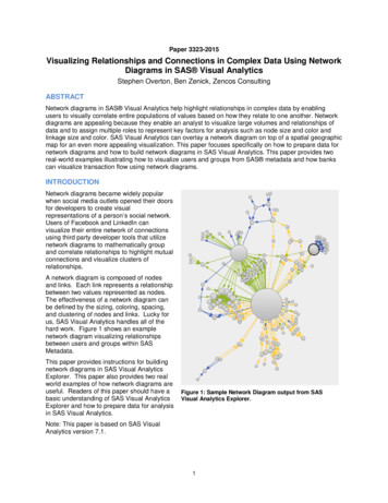
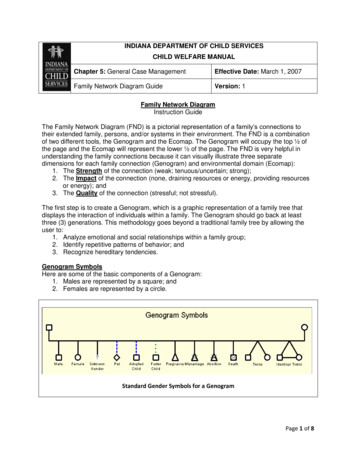
Network DiagramThe Network Diagram is intended to accurately portray the cardholder data environment and its associatedsystems and components, and clearly indicate in-scope and out-of-scope network segments.The high-level diagram must include the following:o All in-scope network segmentso All systems and components which store, process, or transmit cardholder data, including but notlimited to: Firewalls Web application servers Databases and database servers PoS terminals Payment applications Workstationso All systems and components which connect to systems which process, store or transmit cardholderdata, including, but not limited to: Admin workstations Other workstations Connected third partieso All systems and components which support the security of the CDE, including, but not limited to: Anti-virus servers Logging servers IDS/IPS systems FIM servers System administrator workstations Hardware security modules Vulnerability scanner Two-factor authentication solution Access control mechanisms Key management systemso Devices which provide connectivity and segmentation including, but not limited to: Firewalls Web application firewalls Routers Load balancers Layer-three switches VPN concentratorso All locations sampled in the report, including, but not limited to: Retail locations Datacenters Corporate locations Hosting providers Connected 3rd partieso Any wireless networks or devices, whether in scope or not. If the wireless components are not inscope they should be labeled as such.o Other systems and components as applicableo Non-PCI segments (clearly labeled as such)o All connections into and out of the network, including demarcation points between the cardholderdata environment (CDE) and other networks/zoneso Direct connections to any other entity, including card brandso A key or legend as neededo Date of last review
Additional details:o Diagram must clearly correspond to the connectivity diagram (see p. 4)o All systems included in the diagram must be clearly labeled, to include make/model and function (e.g.Win2008 e-comm web server, Cisco ASA 5510 border firewall)o Do not include IP addresses or hostnames. Only functional descriptions should be used.o All diagrams must be legible on 8.5 x 11 paper. If they cannot be easily read on the page then theyshould be split into multiple diagrams.o Where multiple devices perform the same function, e.g., clustered devices and server farms, thesecan be represented by a single objecto Virtual servers and virtual networks should be grouped inside a container which is shaded to indicatethe virtual environment
Sample Network Diagram
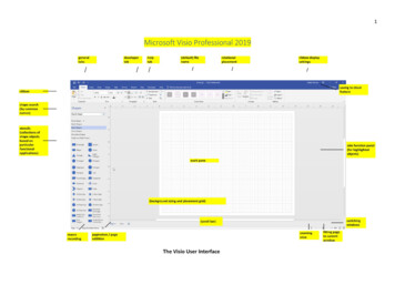
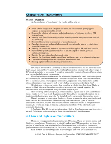
Connectivity DiagramThe connectivity diagram is intended to portray communications between the cardholder data environment andother networks. The connectivity diagram must include the following:o All external connections to third parties, including payment processors, service providers, cardbrands, etc.o All internal environment, networks, or systems which are connected to the CDEo All boundaries of the CDEo Any segmentation points used to reduce the scope of the assessmento All wireless networkso All physical locations (some locations, such as retail stores, can be depicted with single representationprovided they are configured identically)o Other connection points applicable to the assessment as neededo All locations included in the CDEo A key or legend as neededo Date of last review Additional details:o All segments must be labeled in a consistent manner which corresponds to the labeling on the highlevel diagramo All segments must indicate if they are in scope or out of scopeo All systems and components must be labeled in a consistent manner which corresponds to thelabeling on the high-level diagramo Diagram must clearly correspond to the high-level diagram (see p. 1)o For each communication point show the applicable device interfaces, network technologies,protocols, and security controls applicable
Sample Connectivity Diagram
Network Diagram. The Network Diagram is intended to accurately portray the cardholder data environment and its associated systems and components, and clearly indicate in-scope and out-of-scope network segments. The high-level diagram must include the following: o All in-scope network segments