Transcription
The Genuine. The Original.TABLE OF CONTENTSSECTIONPAGEPRE-INSTALLATION CHECKLIST . . . . . . . . . . . . . . . . . . . 2-3PARTS IDENTIFICATION . . . . . . . . . . . . . . . . . . . . . . . . . . . . . . 4-6SAFETY INFORMATION & SAFETY FEATURES . . . . . . . . . . 7OPERATOR ASSEMBLY & INSTALLATION . . . . . . . . . . . 8-16OPERATOR ASSEMBLY . . . . . . . . . . . . . . . . . . . . . . . . . . 8-11OPERATOR INSTALLATION. . . . . . . . . . . . . . . . . . . . . 12-16SAFE-T-BEAM SYSTEM INSTALLATION. . . . . . . . . . . 17-18WALL CONTROL INSTALLATION . . . . . . . . . . . . . . . . . . . . . . 19CONNECTING POWER. . . . . . . . . . . . . . . . . . . . . . . . . . . . . . . . . 20SETTINGS . . . . . . . . . . . . . . . . . . . . . . . . . . . . . . . . . . . . . . . . . 21-22FORCE ADJUSTMENT . . . . . . . . . . . . . . . . . . . . . . . . . . . . . 21LIMIT SWITCH ADJUSTMENT. . . . . . . . . . . . . . . . . . . . . . 22CONTACT REVERSE . . . . . . . . . . . . . . . . . . . . . . . . . . . . . . . 22WIRELESS CONTROLS . . . . . . . . . . . . . . . . . . . . . . . . . . . . . 23-26BATTERY / VISOR CLIP INSTALLATION . . . . . . . . . . . . . 23PROGRAMMING REMOTE CONTROLS . . . . . . . . . 23-24WIRELESS KEYPAD INSTALLATION . . . . . . . . . . . . . . . . . 24PROGRAMMING WIRELESS KEYPAD . . . . . . . . . . . 25-26OPERATING SAFETY INSTRUCTIONS . . . . . . . . . . . . . . . . . 26OPERATIONAL FEATURES . . . . . . . . . . . . . . . . . . . . . . . . . 27MAINTENANCE . . . . . . . . . . . . . . . . . . . . . . . . . . . . . . . . . . . . 27-30PERIODIC MAINTENANCE . . . . . . . . . . . . . . . . . . . . . 27-28TROUBLESHOOTING GUIDE . . . . . . . . . . . . . . . . . . . 28-29WIRING DIAGRAM . . . . . . . . . . . . . . . . . . . . . . . . . . . . . . . . 30WARRANTY . . . . . . . . . . . . . . . . . . . . . . . . . . . . . . . . . . . . . . . . . . . 30ACCESSORIES . . . . . . . . . . . . . . . . . . . . . . . . . . . . . . . . . . . . . . . . . . ASERVICE INFORMATION . . . . . . . . . . . . . . . . . . . . . . . . . . . . . . 13CompletewithRemote ControlandSERIES II ElectronicsIncluded Wall Control MUST be installed priorto Operation of this Garage Door Operator.Safe-T-Beam Safety Reverse System Mustbe Installed and the Force Controls Must beProperly Set to close door.This Equipment meets or exceeds all Federal,State and UL 325 Safety Requirements.* Will not operate twice as faston a one-piece door.NEED HELP?Please call us if you are having difficulty, for any reason.We would like to help you.Call: 1.800.929.3667Web: www.overheaddoor.com3505735581REUTFU CER ENFO ERVE EFSA R
PRE-INSTALLATION CHECK LISTFOR HELP-1.800.929.3667 OR OVERHEADDOOR.COMThings to consider if you are planning to “do-it-yourself.”2In many cases you will be replacing an existing door operator with a new one. However, ifthis will be the first operator installed there are some pre-installation issues which need tobe addressed. They are as follows:(The issue numbers below refer to the circled numbers on the illustrations which appear on page 3.)Check your ceiling where the power headof your new unit will be mounted. Plan howyou will be mounting the Power Head.It is possible that ceiling joists simply may notbe in the exact position needed with respect tothe garage door operator. In any case it maybe necessary to add an additional bracket andfasteners (not included with your new dooroperator kit).1Check the wall directly above the garagedoor. The door operator’s header bracketmust be securely fastened to this wall. Insurethat the structure will provide a strong mountinglocation. You may need to attach a board to thewall frame in this area.2Check to see if the mounting location forthe Safe-T-Beam System is clear fromobstruction and has a wood surfaceavailable for attaching the STB brackets. Thebrackets may also be attached to concrete ifnecessary but extra tools and special fasteners(not supplied) will be required.NOTE: 1-1/2" STB Adapters are availablethrough your local Genie Dealer.3Is your garage door made of light-weightsteel, aluminum, fiberglass, or glasspanels? Additional support bracing must beadded to these type doors. If this is the case,please contact the door distributor or manufacturerso that they can furnish you with a “bracing kit.”4Ensure that your door is properly balancedand moving freely. SEE WARNING BELOW.(This Operator is equipped with an AutomaticGarage Door Balance Detection System. See page28, Troubleshooting section.)7(NOT SHOWN) If your garage does not havea separate entry door. You might want toconsider a GER-2 Emergency Release Kit forinstallation on your garage door. Contact CustomerService or visit the web site for information.8WARNINGIf your door sticks, binds, or is out ofbalance, have it adjusted by a professional.Door springs, cables, pulleys, brackets andassociated hardware are under extremetension and can cause serious injury ordeath.TOOLS REQUIRED5/32"Drill BitStepladderWrenchTape MeasureHammer3/8", 7/16", 1/2"and 9/16" SocketsRatchetADDITIONAL TOOLSYou need a 110-120 Volt power supplyavailable. If you plan to plug the unit into astandard electrical outlet, is one available?The outlet should be no more than 3 feet fromthe power head once it is mounted.56Phillips ScrewdriverYOU MAY NEEDPencilPliersWire StrippersTo avoid damage to your door and/oroperator, make sure you disable any doorlocks prior to installing your operator.DrillStraight Blade ScrewdriverHack SawCarpenter’s Level
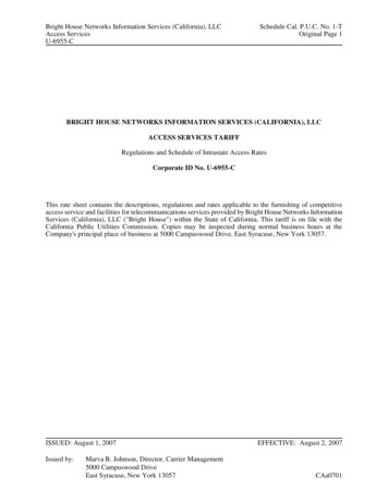
TYPICAL SECTIONAL DOOR INSTALLATION512TYPICALSUPPORTBRACKETADDEDHEADER BRACKETMOUNTING BOARD3BRACES36” POWER CORDTO120V GROUNDEDOUTLETEXTENSION SPRINGORTORSION SPRING4363SAFE-T-BEAM TYPICAL (TRACKLESS)1-PIECE DOOR INSTALLATION7TYPICAL (TRACK GUIDED)1-PIECE DOOR INSTALLATIONSECTIONAL DOORONE-PIECE DOOR
PARTS IDENTIFICATION4FOR HELP-1.800.929.3667 OR 1PQRS3690449V2539454049NUSTBSENDSENS-15250NOTE: Accessories vary by Model.FASTENERS - Shown Full Size. See Parts List for description.24732Clevis Pin1/4"-20 Shoulder Bolt85333Cotter Pin1/4"-20 Nut361/4"-20 x 5/8" Bolt21555/16"-18 x 3/4" Bolt3/8"-16 Nut38#8-32 x 1" Screw56Insulated Staple4130Rubber Bumper3/8"-16 x 7/8" Bolt5/16"-18 Nut16Wire Clip543511#10-16 x 1-1/4" Phillips Hex Head Screw#6 x 1-1/4” Pan Head Screw1/4" x 2" Lag Screw46Coupler1/4"-20 x 3/4" Self-Drilling Screw
1-PIECE BOOM HARDWARE EXPLODED VIEW“PRO” ONLY[3]5NOTE: The Operator will notfunction unless the Safe-T-Beam System is installed and theForce Controls are properly 4333622243223351533Assembly for 10' or 12' door includes:1. Special “Close” Limit Switch with longerwires.2. 96" Emergency Release Cord (yellow)3. Rail Support Kit
PARTS LISTPOWER HEAD EXPLODED VIEW[1]6Item Part 3839404142434445464748495051525354555657Power Head Assembly (main carton)1/4"-20 Hex Head Shoulder Bolt (blue bag)Boom Assembly (1 piece)(packaged separately)1/4"-20 Hex Serrated Flange Nut (blue bag)5/16"-18 Hex Serrated Flange Nut (blue & orange bag)Carriage Assembly (main carton)Boom Strap (blue bag)1/4"-20 Hex Head Bolt (blue bag)Open Limit Switch Assembly (White)(green bag)Close Limit Switch Assembly (Brown) (green bag)No. 8-32 x 1" Hex Head Screw (green bag)Emergency Release Cord (green bag)Emergency Release Cord (long)(yellow)Emergency Release Knob (green bag)Emergency Release Tag (green bag)Header Bracket (orange bag)Door Bracket (orange bag)1/4" x 2" Lag Screw (orange bag)Straight Door Arm (main carton)Clevis Pin (yellow bag)Cotter Pin (yellow bag)Curved Door Arm (main carton)3/8" x 7/8" Hex Head Bolt (yellow bag)3/8" Hex Serrated Flange Nut (yellow bag)Wire (main carton)Insulated Staple (red bag)Wall Button (red bag)Wall Console (main carton)#6 x 1-1/4" Pan Head Screw (red bag)Entrapment WARNING Label (manual)Safe-T-Beam (STB) Sensor (Green LED)(main carton)Safe-T-Beam (STB) Source (Red LED)(main carton)Safe-T-Beam (STB) Bracket (yellow bag)Coupler (blue bag)No.10-16 x11/4" Phillips Hex Head Screw (yellow bag)Single Button Remote Control (main carton)Multi-Button Remote Control (main carton)Wireless Keypad (main carton)2-Button Remote Control (main carton)Safety & Maintenance Guide (manual)Wire Clip (green bag)Carriage Stop (blue bag)5/16"-18 x 3/4" Hex Head Bolt (orange bag)1/4-20 x 3/4" Self-drilling Screw (orange bag)Mounting Straps (main carton)1AParts ' & 12' only11111KSERIAL NUMBER1Dvaries/model122122 95ft s/modelvaries/modelvaries/modelvaries/model1POWER HEAD PARTS LISTvaries/model1Item Part 1L1M1N1PPower Head AssemblyLens (By Series/Model)Top Plate AssemblyLight Socket (2)Motor AssemblyCoverOpto WheelMotor Drive BoardController BoardNo. 10-24 x 3/8” Hex HeadNo. 8-32 x 1” Phillips ScrewNo. 8-32 x 3/8” Slotted Hex Head ScrewToroidPower Cord
SAFETY INFORMATIONOPERATOR INSTALLATIONOVERVIEW OFPOTENTIAL HAZARDSGarage Doors are large, heavy objects that move with the help of springsunder high tension and electric motors. Since moving objects, springs undertension, and electric motors can cause injuries, your safety and the safety ofothers depend on you reading the information in this manual. If you havequestions or do not understand the information presented, call your nearestservice representative.In this Section and those that follow, the words Danger, Warning, andCaution are used to emphasize important safety information. The word:DANGER means that severe injury or death will result from failure tofollow instructions.WARNING means that severe injury or death can result from failure tofollow instructions.CAUTION means that property damage or injury can result from failure tofollow instructions.The word NOTE is used to indicate important steps to be followed orimportant SHOCKHIGHSPRINGTENSIONEFFECTWARNING:Can CauseSerious Injuryor DeathWARNING:Can CauseSerious Injuryor DeathPREVENTIONKeep people clear of opening while door ismoving.Do Not allow children to play with the dooroperator.Do Not operate a door that jams or one thathas a broken spring.Turn off power before removing operatorcover.When replacing cover, make sure wires arenot pinched or near moving parts.Operator must be properly grounded.Do Not try to remove, repair or adjustsprings or anything to which door springWARNING: parts are fastened, such as, wood blocks,Can Cause steel brackets, cables or other like items.Serious Injury Repairs and adjustments must be made byor Deatha trained service person using proper toolsand INGWARNING::To reduce the risk ofsevere injury or death:1. READ AND FOLLOW ALL SAFETY, INSTALLATION ANDOPERATION INSTRUCTIONS. If you have any questions ordo not understand an instruction, call your servicerepresentative.2. Do Not install operator on an improperly balanced door. Animproperly balanced door could cause severe injury. Repairsand adjustments to cables, spring assembly, and otherhardware must be made by a trained service person usingproper tools and instructions.3. Remove all ropes, and disable all locks connected to thedoor before installing operator.4. Install door operator 7 feet or more above the floor. Mountthe emergency release knob 6 feet above the floor.5. Do Not connect the operator to the source of power untilinstructed to do so.6. Locate the control button: Within sight of door. At a minimum height of 5 feet, so small children cannotreach it. Away from all moving parts of the door.7. Install the entrapment WARNING label next to the wallbutton or console. Install the emergency release tag on, ornext to, the emergency release8. The operator must reverse when the door contacts a 1-1/2inch high object on the floor at the center of the doorway.This is about the size of a 2" x 4" board laid flat.SAFETY FEATURES (varies by model )Safe-T-Beam (STB) Non-Contact Reversing SystemPlaces an invisible beam across door opening, that reverses the door during down travel to the fully openposition if anything passes through beam.Safe-T-Reverse Contact Reversing SystemAutomatically stops and reverses a closing door within 2 seconds of contact with an object.Safe-T-Stop Timed Reversed SystemAutomatically opens a closing door, if door does not close within 30 seconds.Force Guard ControlUsed to set the force required for opening and closing door. For maximum safety, set the minimum forcerequired to fully open and close door.Automatic Lighting SystemTwo light bulbs up to 60 Watts max. each, are used for safer entries and exits. The light turns on when door isactivated and automatically turns off 4.5 minutes later.Manual Emergency ReleaseAllows the garage door to be opened or closed manually for emergencies or maintenance.7
1.OPERATOR ASSEMBLY & INSTALLATIONFOR HELP-1.800.929.3667 OR OVERHEADDOOR.COMRecord your Model Number and SerialNumber now on page 11 in the center ofthis manual.8OPERATOR ASSEMBLYOPEN BLUE PARTS BAGNOTE: 3 piece operator assembly is for doors upto 7 feet 6 inches high. An extension kit for an 8 feethigh door is available.CouplerAssemble on a clean, flat surface.Fig. 1-1 Install rubber bumper and coupler1. Install coupler [46] (Fig. 1-1). Line up and slide on motor shaft.CAUTIONDrive screw and boom liner can slide outof boom sections. Keep boom sectionslevel until operator is fully assembled.2. Connect boom to power head. Either 1-pieceboom or first section of 3-piece boom(Fig. 1-2). Insure arrow on boom points away from powerhead. (Fig 1-4 on page 9.) Push drive screw out about 5 inches. Line up and slide drive screw into coupler. Slide boom into bracket and line up holes withthose on power head (Fig. 1-3).– Connect with bolts [2] and nuts [8].Fig. 1-2 Push drive screw out8[2]1/4"-20 Hex Head Bolt[8]1/4"-20 Hex Flange NutFig. 1-3 Attach boom2
CAUTIONDrive screw section and boom liner can slideout of boom sections. Keep boom sectionslevel until operator is fully assembled93. On 1 piece boom assembly go to step 11.4. Arrange arrows on boom sections (Fig. 1-4). Point arrows in same direction away frompower head.5. Attach middle boom section to firstboom section. Push middle drive screw out about 2 inchestoward the power head. Slide collar [13] over the middle boom hook(Fig. 1-5). Turn screw by hand to align coupler hooksbetween first and middle boom sections. Latch the two hooks together andslide the collar over them (Fig. 1-6). Snap clip [14] next to collar (Fig. 1-7).6. Attach boom clamps at the middle boom tofirst boom joint (Fig. 1-8). Slide the middle boom section against the firstboom section. Place a boom clamp on each side of the boomat the joint and line up the holes with those inthe boom. Finger tighten boom clamps with bolts [10] andnuts [11].Fig. 1-4 Arrange arrowsslide collarFig. 1-5slide collarFig. 1-67. Attach end boom section to middle boomsection to first boom section (Step 6).8. Attach boom clamps at the end boom tomiddle boom joint (Fig. 1-8). Repeat procedure used to attach middle boomsection to first boom section (Step 7).NOTE: If installing a 3-piece boom assembly onan eight foot high door refer to the instructionsheet included with the optional boom extensionat this point.11Collar[11]5/16"-18 Hex Head Flange NutFig. 1-7[13][10]5/16"-18 Hex Head Shoulder Boltclip[14]Retaining ClipClamphet10Fig. 1-8 Attach rail clamps
109. Install carriage and carriage stop (Fig. 1-9). Slide carriage stop into railand along the lengthof the rail to the power head. Point arrow on side of carriage toward door. Place carriage lever in release position. Slide into carriage slot of boom assembly.NOTE: Carriage release lever will be facingpower head.10. Attach boom strap (Fig. 1-10). Connect to end boom section with bolts[16] and nuts [8].EngagedpositionFig. 1-9 Install carriage[8][16]1/4"-20 Hex Head BoltRelease position1/4"-20 Serrated Hex NutFig. 1-10 Attach boom strap11. Tighten all nuts and bolts.NOTE: Tighten nuts and bolts on boom so thatthey grip metal snuggly. Do Not Over-Tighten.Hinge tabs12. Install lens cover (Fig. 1-11). Align hinge tabs with slots on motor cover(Fig. 11A). Move antenna outside lens and out of way. Push hinges into slots on cover untilthey snap into place (Fig. 11B). Swing lens cover closed and snap into place.SlotsFig. 1-11A Install lensPush in until they catchOPEN GREEN PARTS BAG13. Place limit switches (Fig. 1-12). Turn unit right side up. Uncoil limit switch wires. Place switches on boom with arrows pointingtoward boom strap.– Place CLOSE limit switch (brown wire) 12"from boom strap.– Finger tighten the hold-down screw [21].– Lay out the wire in the channel on top of theboom, using wire clips [53] to hold it in placeas you go toward the power head.– Save one clip for the OPEN switch.– Place OPEN limit switch (white wire) 12"from power head. (Place over brown wire.)– Finger tighten the hold-down screw.– Lay out the wire in the channel on top of theboom, using the last wire clip to hold bothlimit switch wires in place.NOTE: Do not over-tighten screw [21] on limitswitch brackets. Limit switch adjustments will be made later.Fig. 1-11B Install lensCLOSE21Arrow points toward boom strapOPENLast wire clip [53]power headFig. 1-12 Limit switch placement
14. Bundle excess limit switch wires (Fig. 1-13). Leave just enough wire to easily reachthe terminals on back of power head. Hold the ends of the wires out beyond the backof the power head as you flip the unitupside-down again.11LIMIT SWITCH WIRING CONNECTIONSNOTE: Loosen (Do Not Remove) screwsfrom terminals.Fig. 1-13 Bundle excess wire15. Connecting limit switch wires to terminals(Fig. 1-14). Connect one “OPEN” limit switch (white) wire toterminal 4. Connect the other “OPEN” limit switch (white)wire and one “CLOSE” limit switch (brown) wireto terminal 5. Connect the other “CLOSE” limit switch (brown)wire to terminal 6.Antenna16. Attach emergency release knob and cord(Fig. 1-15). Tie overhand knot at one end of cord. Thread opposite end of cord through knob andhole in carriage lever. Tie overhand knot at this end of cord.Fig. 1-14 Limit switch terminal connections17. Attach emergency release tag (Fig. 1-16). Thread wire through small hole incarriage lever. Wrap wire around itself, tie tight.NOTE: If your garage is equipped with only oneentrance — please consider installing an optionalEmergency Release Kit. See page B.Fig. 1-15 Attach emergency release knob/cordIf you have not yet recorded the model and serialnumbers, do it now prior to installation.FILL THIS IN AT TIME OF INSTALLATION FOR YOUR OWNRECORDS,SO THAT IT WILL BE AVAILABLEIF YOU EVER NEED TO CALL US.Date Purchased / /Serial Number(see pg. 6 for location)Operator ModelRemote Control Model(see page 23 for location)Dealer NameFig. 1-16 Attach emergency release tag
OPERATOR INSTALLATIONTRACK GUIDEDWHAT TYPE OF DOOR DO YOU HAVE?12Look at the photos on the right. Door type determineswhich of the remaining installation steps apply to you.TrackNOTE: Will Not Operate twice as fast on a one-piecedoor.1. Determine type of garage door (Fig. 1-17).Type OneTrack-guided doors–May be sectional orone-piece (rare) with wheels attached whichride within a metal “track.”Type TwoTrackless–One piece doors only, normallyuses a system of very heavy framework forbracing, and has no “track” but swings onlarge spring loaded hinges or pivots ateither side of the door.TRACKLESSFig. 1-17 Type of doorCenterline (“C”)FOR TRACK GUIDED DOORS2. Find center of door and header* (Fig. 1-18). Close door. Measure door width.– Mark a vertical line (“C”) in the center oninside of door and header.3. Find header bracket position. Raise door, watching top edge of door. Stop door when edge reaches highest pointof travel. Measure distance from top edge of door tofloor (distance “H”) (Fig.1-19).– add 2-1/2 inches to “H” (Fig. 20). Draw horizontal line across line “C” atthis height on header.Fig. 1-18 Find center of doorTrack guided doorsHIGHEST POINT OFTRAVELHIGHEST POINT OFTRAVELTrackHeader“H”“H”SectionalNOTE: If spring is in the way, place headerbracket above spring. Do Not Move Door Spring.One-pieceFig. 1-19 Find distance “H”Header bracketgoes here* The header is a heavily reinforced section of thewall just above the top of the garage dooropening. Usually consisting of an engineeredlumber beam or layers of 2" x 12" lumber andparticle board sandwiched together.Highest point of travel 2 1/2"(horizontal line)Top of doorCenterline (“C”)Fig. 1-20 Find header bracket position
FOR TRACKLESS DOORS2. Find center of door and header (Fig. 1-21). Close door. Measure door width.– Mark a vertical line (“C”) in the center onthe inside door and header.3. Find header bracket position. Raise door, watching top edge of door. Stop door when edge reaches highest pointof travel. Measure distance from top edge of door tofloor (distance “H”) (Fig.1-22).– Add 6 inches to distance “H” (Fig.1-23). Draw horizontal line across line “C” at this heighton header.Centerline (“C”)13Fig. 1-21 Find center of doorTrackless DoorsHIGHEST POINT OF TRAVELNOTE: Operator Will Not Operate twice as fast on aone-piece door.“H”“H”CAUTIONHeader bracket must be fastened to garageframing. Do Not fasten to drywall, particle board,plaster or other such material.Fig. 1-22 Find distance “H”It may be necessary to attach a board across thewall studs above the door header, to serve as amounting plate for the header bracket, so thebracket can be mounted at the proper locationand have sufficient support.OPEN ORANGE PARTS BAGHighest point of travel 6"(horizontal line)Centerline (“C”)4. Mount header bracket. Set flange (where boom strap attaches to bracket)on your vertical line (Fig. 1-23). Set bottom of bracket on your horizontal line.(Fig. 1-24). Mark 2 hole positions. Drill two 5/32 inch holes. Attach bracket with 2 lag screws [30].Top of doorFig. 1-23 Find header bracket position[30]Lag ScrewFig. 1-24 Header bracket orientation
5. Attach boom at header bracket (Fig. 1-25). Place threaded end of boom strap through holeon header bracket. Finger tighten nut [11] on threads.142611[11]5/16"-18 Flange NutFig. 1-25 finger tight6. Find power head position. Raise power head and temporarily supportabove door. (Use step ladder, etc.) Open door until the top edge reaches thehighest point of travel. Center boom above door.Track guided doorsHIGHEST POINT OFTRAVELHIGHEST POINT OFTRAVELFOR TRACK GUIDED DOORS– Raise power head until boom is level or slightlybelow (Fig. 1-26). Temporarily support power head.TrackTrackSectionalOne-pieceFig.1-26 Find power headpositionTrackless DoorsFOR TRACKLESS DOORS– Raise power head until boom is 1 to 1-1/2inches above door (Fig. 1-27). Temporarily support power head.CAUTIONHIGHEST POINT OF TRAVEL1"-1 1/2"1"-1 1/2"Fig. 1-27 Find power head positionMounting brackets must be fastened to garageframing. Do Not fasten to drywall, particle board,plaster or other such materials.7. Mount power head (Fig. 1-29 next page).8. Close door.9. Tighten boom strap nut [11] at header bracket(Fig. 1-28).10. Install door brace if needed (See caution onnext page).Fig. 1-28FOR HELP-1.800.929.3667 OR OVERHEADDOOR.COM
FOR HELP-1.800.929.3667 OR OVERHEADDOOR.COMFig. 1-29 Mounting MethodsOPEN BEAM CEILINGPerforated Angle IronMounting Straps[30][30][11][55]NOTE: Materials may vary.NOTE: Read all instructions completely.Garage constructions differ, so it may berequired to supply extra material andmodify instructions.10. Install door brace if needed (See caution below).CAUTIONDoors made of masonite, lightweight wood, fiberglass,and metal must be properly braced before mountingdoor operator.15[11][55]FINISHED CEILINGLocate the ceiling joists ortrusses using a stud finderor similar device.Attach angle iron(not included onall models) to joiststhrough thefinish materialusing lag[30]screws (30).SECTIONAL Doors“C”Top of doorNOTE: PRIOR TO PROCEEDING WITH STEP 11 —CONTACT DOOR DISTRIBUTOR FOR INSTRUCTION / ASSISTANCE ON INSTALLING THE DOOR BRACKETFOR SECTIONAL DOORS11. Install door bracket (Fig. 1-30A). Contact door distributor. Locate on centerline, no lower than top rollers(Fig. 1-30B). Attach using self-drilling screws [56] formetal doors, orUse lag screws [30] for wooden doors. (Checklength of screws vs thickness of door prior touse. Your door may require shorter screws.)FOR 1-PIECE DOORS11A. Install door bracket (Fig. 1-31). Contact door distributor. Mount on centerline as high on the dooras possible. Attach using self-drilling screws [56] formetal doors, orUse lag screws [30] for wooden doors. (Checklength of screws vs thickness of door prior touse. Your door may require shorter screws.)Even with or above top roller. See Fig. 1-31Fig. 1-30A Install Door Bracketeven with orabove top rollerFig. 1-30B Install Door BracketONE-PIECE Doors“C”Attach at highestpossible point on door.“C”Top of doorTop of door[56]1/4"-20 x 3/4" Self-Drilling Screw“C”[30]Fig. 1-31 Install Door Bracket1/4" x 2" Lag Screw“C”
2.SAFE-T-BEAM SYSTEM INSTALLATIONFOR HELP-1.800.929.3667 OR OVERHEADDOOR.COMWARNING16There should be no electrical power to the operatorwhile installing Safe-T-Beam System wires. If youhave plugged in the power cord–UNPLUG IT NOW.NOTE: Operator will not close door automaticallyunless the Safe-T-Beam System is installed.1. Mounting brackets. Mark both sides of garage door frame or wall 5"above floor. (Fig. 2-1). Hold bracket against door frame or wall.– Check if brackets extend out from wall farenough, so tongue of bracket is beyond door,tracks or any door hardware.– If not:a. “STB” bracket extensions are availableat local dealer.b. Blocks of wood, etc. may be substitutedfor extensions. Center bracket on your mark (Fig. 2-2). Fasten each with 2 screws (47) (Fig. 2-2).[47]#10-16 x 1-1/4"markFIG. 2-1 Mark door framecenter ofbrackettongueFIG. 2-2 MountbracketsNOTE: Mounting brackets can be attached tobrick walls or concrete floor using masonryanchors (not provided).2. Mounting “STB” source and sensor. If garage has only one garage door.– Determine which side of garage receivesmost direct sunlight (Fig. 2-4), and place RedLED here whenever possible (Fig. 2-4). For multiple doors.– Preventing crossed signals is critical.– Place source and sensor modules onadjacentdoors facing in opposite directions (Fig. 2-4).NOTE: To help prevent interference from sun, “STB”sensors (Green LED) may be placed further from the dooropening where they will spend more time in shadows. Slide source/sensor onto tongue of bracket untilit clicks into place (Fig. 2-3).FIG. 2-3 AttachingSTB’s to bracketsSUNREDLEDGREENLEDRED REDLED LEDGREENLEDTWO DOORGARAGEONE DOORGARAGEGREENLEDGREENLEDRED REDLED LEDGREEN GREENLEDLEDREDLEDTHREE DOORGARAGEFIG. 2-4 STB locationsOPEN RED PARTS BAGDashed Line striped wireSolid Line white wire3. Wiring. Route wire (37) using either method shown(Fig. 2-5). Wires between power head and garage doorwall should be run along top of boom.– Use wire clips to hold them in place.[53]– Wires can be slipped under the wireclips already in eadAGreenSensorBFIG. 2-5 STB wiring methods
OPEN YELLOW PARTS BAGSECTIONAL12. Install door arms (Fig. 1-32).FOR SECTIONAL DOORS32 33– Attach straight arm to carriage.– Secure with clevis [32] and cotter pin [33].– Attach curved arm to door bracket.– Secure with clevis [32] and cotter pin [33].As short aspossible35 3632 33Curved endtowarddoorFOR 1-PIECE DOORS– Attach curved arm to carriage.– Secure with clevis [32] and cotter pin [33].– Attach straight arm to door bracket.– Secure with clevis [32] and cotter pin [33].13. Close door completely. Make sure emergency release is disengaged.Fig. 1-32 Join door arms (track-14. Join door arms (Fig.1-33). Overlap door arms.1-PIECENOTE: For sectional doors overlap arms as muchas possible. Make arm assembly as long aspossible for one piece doors. Move carriage as necessary to align holes.– Secure with bolts [35] and nuts [36].[35][36]32 33Curved endtowardcarriage3/8"-16 BoltAs long aspossible32 3335 363/8"-16 NutFig. 1-33 Join door arms (track-15. Adjust emergency release cord . Pull cord through carriage lever until knob is6 feet above floor. Tie new overhand knot in cord at carriage lever. Cut excess cord. Check all hardware for tightness.16.Install light bulbs (not provided)(Fig. 1-34). Remove power from operator (if required). Lower lens cover.– Push in lens latches and pull down on frontof lens cover. Do Not use short neck bulbs. Use bulbs rated for:– 60 Watts Maximum.– Rough service recommend. Screw bulbs into light sockets.60 WATTS MAXIMUMNOTE: Do Not overtighten light bulbs in sockets.NOTE: Use of 130 Volt lights is recommended forlonger bulb life.Fig. 1-34 Install lightLENS LATCHES —PUSH IN TO RELEASE17
3. Wiring (cont’). Securely fasten wires to wall as you go.– Use insulated staples (included).18 1/2"[38]– Staples should be snug only. 1-1/4" to 1-1/2"FIG. 2-6 Splitting and strippingCAUTIONStaples which are too tight can cut or pinch wires. Cutor pinched wires can cause the “STB” System to stopworking. When using the insulated staples, make sureyou fasten them only as tightly as needed to hold the Make wire attachments at “STBs.”– Split and strip wire ends to be connectedas shown (Fig. 2-6).– Loosen terminal screws.– Insert wire under flat plate and tighten screw.It does not matter which wire, white orstriped, goes on which terminal (Fig. 2-7). Make wire attachments at power head.– “STBs” are connected to terminals #2 and #3on power head (Fig. 2-8). It does not matterwhich wire, white or striped, goes onwhich terminal.4. Check the following. Insure that no part of door or its hardware isin path between lenses of source and sensor. Insure that tops of lenses a
the garage door operator. In any case it may be necessary to add an additional bracket and fasteners (not included with your new door operator kit). 2Check the wall directly above the garage door. The door operator's header bracket must be securely fastened to this wall. Insure that the structure will provide a strong mounting location.