Transcription
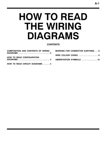
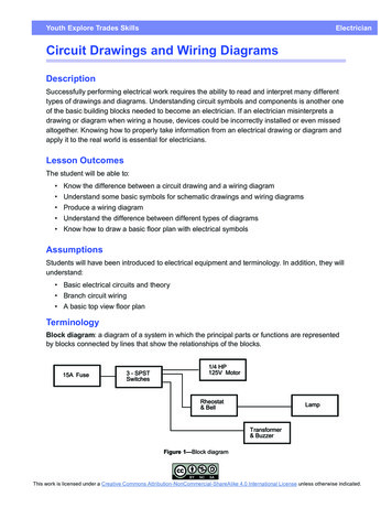
Youth Explore Trades SkillsElectricianCircuit Drawings and Wiring DiagramsDescriptionSuccessfully performing electrical work requires the ability to read and interpret many differenttypes of drawings and diagrams. Understanding circuit symbols and components is another oneof the basic building blocks needed to become an electrician. If an electrician misinterprets adrawing or diagram when wiring a house, devices could be incorrectly installed or even missedaltogether. Knowing how to properly take information from an electrical drawing or diagram andapply it to the real world is essential for electricians.Lesson OutcomesThe student will be able to: Know the difference between a circuit drawing and a wiring diagram Understand some basic symbols for schematic drawings and wiring diagrams Produce a wiring diagram Understand the difference between different types of diagrams Know how to draw a basic floor plan with electrical symbolsAssumptionsStudents will have been introduced to electrical equipment and terminology. In addition, they willunderstand: Basic electrical circuits and theory Branch circuit wiring A basic top view floor planTerminologyBlock diagram: a diagram of a system in which the principal parts or functions are representedby blocks connected by lines that show the relationships of the blocks.Figure 1—Block diagramThis work is licensed under a Creative Commons Attribution-NonCommercial-ShareAlike 4.0 International License unless otherwise indicated.
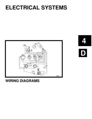
Circuit Drawings and Wiring DiagramsElectricianCircuit drawing (diagram): a simplified conventional graphical representation of an electricalcircuit.10'SYMBOL LEGEND21 mmDuplex receptacleSingle-pole switch1 4 fluorescentlight fixture21 mmElectricalpanelEMT runArmoured cablerun (B/X)12'4x4 junction boxFigure 2—Circuit drawingLine diagram: a one-line diagram or single-line diagram is a simplified notation for representingan electrical system. The one-line diagram is similar to a block diagram except that electricalelements such as switches, circuit breakers, transformers, and capacitors are shown bystandardized schematic symbols.Figure 3—One-line diagram2Youth Explore Trades Skills
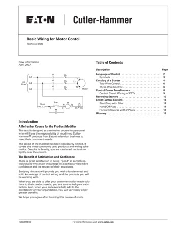
ElectricianCircuit Drawings and Wiring DiagramsPictorial diagram: a diagram that represents the elements of a system using abstract, graphicdrawings or realistic pictures.Schematic diagram: a diagram that uses lines to represent the wires and symbols to representcomponents. It is used to show how the circuit functions.Figure 4—Schematic diagramWiring diagram (or pictorial): a simplified conventional pictorial representation of an electricalcircuit. It shows the components of the circuit as simplified shapes, and how to make theconnections between the devices. A wiring diagram usually gives more information about therelative position and arrangement of devices and terminals on the devices.Figure 5—Wiring diagramYouth Explore Trades Skills3
Circuit Drawings and Wiring DiagramsElectricianEstimated Time2–3 hoursRecommended Number of Students20, based on BC Technology Educators' Best Practice GuideFacilitiesClassroom, or technology education shopToolsPencils, rulers, erasersMaterialsBlank paper, photocopies of standard floor plansOptionalDrafting table, T square, 90 triangleResourcesAttached drawing and wiring diagram4Youth Explore Trades Skills
ElectricianCircuit Drawings and Wiring DiagramsActivity 1: Drawing Circuits1. Using the basic electrical floor plan and the symbol chart on the following pages, explainthe electrical symbols to the students.2. Give students a standard photocopy of a floor plan (see the end of this Activity Plan) thatincludes a kitchen and have them draw one or two 12-device circuits using electricalsymbols and paths for circuits as shown in the floor plan drawing (Figure 5).Note: Page 59 in the Electrical Code Simplified Book will help students to understand howmany devices are permitted per circuit and their electrical symbols.3. Have students draw two outlets that require separate circuits for a fridge and a dishwasherthat go directly back to panel (homerun shown as a short line directed toward the panelwith an arrow on it).4. Have students draw a legend of symbols for their drawing.Youth Explore Trades Skills5
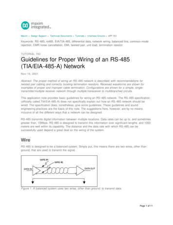
Circuit Drawings and Wiring DiagramsElectricianThe light fixtures in thehall are controlled bythese switches. Thesmall number “3”beside the switchsymbol indicates athree-way switch,which means that thehallway lights can becontrolled from twodifferent locations.This symbol, the circlewith four linesprotruding from eachpole, is usually used torepresent a ceilingmounted incandescentfixture. The note“A13” indicates thefixture is supplied bypanel A, circuit breakernumber 13.A split-switched duplexreceptacle is to beinstalled at this location.The symbol for thereceptacle includes acircle that is partlyshaded. This indicateshalf of the receptacle iscontrolled by a wallswitch. The symbol forthe switch looks like adollar sign and isconnected to thereceptacle with a line.Figure 6—Floor plan of a typical suite showing power and lighting details6Youth Explore Trades Skills
ElectricianCircuit Drawings and Wiring Diagrams-Figure 7—Common electrical symbolsYouth Explore Trades Skills7
Circuit Drawings and Wiring DiagramsElectricianActivity 2: Basic Wiring Diagram Have students produce a basic wiring diagram. The wiring diagram will show the circuit students will wire in Wiring Devices and Wiring aWall Section. The diagram should show incoming power feeding a receptacle. From the receptacle the cable feeds a switch. From the switch the cable feeds a light.Figure 8—Basic Wiring Diagram8Youth Explore Trades Skills
ElectricianCircuit Drawings and Wiring DiagramsWire one duplex outlet and one switch controlling one light,fed from the outlet.Youth Explore Trades Skills9
Circuit Drawings and Wiring DiagramsElectricianEvaluation GuidelinesThe student: Understands basic types of electrical drawings Can produce a floor plan that displays understanding Knows the difference between a circuit drawing and a wiring diagram Draws and understands a wiring diagramExtension ActivityDraw more wiring diagrams that include more devices in different configurations.Example: Wiring from a switch box running two lights. The circuit could be more complicated ifthe student understands the concepts.10Youth Explore Trades Skills
ElectricianCircuit Drawings and Wiring DiagramsPlan for Main Floor of HouseBACKPORCHBEDROOM 1KITCHEN BEDROOM 2LAUNDRYDINING ROOMBATHHALLLIVING ROOMFRONTPORCHYouth Explore Trades Skills11
Electrician Circuit Drawings and Wiring Diagrams Youth Explore Trades Skills 3 Pictorial diagram: a diagram that represents the elements of a system using abstract, graphic drawings or realistic pictures. Schematic diagram: a diagram that uses lines to