Transcription
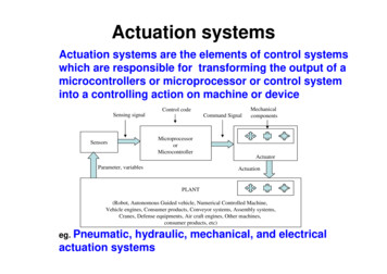
Actuation of Electro-Pneumatic System using MATLAB Simulinkand Arduino Controller- A case of a Mechatronics systems LabP. Parikh1*, R. Vasani2, S. Sheth3, J. Gohil41Assiatant Professor, 2Director, SAL College of Engineering, Ahmedabad, Gujarat, IndiaAssociate Professor, 4PG Student, G.H. Patel College of Engg. & Tech., Vallabh Vidhyanagar, Aanand, ics is an immerging branch in the present era which deals with mechanical systems,instrumentations and electronic systems. Hydraulic and Pneumatic systems are the vital elements ofMechatronics system. The actuation of hydraulic and pneumatic system can be done using a PLC or amicrocontroller. The programming could be done in a ladder language, Functional block diagram or inembedded C. This paper shows the methodology for interfacing the MATLAB simulink with pneumatic systemvia microcontroller without any burden of programming. To fulfil this purpose, MATHWORKS has designedArduino I/O packages, to communicate with Arduino controller without any programming language. The systemconsists of a relay unit, Arduino Microcontroller, Arduino IDE software, MATLAB simulink (Version 2012 orbeyond) SMPS, Direction controlled solenoid operated valve, Double acting pneumatic cylinder and a USBcable. In a nut shell this methodology will not only decrease the load of programming but also will increase theinterest of students towards Mechatronics and automation.Keywords:Arduino controller, MATLAB Simulink, Electro-Pneumatic Mechatronics system, Serial Communication1 IntroductionNickel based alloys finds wide applications in different parts of gas turbines of aircraft, steam turbine powerplants, reciprocating engines, tool & die industry, medical field, heat treatment equipments, nuclear powerplants, chemical industries, pollution control apparatus and in coal gasification and liquefaction systems. Asnickel based super alloys possesses high hardness, high strength at elevated temperature, low thermal diffusivityand high chemical reactivity with the tool materials, they are very difficult to machine conventionally. Thisleads to nick wear of the tool nose, abrasive wear of the tool, greater diffusion wear rate, fragmentation of thetool rake face, degradation of tool material by seizure and cratering, increase in the temperature of tool tip anduneven temperature distribution in the cutting tool. [1,2]. Wire electrical discharge machining (WEDM) is oneof the significant non-conventional thermoelectric process for machining of materials with high hardness,chemically reactive and which are difficult to machine using conventional methods. In WEDM material removaltakes place due to melting and evaporation by thermal energy produced due to continuous discrete sparks. Itfinds major applications in aerospace, nuclear and automotive industries to cut intricate shapes in electricallyconductive materials. Liao and Chen [3] used DEAR method for multi-objective optimization and found that theproposed method eliminates uncertainty and complication associated with PCA and Taguchi method. Sahu et.al.[4] carried out experiments on AISI D2 steel with response surface methodology to find out the effect ofmachining parameters on MRR, TWR, surface roughness and circularity. Data envelopment analysis wasapplied to find out optimal responses. Chalisgaonkar and Kumar [5] applied utility concept approach todetermine optimal combination of parameters while WEDM of pure titanium. Rajyalashmi and Ramaiah [6]used grey relational analysis to carry out multi-response optimization of WEDM parameters while machiningInconel-825. Reddy et. al. [7] applied Taguchi based DEAR method to optimize the process parameters ofEDM.This paper reports multi-quality characteristic optimization of control factors while wire electrical dischargemachining of Inconel-625 using Taguchi method integrated with data envelopment analysis based rankingmethod (DEAR). Taguchi’s L27 orthogonal array was applied for experimental design. ANOVA was performedto find out the major significant factor which affects the quality characteristics.B. Iyer, S. Nalbalwar and R. Pawade (Eds.)ICCASP/ICMMD-2016. Advances in Intelligent Systems Research.Vol. 137, Pp. 59-64. 2017. The authors - Published by Atlantis PressThis is an open access article under the CC BY-NC license (http://creativecommons.org/licens)es/by-nc/4.0/).
Parikh et al.60Fig. 1. Block Diagram of the systemFig. 2. Self Designed Pneumatic Trainer1.1 Block diagram and explanation of the systemFig 1 shows the block diagram of the system and figure 2 shows the actual self designed pneumatic trainer.Focusing on the block diagram, first MATLAB Simulink toolbox is connected with Arduino microcontrollerusing serial communication. MATHWORKS has designed Arduino I/O package to communicate with Arduinowithout any programming (As discussed in the introduction part) [1]. Blocks are set into the simulink to achievea particular PSD (position step diagram) in the electro-pneumatic system. MATLAB communicated withArduino, Arduino takes decision according to the signal feed by MATLAB and then finally triggers relays basedon the logic. Relays are supposed trigger the solenoid valves, which allows passing compressed air into thepneumatic actuators [6].Before starting the system, one needs to make sure whether MATLAB is properly connected with Arduino ornot. Once it is connected successfully, a MATLAB supporting code is to be fed in Arduino’s flash Memory [9].After completion of both the tasks, a communication port is to be selected in MATLAB simulink.Communication port is a road on which data flows between Arduino and MATLAB. Arduino is connected withMATLAB using a USB cable (9600 baud rate, 8 bits) [7].As far as the hardware is concerned, Arduino should be connected with Relay card in the TTL mode. Relayshould be connected to Solenoid valves according to the logic (NO or NC). Valves should be connected to thecylinders according to the pneumatic circuit diagram [8].1.2 Objectives and Goals of the project To get rid of ProgrammingTo have a alternate of PLCTo make system user friendlyTo acquire Live Data coming from the sensorsTo design a combination of HMI and Data AcquisitionTo make system cost effectiveTo reduce wiringTo interface sensors and wireless unit without having any responsibility of coding.To help Mechatronics, instrumentation, mechanical and electrical students who are not much familiarwith programming.1.3 Applications Paper & printing IndustriesPharmaceuticals industriesAutomation and RoboticsAs a educational Trainer for students and faculties
Actuation of Pneumatic Systems using MATLAB Simulink61 Space and Radar Applications1.4 Project flow Simulation is to be done in Automatic Studio for Electro-Pneumatic circuitElectronic circuit could be designed and simulate in ProteusBlock logic could be developed in MATLAB SimulinkArduino controller should be properly connected with MATLAB simulinkRelay unit should be connected with ArduinoSolenoid Valves should be properly connected with Relay unitFRL unit, compressor, pressure gauge and pneumatic actuators should be connected according to therequirements2 Hardware and software used in the systemTable 1 gives the information about the hardware used in the system and software details are provided in thetable 2.Sr. NoTable 1 Hardware used in the systemName of the HardwareQuantitySpecifications1Arduino Controller114 Digital I/O6 Analog I/O32 Kb Flash Memory and aserial port2Relay Unit (3 channel)1 12 Volts, 10 Amp currentcapacity, 1 NO and NCcontact3Pneumatic Actuator3Double Acting Actuators, 5”stroke and 1” bore4Solenoid Valve35/2 DCV, single sidesolenoid and Spring return( 12 volts and 150 mA)5Compressor16 bar working pressure, 1phase 230 volts 10 AmpRole in theProjectWorks as acontroller in thesystem, whichaccepts signalsfrom MATLABAccepts signalsfrom Arduino andpasses to solenoidvalvesActuatesaccording to theair flow providedby the valves.Passescompressed airflow towardActuatorsCompresses airfor the pneumaticsystemTable 2 Software used in the systemSr. NoName of the SoftwareSpecifications1MATLAB SimulinkMATLAB 2013b is used, Arduino I/O packages are essential to download2Arduino IDEArduino IDE 1.6.6 used, programming Language is embedded C3ProteusElectronic circuit is designed and simulated in Proteus4Automation StudioElectro-Pneumatic circuit is designed in Automation Studio
Parikh et al.623 Integration and simulations3.1 Ariduno with MATLAB SimulinkAs discussed earlier, there are outputs in the system in the form of (Relays and valves). To achieve a positionstep diagram shown in the fig.3, below given block diagram is designed in the MATLAB simulink. Fig. 4 is ageneral method to connect Arduino and MATLAB simulink. Fig. 5 shows the block diagram generated toachieve position step diagram. Input to the system is provided in the form of square pulse. As Cylinder 1 and 2are to be actuated simultaneously according to the PSD, common pulse is provided to both the digital pins.Cylinder 3 is provided individual pulse trainer. Here it should be noticed that, the Simulink block program mayvary depends on the application. The graphical representation can be observed on the scope shown in the fig.5.Fig. 3. Position Step DiagramFig. 4. Arduino and MATALB communicationFig. 5. MATLAB Simulink Block program3.2 Ariduno with MATLAB SimulinkFigure 6 and figure 7 give are the electronic simulation and pneumatic simulation of the system respectively. Asper figure 6, the Arduino controller is connected with load (valves) via electromechanical relays and ULN2003acurrent controller IC. These three valves can be triggered using digital pin No. 2, 3 and 4 respectively. Thecircuit is designed in Proteus software. Fig 7 is divided in two parts, the left one is the pneumatic circuit diagramand the right one is the electrical circuit diagram. The simulation is designed in Automation studio software.
Actuation of Pneumatic Systems using MATLAB Simulink63Fig. 6. Electronic circuit diagramFig. 7. Pneumatic circuit diagram4. Results and DiscussionFig. 8. Real time SystemFig. 10. Response of Cylinder 2Fig. 9. Response of Cylinder 1Fig. 11. Response of Cylinder 3
Parikh et al.644.1Discussion based on the resultsThere are three scopes provided in the fig.5, on which response are obtained. Graphical responses of valves aregiven in fig. 9, 10 and 11 respectively. The graph is between response of the solenoid valve (relay) and timeY axis shows the response of the valve in the form of amplitude (voltage) and X axis shows the time inmilliseconds (scale is 100 on X axis)The response of the valve can be calibrated with the position of the cylinder.Blue line is an Input pulse to the system and the yellow line is the response of the cylinder 1 ,2 and 3respectivelyCylinders gets forward (upward yellow line) when the input pulse (blue line) is high, whereas cylindergets retracted when input pulse is low.Duration of the first cycle is 2 seconds.Input signal is a square wave generated from Arduino and given to the relay.Cylinder 1 or relay 1 responds properly to the input signalCylinder 2 or relay 2 lags 50 msecs to relay 1Cylinder 3 or relay3 responds after completion the cycle of cylinder 1 and 2.The actual responses are almost as same as the desired PSD shown in fig 3.5 ConclusionsAt the end of the paper, it can be concluded that, the Pneumatic system can easily be controller using MATLABsimulink and Arduino controller. Students can easily control and manipulate the system with having any troublein programming. There is no need to waste money behind PLC as this can be operated using a very cheapcontroller (Arduino).As far as the future scope is concerned, Hydraulic Servo valve, encoder, Motors, Sensors, PID controllers alsocan be interfaced using this methodology. The system can also have an internet access called IOT (Internet ofthings) to control the entire system using internet or a webpage called online monitoring system.References[1]. P. Parikh, R. Vasani, and S. Sheth, "Velocity Analysis of a DC Brushed Encoder Motor using ZieglerNichols Algorithm: A Case of an Automated Guided Vehicle," Indian Journal of Science andTechnology 9.38 (2016).[2]. P. Parikh, S. Sheth, and T. Patel, "Positional Analysis of a DC Brushed Encoder Motor Using ZieglerNichols Algorithm," CAD/CAM, Robotics and Factories of the Future. Springer India, 2016. 637-650.[3]. S. Maheriya, and P.Parikh, "A Review: Modelling of Brushed DC Motor and Various type of ControlMethods," Journal for Research Volume 1.12 (2016).[4]. P. Parikh, N. Modi, and R. Prajapati, "Control of Industrial Pneumatic & Hydraulic Systems usingSerial Communication Technology & Matlab."[5]. P. Parikh, K. Joshi, and S. Sheth, "Color Guided Vehicle–An Intelligent Material HandlingMechatronic System," Proceedings of the 1st International and 16th National Conference on Machinesand Mechanisms (iNaCoMM 2013), IIT Roorkee, India. 2013.[6]. Parikh P., Shah H. and Sheth S,” A Mechatronics design of a line tracker robot using Ziegler Nicholscontrol technique for P, PI and PID controllers,” International Mechanical Engineering Congress(IMEC- 2014), June 13-15, 2014. DOI: 10.13140/RG.2.1.4107.4722[7]. P. Parikh, H. Shah and S. Sheth., “Development of a multi-channel wireless data acquisition System forswarm robots - A Mechatronic Approach using Arduino UNO and MATLAB,” International Journal ofEngineering Development and Research (IJEDR), ISSN:2321-9939,2 (1), pp. 717-725.[8]. K. Tamboli, S. Sheth, V. Shah, V. Modi, V. Gandhi, and N. Amin, “Design and Development of aMechatronic System for the Measurement of Railway Tracks,” Proceeding of the Internationalconference CCEED under IEEE, pp. 264-269.[9]. T. Patel, S.Sheth, and P. Patel,” Design of Semiautomatic Hydraulic Blanking Machine Using PLC,”National Conference on Innovative & Emerging Technologies (NCIET- 2015), pp. 410-412. DOI:10.13140/RG.2.1.4529.6803
Block Diagram of the system Fig. 2. Self Designed Pneumatic Trainer 1.1 Block diagram and explanation of the system Fig 1 shows the block diagram of the system and figure 2 shows the actual self designed pneumatic trainer. Focusing on the block diagram, first MATLAB Simulink toolbox is connected with Arduino microcontroller