Transcription
BODY ELECTRICALASSIGNMENTWORKSHEETSVersion 1.8TOYOTAELECTRICALWIRING DIAGRAMWORKBOOKhttp://www.autoshop101.comDeveloped by Kevin R. SullivanAll Rights Reserved
TOYOTATable of ContentsWiring Diagrams1.Understanding DiagramsPage U-1Lighting Systems1.2.3.4.5.HeadlightsTurnsignals & HazardStop LightsAutomatic Light Turn-offDaytime Running essories Systems1.2.3.4.5.6.7.8.Rear Window DefoggerPower WindowsPower MirrorsDoor LocksClock & Cig LighterFront Wiper & WasherFan & BlowerShift Lock
TOYOTAUnderstandingWiring DiagramsWorksheetsU-1 Page 1
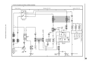
UNDERSTANDING TOYOTA WIRING DIAGRAMSINFORMATION #1READING TOYOTA ELECTRICAL WIRING DIAGRAMSU-1 Page 2
INFORMATION #2TOYOTA ELECTRICAL WIRING SYMBOLSUNDERSTANDING TOYOTA WIRING DIAGRAMSU-1 Page 3
UNDERSTANDING TOYOTA WIRING DIAGRAMSWORKSHEET #11. Describe the meaning of the "C13" in the diagram component Q.2. Describe the meaning of the "G-W" in diagram component R.3. Describe the meaning of the "2" in diagram component S.4. Describe the meaning of the "S/D" in diagram component T.5. Describe and identify the diagram component U.6. Describe and identify the diagram component V.7. Describe and identify the diagram component W.8. Describe and identify the diagram component X.9. Describe and identify the diagram component Y.10. Describe and identify the diagram component Z.WXYRQSVTUZU-1 Page 4
UNDERSTANDING TOYOTA WIRING DIAGRAMSWORKSHEET #21. Draw in GREEN the HORN CONTROL circuit from the battery to ground.2. Draw in RED the HORN circuit from the battery to ground.3. Draw in BLUE the part of the circuit that is common to both the control and load (horn) circuit.ZYXU-1 Page 5
UNDERSTANDING TOYOTA WIRING DIAGRAMSWORKSHEET #31. How will the circuit be affected if there were an open at point X.2. How will the circuit be affected if there were an open at point Y.3. How will the circuit be affected if there were an open at point Z.4. If the Horn Switch is OPEN, what voltage potential (Ground, Positive, or Electrically Dead)would you expect to find at point X, Y, & Z.5. If the Horn Switch is CLOSED, what voltage potential (Ground, Positive, or Electrically Dead)would you expect to find at point X, Y, & Z.12vZYXU-1 Page 6
TOYOTAHeadlightWorksheetsL-1 Page 1
TOYOTA HEADLIGHTSPRACTICE WORKSHEETL-1 Page 2
TOYOTA HEADLIGHTSWORKSHEET #11. Draw in GREEN the HEAD LAMP CONTROL circuit from the battery to ground.2. Draw in RED the LOW BEAM circuit from the battery to ground.3. Draw in BLUE the HIGH BEAM circuit from the battery to ground.L-1 Page 3
TOYOTA HEADLIGHTSWORKSHEET #21. THE HEADLAMP SWITCH IS PLACED IN THE FLASH POSITION2. Draw in GREEN the HEAD LAMP CONTROL circuit from the battery to ground.3. Draw in BLUE the circuit through the headlamps in the FLASH position from the battery toground.L-1 Page 4
TOYOTA HEADLIGHTSWORKSHEET #31. With the Headlamp Switch in the OFF position, what voltage would you expect to findat point V, W, X, Y, & Z.2. With the Headlamp Switch in the ON position, LOW BEAM position, what voltage would youexpect to find at point V, W, X, Y, & Z.3. With the Headlamp Switch in the ON position, HIGH BEAM position, what voltage would youexpect to find at point V, W, X, Y, & Z.4. How will the circuit be affected if there is an open at point V.5. How will the circuit be affected if there is an open at point W.6. How will the circuit be affected if there is an open at point X.7. How will the circuit be affected if there is an open at point Y.8. How will the circuit be affected if there is an open at point Z.XYWVZL-1 Page 5
TOYOTA HEADLIGHTSWORKSHEET #41. Trace in GREEN the portion of the circuit below that you suspect could be at fault.Both LOW BEAM HEADLAMPS do not work. High Beam and Flash positions workcorrectly. The tail lamps function correctly.2. Trace in RED the portion of the circuit below that you suspect could be at fault.The LEFT LOW BEAM HEADLAMP does not work. All other lamps function correctly inthe positions. The tail lamps function correctly.3. Trace in BLUE the portion of the circuit below that you suspect could be at fault.The RIGHT HIGH BEAM HEADLAMP does not work in any position. The tail lamps functioncorrectly.4. Trace in ORANGE the portion of the circuit below that you suspect could be at fault.The HEADLAMPS do not work in any position including flash. The tail lamps function correctly.L-1 Page 6
TOYOTATurn/Hazard LampsWorksheetsL-2 Page 1
TOYOTA TURN SIGNAL / HAZARD LAMPSREFERENCEL-2 Page 2
TOYOTA TURN SIGNAL / HAZARD LAMPSPRACTICE WORKSHEETL-2 Page 3
TOYOTA TURN SIGNAL / HAZARD LAMPSWORKSHEET #11. Draw in GREEN the RIGHT TURN LAMP circuit from the FUSE to GROUND.2. Draw in RED the LEFT TURN LAMP circuit from the FUSE to GROUND.L-2 Page 4
TOYOTA TURN SIGNAL / HAZARD LAMPSWORKSHEET #21. Draw in BLUE the HAZARD circuit from the FUSE to GROUND.L-2 Page 5
TOYOTA TURN SIGNAL / HAZARD LAMPSWORKSHEET #31. With the HAZARD SWITCH in the ON position, what voltage would you expect to findat point V, W, X, Y, & Z.2. With the RIGHT TURN SIGNAL SWITCH in the ON position, what voltage would youexpect to find at point V, W, X, Y, & Z.3 How will the circuit be affected if there is an open at point V.4. How will the circuit be affected if there is an open at point W.5. How will the circuit be affected if there is an open at point X.6. How will the circuit be affected if there is an open at point Y.7. How will the circuit be affectedif there is an open at point Z.XVWYZL-2 Page 6
TOYOTA TURN SIGNAL / HAZARD LAMPSWORKSHEET #41. Trace in GREEN the portion of the circuit below that you suspect could be at fault.TURN SIGNAL lamps do not work. The Hazard lamps function correctly.2. Trace in RED the portion of the circuit below that you suspect could be at fault.The LEFT TURN SIGNAL does not work. The Hazard lamps function normally.L-2 Page 7
TOYOTA TURN SIGNAL / HAZARD LAMPSWORKSHEET #51. Trace in BLUE the portion of the circuit below that you suspect could be at fault.The HAZARD LAMPS do not work. The Turn Signal Lamps function normally.2. Trace in ORANGE the portion of the circuit below that you suspect could be at fault. Both theHAZARD LAMPS and the TURN SIGNAL LIGHTS do not work in any Position.L-2 Page 8
TOYOTA TURN SIGNAL / HAZARD LAMPSWORKSHEET #61. Trace in BLUE the portion of the circuit below that you suspect could be at fault.The HAZARD LAMPS work the LEFT SIDE ONLY. The Turn Signal Lamps function normally.2. Trace in GREEN the portion of the circuit below that you suspect could be at fault. TheRIGHT REAR LAMP does not work with either the HAZARD LAMPS or TURN SIGNALLIGHTS in the ON position. The other three lamps flash.L-2 Page 9
TOYOTAStop LightWorksheetsL-3 Page 1
TOYOTA STOP LIGHTREFERENCEL-3 Page 2
TOYOTA STOP LIGHTSPRACTICE WORKSHEETL-3 Page 3
TOYOTA STOP LIGHTSWORKSHEET #11. Identify the HIGH MOUNT STOP LAMP circuit WITHOUT a Rear Spoiler. Draw that circuit inGREEN from the battery to ground.2. Identify the HIGH MOUNT STOP LAMP circuit WITH a Rear Spoiler. Draw that circuit in Bluefrom the battery to ground.3. Draw in RED the B current pathfrom the STOP LIGHT SWITCHto the Stop Light bulbs.L-3 Page 4
TOYOTA STOP LIGHTSWORKSHEET #21. THE STOP LIGHT SWITCH IS PLACED IN THE CLOSED POSITION. Draw the BLUE thePOSITIVE B SIDE of the circuit. Everything that is Positive (B ) with the Ign Key OFF.2. THE STOP LIGHT SWITCH IS PLACED IN THE OPEN POSITION. Draw the GREEN theGROUND SIDE of the circuit. Everything that is ground (Negative) with the Ign Key OFF.L-3 Page 5
TOYOTA STOP LIGHTSWORKSHEET #31. With the STOP LIGHT Switch in the OFF position, what voltage would you expect to findat point V, W, X, Y, & Z? (Note: Ignition Key is in the ON position)2. With the STOP LIGHT Switch in the ON position, what voltage would you expect to findat point V, W, X, Y, & Z? (Note: Ignition Key is in the OFF position)3. With a STOP LIGHT bulb burnedout, what voltage would you expectto find at point Y? B or Ground.WXYZVL-3 Page 6
TOYOTA STOP LIGHTSWORKSHEET #41. How will the circuit be affected if there is an open at point V?2. How will the circuit be affected if there is an open at point W?3. How will the circuit be affected if there is an open at point X?4. How will the circuit be affected if there is an open at point Y?5. How will the circuit be affected ifthere is an open at point Z?WXYVZL-3 Page 7
TOYOTA STOP LIGHTSWORKSHEET #51. On a vehicle without a rear spoiler. The stop lights do not work, but the high mount stoplamp works. Trace in GREEN the portion of the circuit below that could be at fault.2. On a vehicle with a rear spoiler. The high mount stop lamp does not work, but the stoplamps work fine. Trace in BLUE the portion of the circuit below that could be at fault.3. On a vehicle with a rear spoiler. A single stoplight in burned out, but the rear warninglamp indicator doesn't light. Trace in RED the portion of the circuit that could be at fault.4. On a vehicle without a rear spoiler.None of the stoplights work. Tracein ORANGE the portion of the circuitbelow that could be at fault.L-3 Page 8
TOYOTAAutomaticLight TurnoffWorksheetsL-4 Page 1
TOYOTA AUTO LIGHT TURNOFFREFERENCEL-4 Page 2
TOYOTA AUTO LIGHT TURNOFFPRACTICE WORKSHEETL-4 Page 3
TOYOTA AUTO LIGHT TURNOFFWORKSHEET #11. Draw in RED the wires that supply B and Ground to the Integration Relay.2. Draw in GREEN the INPUTS which are used by the Integration Relay to control the lights.3. Draw in BLUE the Control circuit from the battery to ground of the Headlamp Circuit.L-4 Page 4
TOYOTA AUTO LIGHT TURNOFFWORKSHEET #21. How will the circuit be affected if there is an open at point X.2. How will the circuit be affected if there is an open at point Y.YXL-4 Page 5
TOYOTADaytime Running LampsWorksheetsWill be providedin next release.L-5 Page 1
TOYOTARear Window DefoggerWorksheetsA-1 Page 1
TOYOTA REAR WINDOW DEFOGGERREFERENCEA-1 Page 2
TOYOTA REAR WINDOW DEFOGGERPRACTICE WORKSHEETA-1 Page 3
TOYOTA REAR WINDOW DEFOGGERWORKSHEET #11. Draw in GREEN the DEFOGGERCONTROL circuit from the battery toground.2. Draw in RED the DEFOGGER circuitfrom the battery to ground.3. Draw in BLUE the DEFOGGERLAMP circuit from the battery toground.A-1 Page 4
TOYOTA REAR WINDOW DEFOGGER1. With the Defogger Switch inthe OFF position, what voltagewould you expect to findat point V, W, X, Y, & Z ?2. With the Defogger Switch inthe ON position, what voltagewould you expect to find atpoint V, W, X, Y, & Z ?3. How will the circuit be affectedif there is an open at point V ?4. How will the circuit be affectedif there is an open at point W ?5. How will the circuit be affectedif there is an open at point X ?6. How will the circuit be affectedif there is an open at point Y ?7. How will the circuit be affectedif there is an open at point Z ?WORKSHEET #2WXYVZA-1 Page 5
TOYOTA REAR WINDOW DEFOGGERWORKSHEET #31. The rear window defroster switchlights up, but the rear windowdefroster does not work.Trace in BLUE the area(s) thatcould be at fault.2. The rear window defroster does notwork. The defroster switch lightdoes not light either.Trace in GREEN the area(s) thatcould be at fault.A-1 Page 6
TOYOTAPower WindowsWorksheetsA-2 Page 1
POWER WINDOWSREFERENCEA-2 Page 2
POWER WINDOWSPRACTICE WORKSHEETA-2 Page 3
POWER WINDOWSWORKSHEET #1While moving the window in the DOWNposition from the PASSENGER SUBSWITCH.1. Trace in RED the POSITIVE powerflow from the fuse to the motor.2. Trace in BLUE the NEGATIVE powerflow from the motor to ground.A-2 Page 4
POWER WINDOWSWORKSHEET #2While moving the PASSENGER SIDEWINDOW in the UP position from theMASTER SWITCH.1. Trace in RED the POSITIVE powerflow from the fuse to the motor.2. Trace in BLUE the NEGATIVE powerflow from the motor to ground.A-2 Page 5
POWER WINDOWSWORKSHEET #31. How will the circuit be affected if there is an open at point U.2. How will the circuit be affected if there is an open at point V.3. How will the circuit be affected if there is an open at point W.4. How will the circuit be affected if there is an open at point X.5. How will the circuit be affected if there is an open at point Y.6. How will the circuit be affected if there is an open at point Z.VWXYUZA-2 Page 6
POWER WINDOWSWORKSHEET #4The Passenger Window will not move UPor DOWN from the Master Window Switch.However, when the Sub Switch is used, thewindow will only move UP, and not DOWN.1. Trace in BLUE the areas where yoususpect the problem could be.A-2 Page 7
3. While moving the RIGHT FRONT window in the DOWN position from the SUB SWITCH.Trace in ORANGE the power flow from the fuse all the way to ground.2. While moving the RIGHT REAR window in the UP position from the SUB SWITCH.Trace in BLUE the power flow from the fuse to the motor.Trace in GREEN the power flow from the motor to ground.1. Trace in RED the B battery voltage from the fuse to each of the window SUB SWITCHES.POWER WINDOWSWORKSHEET #5A-2 Page 8
2. While moving the LEFT REAR window in the DOWN position from the MASTER SWITCH.Trace in ORANGE the power flow from the fuse all the way to ground.1. While moving the RIGHT REAR window in the UP position from the MASTER SWITCH.Trace in BLUE the power flow from the fuse to the motor.Trace in GREEN the power flow from the motor to ground.POWER WINDOWSWORKSHEET #6A-2 Page 9
4. Both Rear Windows will not roll up or down from either the Sub and Master Switches.Trace in ORANGE the areas where the problem could be.3. All of the Windows will not roll up or down from either the Sub and Master Switches.Trace in GREEN the areas where the problem could be.2. The Left Rear Window will not roll up or down from either the Sub and Master Switches.Trace in RED the areas where the problem could be.1. The Right Rear Window will not ro
UNDERSTANDING TOYOTA WIRING DIAGRAMS WORKSHEET #1 1. Describe the meaning of the "C13" in the diagram component Q. 2. Describe the meaning of the "G-W" in diagram component R. 3. Describe the meaning of the "2" in diagram component S. 4. Describe the meaning of the "S/D" in diagram component T. 5. Describe and identify the diagram component U .File Size: 2MBPage Count: 107