Transcription
COMPONENT PARTS SERIESInstallation, Operation &Maintenance InstructionsTABLE OF CONTENTSSection 1:Field Troubleshooting ProceduresSection 2:Field Control Replacement ProcedureECM Connections Diagram235ECM Blower MotorReplacement ControlsProgramming ProcessSERIES:BLOWER MOTORCLASS:ALLHz:UNIT OF MEASURE:LANGUAGE:DOCUMENT PART #:REVISION DATE:Installed By:60N/AENGLISH97B0004N035/04
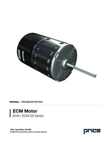
Section 1:GE ECM 2.3Field Troubleshooting ProceduresTroubleshooting GE ECM -Driven Systems:Caution:Disconnect power unit before removing or replacingconnectors, or servicing motor. Wait at least 5 minutesafter disconnecting power before opening motor.Symptom Cause/Procedure Motor rocks slightly when starting- This is normal start-up for ECM Motor wonʼt start- No movement - Check power at motor- Check low voltage (24 Vac R to C) at motor- Check low voltage connections (G, Y, W, R, C) at motor- Check for unseated pins in connectors on motor harness- Test with a temporary jumper between R - G- Check motor for tight shaft- Perform motor/control replacement check- Run Moisture Check Motor rocks, but wonʼt start- Check for loose or compliant motor mount- Make sure blower wheel is tight on shaft- Perform motor/control replacement check Motor oscillates up and down- It is normal for motor to oscillate being tested off ofblower with no load on shaft Motor starts, but runs erratically- Varies up and down or intermittent - Check line voltage for variation or “sag”- Check low voltage connections (G, Y, W, R, C) atmotor, unseated pins in motor harness connectors- Check “Bk” GE ICM2 for erratic CFM command (invariable speed applications)- Check-out system controls- Tʼstat?- Perform Moisture Check- “Hunts” or “puffs” at high CFM (speed) - Does removing panel or filter reduce “puffing”?- Reduce restriction- Reduce max airflow Evidence of Moisture- Motor failure or malfunction has occurred - Replace motor and perform Moisture Check- Evidence of moisture present inside air mover- Perform Moisture CheckDo:- Check-out motor, controls, wiring, and connectionsthoroughly before replacing motorDon’t:- Automatically assume the motor is badPage 2Do:- Orient connectors down so water canʼt get inDon’t:- Locate connectors above 7 and install drip loops4 oʼclock positionsDo:- Use authorized motor and control model #ʼsDon’t:- Replace one motor or control for replacement model #with another (unless an authorized replacement)Do:- Keep static pressure to a minimumDon’t- Use high pressure drop filtersDo:- Recommend high efficiency, low static some have1/2” H20 drop!FiltersDon’t:- Use restricted returnsDo:- Recommend keeping filters clean- Design duct work for min. static, max comfort- Look for and recommend duct work improvement,where necessary, in replacement- Size the equipment wiselyDon’t:- Oversize system, then compensate with low airflowDo:- Check orientation before inserting motorDon’t:- Plug in power connector backwardsConnectorsDon’t:- Force plugsMoisture Check Orientate connectors “down” Arrange harnesses with “drip loop” under motor Unplug condensate drain Check for low airflow (too much latent capacity) Check for undercharged condition Check and plug leaks in return ducts, cabinetComfort Check Check for proper airflow settings Obtain low static pressure for lowest noise Set low continuous-fan CFM Use humidistat and 2-speed cooling units Use zoning controls designed for the ECM thatregulate CFM Check if the Tʼstat is in a bad location
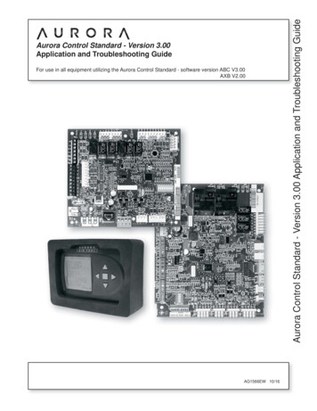
Section 2:GE ECM 2.3Field Control Replacement ProcedureReplacing ECM Control Module:To replace the control module for the GE variable speedindoor blower motor, you need to take the following steps.1. You MUST have the correct replacement module.The controls are factory programmed for specificoperating modes. Even though they look alike,different modules may have completely differentfunctionality.2. Begin by removing AC power from the furnace orairhandler being serviced. DO NOT WORK ON THEMOTOR WITH AC POWER APPLIED. Wait at least5 minutes after disconnecting AC power from theequipment before opening the motor.3. It is usually not necessary to remove the motor formthe blower assembly. However, it is recommendedthat the whole blower assembly, with the motor, beremoved from the furnace/airhandler. (Follow themanufacturerʼs procedures). Unplug the two cableconnectors to the motor. There are latches on eachconnector. DO NOT PULL ON THE WIRES. Theplugs remove easily when properly released.4. Locate the two standard 1/4” hex-head bolts at therear of the control housing (at the back end of thecontrol opposite the shaft end). Remove these twobolts from the motor and control assembly whileholding the motor in a way that will prevent themotor or control from falling when the bolts areremoved. If an ECM2.0 control is being replaced(recognized by an aluminum casting rather than adeep-drawn black steel can housing the electronics),remove the hex-head bolts. DO NOT REMOVE THETORX-HEAD SCREWS.5. The control module in now free of mechanicalattachment to the motor endshield, but is still connectedby a plug and three wires inside the control. Carefullyrotate the control to gain access to the plug at thecontrol end of the wires. With thumb and forefinger,reach the latch holding the plug to the control andrelease by squeezing the latch tab and the opposite sideof the connector plug and gently pulling the plug out ofthe connector socket in the control. DO NOT PULL ONTHE WIRES. GRIP THE PLUG ONLY.6. The control module is now completely detached fromthe motor. Verify with a standard ohmmeter that theresistance from each motor lead (in the motor plugjust removed) to the motor shell is 100K ohms.(Measure to unpainted motor endshield). If anymotor lead fails this test, do not proceed to install thecontrol module. THE MOTOR IS DEFECTIVE ANDMUST BE REPLACED. Installing the new controlmodule will cause it to fail also.7. Verify that the replacement control is correct for yourapplication. Refer to the manufacturerʼs authorizedreplacement list. USING THE WRONG CONTROLWILL RESULT IN IMPROPER OR NO BLOWEROPERATION. Orient the control module so that the3-wire motor plug can be inserted into the socket inthe control. Carefully insert the plug and press it intothe socket until it latches. A SLIGHT CLICK WILLBE HEARD WHEN PROPERLY INSERTED. Finishinstalling the replacement control per one of the threeparagraphs, 8a, 8b, or 8c.8a. IF REPLACING AN ECM2.0 CONTROL (controlin cast aluminum can with air vents on the back ofthe can) WITH AN ECM2.3 CONTROL (controlcontaining black potting for water protection in blackdeep-drawn steel case with no vents in the bottom ofthe can), locate the two through-bolts and plastic tabthat are packed with the replacement control. Insertthe plastic into the slot at the perimeter of the openend of the can so that the pin is located on the insideof the perimeter of the can. Rotate the can so thatthe tab inserts into the tab locator in the endshieldof the motor. Using the two through-bolts providedwith the replacement control, reattach the can to themotor. THE TWO THROUGH-BOLTS PROVIDEDWITH THE REPLACEMENT ECM2.3 CONTROLARE SHORTER THAN THE BOLTS ORIGINALLYREMOVED FROM THE ECM2.0 CONTROL ANDMUST BE USED IF SECURE ATTACHMENTOF THE CONTROL TO THE MOTOR IS TO BEACHIEVED. DO NOT OVERTIGHTEN THE BOLTS.8b. IF REPLACING AN ECM2.3 CONTROL WITHAN ECM2.3 CONTROL, the plastic tab andshorter through-bolts are not needed. The controlcan be oriented in two positions 180 apart. MAKESURE THE ORIENTATION YOU SELECT FORREPLACING THE CONTROL ASSURES THECONTROLʼS CABLE CONNECTORS WILL BELOCATED DOWNWARD IN THE APPLICATIONSO THAT WATER CANNOT RUN DOWN THECABLES AND INTO THE CONTROL. Simply orientthe new control to the motorʼs endshield, insert bolts,and tighten. DO NOT OVERTIGHTEN THE BOLTS.8c. IF REPLACING AN ECM2.0 CONTROL WITH ANECM2.0 CONTROL (It is recommended that ECM2.3controls be used for all replacements), the newcontrol must be attached to the motor using throughbolts identical to those removed with the originalcontrol. DO NOT OVERTIGHTEN THE BOLTS.9. Reinstall the lower/motor assembly into the HVACequipment. Follow the manufacturerʼs listed andsuggested procedures.Page 3
10. Plug the 16-pin control plug into the motor. The plugis keyed. Make sure the connector is properly seatedand latched11. Plug the 5-pin power connector into the motor.Even though the plug is keyed, OBSERVE THEPROPER ORIENTATION. DO NOT FORCE THECONNECTOR. It plugs very easily when properlyoriented. REVERSING THIS PLUG WILL CAUSEIMMEDIATE FAILURE OF THE CONTROLMODULE.12. Final installation check. Make sure the motor isinstalled as follows: Insert motor as far INTO theblower housing as possible. Make sure the belly bandisnʼt covering vent holes or on the control module.Orient motor connectors between the 4 and 8 oʼclockpositions when the blower is positioned in its finallocation and orientation. Add a drip loop to the cablesso that water cannot enter the motor by drainingdown the cables.The installation is now complete. Reapply the AC powerto the HVAC equipment and verify that the new motorcontrol module is working properly. Follow themanufacturerʼs procedures for disposition of the oldcontrol module.Page 4
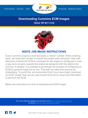
ECM Connections DiagramECM2Control Connector ***PWB Header AMP 770974-1PIN 0 BK/PWM11 Heat12 R13 EM/W214 Y/Y215 G16 Out *** Suggested Mating ConnectorHouseing AMP 770583-1Contact AMP 770904-1Power Connector *PWB Header AMP 1-350949-0PIN Description1Jumper PIN 1 to Pin for 120VACline input ONLY**23Chassis Ground4AC Line5AC Line* Suggested Mating ConnectorHouseing AMP 1-480763-1Contact AMP 350537-1ECM2.3Page 5
Page 6
Page 7
7300 S.W. 44th StreetOklahoma City, OK 73179Phone: 405-745-6000Fax: 04N03ClimateMaster works continually to improve its products. As a result, the design and specifications of each product at the time for order may be changed withoutnotice and may not be as described herein. Please contact ClimateMasterʼs Customer Service Department at 1-405-745-6000 for specific information on the currentdesign and specifications. Statements and other information contained herein are not express warranties and do not form the basis of any bargain between the parties,but are merely ClimateMasterʼs opinion or commendation of its products. ClimateMaster, Inc. 2003
Troubleshooting GE ECM -Driven Systems: Caution: Disconnect power unit before removing or replacing connectors, or servicing motor. Wait at least 5 minutes after disconnecting power before opening motor. Symptom Cause/Procedure Motor rocks slightly when starting - This is normal start-up for ECM Motor wonʼt start - No movement -