Transcription
For use in all equipment utilizing the Aurora Control Standard - software version ABC V3.00AXB V2.00AG1566EW 10/16Aurora Control Standard - Version 3.00 Application and Troubleshooting GuideAurora Control Standard - Version 3.00Application and Troubleshooting Guide
AURORA CONTROL STANDARD - VERSION 3.00 APPLICATION AND TROUBLESHOOTING GUIDETable of ContentsIntroduction. . . . . . . . . . . . . . . . . . . . . . . . . . . . . . . . . . . . . . . . . . . . . . . . . . . . . . . . . . . . . . . . . . . . . 4Aurora Interface Diagnostic (AID) Tool . . . . . . . . . . . . . . . . . . . . . . . . . . . . . . . . . . . . . . . . . . . . . . 4Control Board Features . . . . . . . . . . . . . . . . . . . . . . . . . . . . . . . . . . . . . . . . . . . . . . . . . . . . . . . . . . . 5Safety Features. . . . . . . . . . . . . . . . . . . . . . . . . . . . . . . . . . . . . . . . . . . . . . . . . . . . . . . . . . . . . . . . . . 5Modes of Operation . . . . . . . . . . . . . . . . . . . . . . . . . . . . . . . . . . . . . . . . . . . . . . . . . . . . . . . . . . . . . . 6Field Selectable Options . . . . . . . . . . . . . . . . . . . . . . . . . . . . . . . . . . . . . . . . . . . . . . . . . . . . . . . . . . 8Thermistor Data . . . . . . . . . . . . . . . . . . . . . . . . . . . . . . . . . . . . . . . . . . . . . . . . . . . . . . . . . . . . . . . . 10Wiring Schematics . . . . . . . . . . . . . . . . . . . . . . . . . . . . . . . . . . . . . . . . . . . . . . . . . . . . . . . . . . . . . . .11Control Board Layout. . . . . . . . . . . . . . . . . . . . . . . . . . . . . . . . . . . . . . . . . . . . . . . . . . . . . . . . . . . . 15Preliminary Checkout Procedure . . . . . . . . . . . . . . . . . . . . . . . . . . . . . . . . . . . . . . . . . . . . . . . . . . 16Troubleshooting Checklist . . . . . . . . . . . . . . . . . . . . . . . . . . . . . . . . . . . . . . . . . . . . . . . . . . . . . . . 17Control Board Troubleshooting Steps . . . . . . . . . . . . . . . . . . . . . . . . . . . . . . . . . . . . . . . . . . . . . . 18Control Board Troubleshooting Flow Charts. . . . . . . . . . . . . . . . . . . . . . . . . . . . . . . . . . . . . . . . . 20Communicating Thermostat Troubleshooting Guide . . . . . . . . . . . . . . . . . . . . . . . . . . . . . . . . 32-33Control Board Signals . . . . . . . . . . . . . . . . . . . . . . . . . . . . . . . . . . . . . . . . . . . . . . . . . . . . . . . . . 34-36Jumping the Control Board . . . . . . . . . . . . . . . . . . . . . . . . . . . . . . . . . . . . . . . . . . . . . . . . . . . . . 37-39Water Side Analysis: Heat of Extraction/Rejection . . . . . . . . . . . . . . . . . . . . . . . . . . . . . . . . . . . . 40Superheat/Subcooling . . . . . . . . . . . . . . . . . . . . . . . . . . . . . . . . . . . . . . . . . . . . . . . . . . . . . . . . . 41-42Revision Guide . . . . . . . . . . . . . . . . . . . . . . . . . . . . . . . . . . . . . . . . . . . . . . . . . . . . . . . . . . . . . . . . . 45
AURORA CONTROL STANDARD - VERSION 3.00 APPLICATION AND TROUBLESHOOTING GUIDEIntroductionThe Aurora Control System is a complete residential andcommercial comfort system that brings all aspects of the HVACsystem into one cohesive module network. Aurora will use theModbus communication protocol to communicate betweenmodules. Each module will contain the logic to control all featuresthat are connected to the module. The Aurora Base Control(ABC) has two Modbus channels. The first channel is configuredas a master for connecting to devices such as a communicatingthermostat, expansion board, or other linked devices. The secondchannel is configured as a link for connecting the Aurora InterfaceDiagnostic Tool (AID Tool).General Operating ParametersABC Part NumberRelay Contact Ratings17X553-07Reversing Valve (K1) 10A at 120VAC/30VDCCompressor (K2) 10A at 120VAC/30VDCCompressor Speed (K3) N.O. 10A, N.C. 3A at 125VACBlower Motor (K4) 10A at 120VAC/30VDCAlarm/Reheat (K5) 10A at 120VAC/30VDCAccessory Output (K6) N.O. 10A, N.C. 3A at 125VACOperating Environment: -20 F to 158 F and up to 95% relativehumidity, non-condensingShipping and Storage Environment: -40 F to 185 F and up to 95%relative humidity, non-condensingPower Requirements: input voltage range of 18 to 30 VACPower Consumption: normal 12 VA at 24 VAC, maximum 20 VA at24 VACAgency Approvals: ULAXB Part Number17X557-03GroundingThe control board has plastic standoffs. The ground connectionfrom “C” is required.Aurora Interface Diagnostic (AID) ToolAurora Input-Output DiagnosticsTroubleshooting the Aurora logic board can be accomplished usingnothing more than a couple of jumper wires and a volt meter. Theprocess can be simplified with the use of the Aurora InterfaceDiagnostic Tool (AID Tool). The AID Tool allows the user to seelockout and fault history information, thermostat inputs, sensorinputs, system outputs, timer, etc.Aurora ABC CheckoutBefore replacing the Aurora ABC control board the propertroubleshooting steps must be taken to ensure that the board is theroot cause. On the following pages are several flow charts that willassist in checking the control board. If it is found that the controlboard is faulty, contact technical services for a replacement part.Compressor Will Not Start Without AID Tool – Pages 20-21 With AID Tool – Pages 22-23ECM Blower Will Not Start Without AID Tool – Pages 24-25 With AID Tool – Pages 26-274
AURORA CONTROL STANDARD - VERSION 3.00 APPLICATION AND TROUBLESHOOTING GUIDEControl FeaturesSingle or Dual Capacity CompressorsOther Control FeaturesEither single or dual capacity compressors can be operated. ECM Blower Motor OptionA traditional ECM blower motor can be driven directly using theonboard PWM output. Four blower speeds are available, basedupon the G, Y1 (low), and Y2 (high), and Aux input signals to theboard. The blower speeds can be changed either by the ECMmanual configurations mode (except Aux) method (see ECMConfiguration Mode topic) or by using the Aurora AID Tool directly.All blower speeds can be set to the same speed if desired.5-Speed ECM Blower Motor OptionA 5-Speed ECM blower motor will be driven using the ABC outputsfor Fan (F), Stage 1 Compressor (CC), Stage 2 Compressor(CC2), and Electric Heat 1 (EH1). These signals can drive any ofthe 5 available pre-programmed blower speeds on the motor.Random start at power upAnti-short cycle protectionHigh and low pressure cutoutsLoss of chargeWater coil freeze detectionAir coil freeze detectionOver/under voltage protectionCondensate overflow sensorLoad shedDehumidificationEmergency shutdownHot gas reheat operationDiagnostic LEDTest mode push button switchTwo auxiliary electric heat outputsAlarm outputAccessory output with N.O. and N.C.Modbus communication (primary)Modbus communication (secondary)Safety FeaturesThe following safety features are provided to protect thecompressor, heat exchangers, wiring, and other components fromdamage caused by operation outside of design conditions.Lockout With Emergency Heat - if the control is locked out inthe heating mode, and a Y2 or W input is received, the controlwill operate in the emergency heat mode while the compressor islocked out. The first emergency heat output will be energized ten(10) seconds after the W input is received, and the blower will shiftto high speed. If the control remains locked out, and the W input ispresent, additional stage of emergency heat will stage on after two(2) minutes. When the W input is removed, all of the emergencyheat outputs will turn off, and the ECM blower will shift to lowspeed and PSC blower motor output will remain on.Fuse – a 3 amp automotive type plug-in fuse provides protectionagainst short circuit or overload conditions.Anti-Short Cycle Protection – 4 minute anti-short cycle protectionfor the compressor.Random Start – 5 to 80 second random start upon power up.High Pressure – fault is recognized when the Normally ClosedHigh Pressure Switch, P4-9/10 opens, no matter how momentarily.The High Pressure Switch is electrically in series with theCompressor Contactor and serves as a hard-wired limit switch ifan overpressure condition should occur.Fault Retry – in the fault condition, the control will stage off theoutputs and then “try again” to satisfy the thermostat Y inputcall. Once the thermostat input calls are satisfied, the control willcontinue on as if no fault occurred. If 3 consecutive faults occurwithout satisfying the thermostat Y input call, then the control willgo to Lockout mode.Low Pressure - fault is recognized when the Normally ClosedLow Pressure Switch, P4-7/8 is continuously open for 30 seconds.Closure of the LPS any time during the 30 second recognitiontime restarts the 30 second continuous open requirement. Acontinuously open LPS shall not be recognized during the 2 minutestartup bypass time.Loss of Charge – fault is recognized when the Normally Closed LowPressure Switch, P4-7/8 is open prior to the compressor starting.Lockout – when locked out, the blower will operate continuously in“G” blower speed setting, and PSC blower motor output will remainon. The Alarm output (ALM) and Lockout output (L) will be turned on.The fault type identification display LED1 (Red) shall flash the faultcode. To reset lockout conditions with SW2-8 On, thermostat inputs“Y1”, “Y2”, and “W” must be removed for at least three (3) seconds.To reset lockout conditions with SW2-8 Off, thermostat inputs “Y1”,“Y2”, “W”, and “DH” must be removed for at least three (3) seconds.Lockout may also be reset by turning power off for at least 5 secondsor by enabling the emergency shutdown input for at least 3 seconds.Condensate Overflow - fault is recognized when the impedancebetween this line and 24 VAC common or chassis ground dropsbelow 100K ohms for 30 seconds continuously.5
AURORA CONTROL STANDARD - VERSION 3.00 APPLICATION AND TROUBLESHOOTING GUIDESafety FeaturesFreeze Detection - set points shall be either 30 F or 15 F. Whenthe thermistor temperature drops below the selected set point,the control shall begin counting down the 30 seconds delay. Ifthe thermistor value rises above the selected set point, then thecount should reset. The resistance value must remain below theselected set point for the entire length of the appropriate delay tobe recognized as a fault. This fault will be ignored for the initial 2minutes of the compressor run time.Compressor Current Monitoring - Compressor currentmonitoring will be used to monitor the compressor operation anddetect certain faults based on the level of current read by theboard. These faults are Welded Contactor, Open Circuit, OpenStart Circuit, and Open Run Circuit.Over/Under Voltage Shutdown - An over/under voltage conditionexists when the control voltage is outside the range of 18 VAC to30 VAC. If the over/under voltage shutdown lasts for 15 minutes,the lockout and alarm relay will be energized. Over/under voltageshutdown is self-resetting in that if the voltage comes back withinrange of 18 VAC to 30 VAC for at least 0.5 seconds, then normaloperation is restored.Freeze Detection (Air Coil) - uses the FP2 input to protectagainst ice formation on the air coil. The FP2 input will operateexactly like FP1 except that the set point is 30 degrees and is notfield adjustable.Modes of OperationPower UpBlower (G)The unit will not operate until all the inputs and safety controlsare checked for normal conditions. The unit has a 5 to 80 secondrandom start delay at power up. Then the compressor has a 4minute anti-short cycle delay after the random start delay.The blower will start immediately upon receiving a thermostat Gcommand. If there are no other commands from the thermostatthe ECM will run on low speed until the G command is removed.Regardless of blower input (G) from the thermostat, the blower willremain on low speed for 30 seconds at the end of each heating cycle.StandbyCooling OperationIn standby mode, Y1, Y2, W, DH, and G are not active. Input Omay be active. The blower and compressor will be off.In all cooling operations, the reversing valve directly tracks the Oinput. Thus, anytime the O input is present, the reversing valve willbe energized.Heating OperationHeating, 1st Stage (Y1)Cooling, 1st Stage (Y1,O)The blower is started in “G” blower speed setting immediatelyand the compressor is energized 10 seconds after the Y1 inputis received. The ECM blower motor is switched to low speed 15seconds after the Y1 input.The blower is started in “G” blower speed setting immediatelyand the compressor is energized 10 seconds after the Y1 inputis received. The ECM blower motor is switched to low speed 15seconds after the Y1 input.Heating, 2nd Stage (Y1, Y2)Cooling, 2nd Stage (Y1, Y2, O)The compressor will be staged to full capacity 20 seconds afterY2 input is received. The ECM blower will shift to high speed 15seconds after the Y2 input is received.The compressor will be staged to full capacity 20 seconds afterY2 input was received. The ECM blower will shift to high speed 15seconds after the Y2 input was received.Heating, 3rd Stage (Y1, Y2, W)Blower (G)The hot water pump is de-energized and the first stage of electricheat is energized 10 seconds after the W command is received.If the demand continues the second stage of electric heat will beenergized after 5 minutes.The blower will start immediately upon receiving a thermostat Gcommand. If there are no other commands from the thermostatthe ECM will run on low speed until the G command is removed.Regardless of blower input (G) from the thermostat, the blower willremain on low speed for 30 seconds at the end of each heating,cooling, emergency heat, and reheat cycle.Emergency Heat (W)The blower will be started in “G” blower speed setting, 10 secondslater the first stage of electric heat will be turned on. 5 secondsafter the first stage of electric heat is energized the blower will shiftto high speed. If the emergency heat demand is not satisfied after2 minutes the second electric heat stage will be energized.Dehumidification (Y1, O, DH or Y1, Y2, O, DH)When a DH command is received from the thermostat during acompressor call for cooling the ECM blower speed will be reducedby 15% to increase dehumidification.6
AURORA CONTROL STANDARD - VERSION 3.00 APPLICATION AND TROUBLESHOOTING GUIDEModes of Operation cont.Blower SpeedSelection NumberPWM %DehumidificationPWM 9574129876AXB OperationPump LinkingPump linking is used when two or more heat pumps share acommon loop pump. Loop pump linking will work with any unitusing an AXB control board. Pump linking on the new controlsis also compatible with older Premier board type controls used inearlier product offerings. When the pump share input is activatedthe loop pump output relay (K5) will be immediately energized andthe variable speed pump output will run the pump at 100%.Hot Water Generation (Desuperheater) OperationHot water generation will use the hot discharge gas from thecompressor to assist in making hot water. When the compressorfirst starts there will be a two minute sample period where thecontrol board checks the hot water temperature. In the heatingmode the hot water pump will run anytime the compressor isrunning, there is no requirement for electric heat, and the leavinghot water temperature is below the hot water set point. If at anytime the hot water temp rises above the set point the pump willbe turned off for 15 minutes, at the end of the 15 minutes thehot water pump will be run once again to check the temperature.In the cooling mode a special algorithm has been developedto prevent the hot water pump from running if discharge gastemperatures are too low for the system to add heat to the water.All other logic for cooling mode is the same as for heating. The hotwater set point has an adjustable range of 100 F to 140 F.Emergency ShutdownFour (4) seconds after a valid ES input, P2-7 is present, all controloutputs will be turned off and remain off until the emergencyshutdown input is no longer present. The first time that thecompressor is started after the control exits the emergencyshutdown mode, there will be an anti-short cycle delay followed bya random start delay. Input must be tied to common to activate.Continuous Blower OperationThe blower output will be energized any time the control has a Ginput present, unless the control has an emergency shutdown inputpresent. The blower output will be turned off when G input is removed.Energy MonitoringUsing current transducers attached to the compressor, blower,and aux heat (field installed) the AXB control board can calculateapproximate energy usage of the equipment. This calculation canbe displayed on a thermostat.Load ShedThe LS input disables all outputs with the exception of the bloweroutput. When the LS input has been cleared, the anti-short cycletimer and random start timer will be initiated. Input must be tied tocommon to activate.Refrigeration SensingUsing suction pressure, discharge pressure, heating liquid linetemperature, and cooling liquid line temperature (FP1) the controlcan calculate and display Evaporator temperature, Condensertemperature, Superheat, and Subcooling. These values can beused to aid diagnostics of the refrigeration system.Hot Gas Reheat OperationReheat (DH, SW2-8 OFF)When SW2-8 is set to the “OFF” position the Alarm/Reheat Outputwill be used to control a hot gas reheat valve. If the control receivesa DH command and there is no requirement from the space forheating or cooling (Y1 or Y2 command) the control will operatein second stage cooling mode. 30 seconds after the compressoroutput (CC) energizes, the Alarm/Reheat output will be energized.The control will run reheat until the requirement has been satisfiedor there is a command from the space for heating or cooling (Y1,Y2, or both). If the command from the space is for cooling (Y1, Y2,O) the control will simply de-energize the Alarm/Reheat output andcool the space without disabling the compressor. If there is stilla command for dehumidification from the space once cooling issatisfied, the control re-energizes the Alarm/Reheat output withoutdisabling the compressor output. If the command from the spaceis for heating the control will disable the compressor output andde-energize the Alarm/Reheat output. After the compressor shortcycle delay is satisfied the control will re-start the unit in the heatingmode. If there is still a command for dehumidification from the spaceonce heating is satisfied the control will once again shut downthe compressor for the compressor short cycle delay. Once thecompressor short cycle delay has satisfied, the sequence for startingthe reheat cycle will be repeated.Performance MonitoringUsing entering water temperature, leaving water temperature, waterflow rate in GPM, total unit power (energy monitoring required), andwater factor the heat of extraction (HE) and heat of rejection (HR)can be calculated for the heat pump. The water factor is selectablewith the AID tool for antifreeze 485 or water 500.Home Automation InputsThe AXB offers two dry contact inputs for field use. Using theAID tool these two inputs can be setup to display several differentfaults: Home Automation, Security Alarm, Sump Alarm, Smoke/COAlarm, or Dirty Filter.Smart GridA dry contact smart grid input is available that allows forconnection from the power company. The AID tool can be used toselect Go To.7
AURORA CONTROL STANDARD - VERSION 3.00 APPLICATION AND TROUBLESHOOTING GUIDEField Selectable OptionsCycle with Compressor - The accessory relay will cycle withthe compressor output.Field Selectable Options via HardwareDIP Switch (SW1) – Test/Configuration Button (See SW1Water Valve Slow Opening - The accessory relay will cycle anddelay both the blower and compressor output for 90 seconds.Operation Table)Test ModeSW2-6The control is placed in the test mode by holding the push buttonswitch SW1 for 2 - 5 seconds. In test mode most of the controltimings will be shortened by a factor of sixteen (16). LED3 (green)will flash at 1 second on and 1 second off. Additionally, whenentering test mode LED1 (red) will flash the last lockout one time.Test mode will automatically time out after 30 minutes.SW2-7SW2-8CC Operation – selection of single or dual capacitycompressor. On Single Stage; Off Dual CapacityLockout and Alarm Outputs (P2) – selection of acontinuous or pulsed output for both the LO and ALMOutputs. On Continuous; Off PulsedReheat Operation – On Normal; Off ReheatHumidificationTest mode can be exited by pressing and holding the SW1 buttonfor 2 to 5 seconds or by cycling the power.When a humidifier is installed with a communicating thermostat theaccessory relay on the ABC control board must be used. SettingABC DIP switches SW2-4 OFF and SW2-5 ON the ABC accessoryrelay will cycle based on a humidification (H) command.Test mode will automatically be exited after 30 minutes.ECM Configuration ModeAlarm Jumper Clip SelectionThe control is placed in ECM configuration mode by holding thepushbutton switch SW1 for 5 to 10 seconds, the high, medium,and low ECM speeds can be selected by following the LEDdisplay lights. LED2 (yellow) will fast flash when entering ECMconfiguration. When setting “G” speed LED3 (green) will becontinuously lit, for low speed LED1 (red) will be continuouslylit, and for high speed both LED3 (green) and LED1 (red) will becontinuously lit. During ECM configuration mode LED2 (yellow)will flash each of the 12 possible blower speeds 3 times. Whenthe desired speed is flashed press SW1, LED2 will fast flash untilSW1 is released. “G” speed has now been selected. Next selectlow speed, and high speed blower selections following the sameprocess above. After third selection has been made, the control willexit the ECM configuration mode.From the factory, ALM is connected to 24 VAC via JW2. By cuttingJW2, ALM becomes a dry contact connected to ALG.ECM Blower SpeedsThe blower speeds can be changed either by using the ECMmanual configurations mode method or by using the AuroraAID Tool directly (see Instruction Guide: Aurora Interface andDiagnostic (AID) Tool topic).DIP Switch (SW1-AXB)(Factory default ia all ON)SW1-1 Modbus address selection – On 3; Off 4SW1-2 Spare – On Normal; Off Not UsedSW1-3 Spare – On Normal; Off Not UsedSW1-3 Spare. On Normal; Off Not UsedSW1-4 AXB Accessory Relay Operationand 1-5Reset Configuration ModeThe control is placed in reset configuration mode by holding thepush button switch SW1 for 50 to 60 seconds. This will resetall configuration settings and the EEPROM back to the factorydefault settings. LED3 (green) will turn off when entering resetconfiguration mode. Once LED3 (green) turns off release SW1 andthe control will reset.Access Relay OperationCycle with FanCycle with CC or Variable Speed 1-12Cycle with CC2 or Variable Speed 7-12Cycles with DH from ABC BoardDIP Switch (SW2-ABC)SW2-1SW2-2SW2-3SW2-4and 2-5FP1 Selection – Temperature limit setting for freezedetection. On 30 F; Off 15 F.FP2 Selection – Future UseRV – O/B - thermostat type. Heat pump thermostatswith “O” output in cooling or “B” output in Heating can beselected. On O; Off B.ABC Accessory Relay Operation (P2)Access Relay OperationCycle with FanCycle with CompressorWater Valve Slow OpeningCycles with H command fromcommunicating ONOFFSW1-5ONONOFFOFFDehumidificationWhen an output is needed for dehumidification the accessory relayon the AXB control board must be used. Setting AXB DIP switchesSW1-4 and SW1-5 both to OFF on the AXB accessory relay willcycle with either the hardware DH input on the ABC or with acommunicating DH command from the thermostat.Field Selectable Options via Software(Selectable via the Aurora AID Tool)ECM Blower SpeedsA traditional ECM blower motor can be driven directly using theonboard PWM output. Four blower speeds are available, basedupon the G (low), Y1 (med), and Y2 (high), and Aux input signalsto the board. The blower speeds can be changed either by theECM manual configurations mode (except Aux) method (see ECMConfiguration Mode topic) or by using the Aurora AID Tool directly.All blower speeds can be set to the same speed if desired.Cycle with Blower - The accessory relay will cycle with theblower output.8
AURORA CONTROL STANDARD - VERSION 3.00 APPLICATION AND TROUBLESHOOTING GUIDEField Selectable Options cont.LED DisplaysSlow Flash 1 second on and 1 second offFast Flash 100 ms on and 100 ms offFlash Code 100 ms on and 400 ms off with a 2 second pause between packagesSW1 OperationHolding SW12 to 5 seconds5 to 10 seconds50 to 60 seconds 60 secondsDescription of OperationEnter Test ModeEnter ECM Configure ModeReset Configure Mode (factory default)SW1 Operation CancelLEDGreen LED Slow FlashYellow LED OffYellow LED OffYellow LED Back to Normal“SW1 operation cancel,” holding SW1 for longer than 60 seconds operation will be cancelled. Yellow LED will go back to normal operation.Status LED (LED3, Green)Fault LED (LED1, Red)Description of OperationNormal ModeControl is Non-functionalTest ModeLockout ActiveDehumidification Mode(Reserved)(Reserved)Load ShedESDOn PeakABC Basic FaultsLEDReset/Description of OperationFlashLockoutRemoveCode *Normal - No FaultsOFF—Fault-Input1NoAutoFault-High Pressure2YesHard or SoftFault-Low Pressure3YesHard or SoftFault-Freeze Detection FP24YesHard or SoftFault-Freeze Detection FP15YesHard or SoftFault-Condensate Overflow7YesHard or SoftFault-Over/Under Voltage Shutdown8NoAutoFault-FP111YesHard or SoftFault-Compressor Monitor10YesHard or or14YesHard or SoftAlert-HotWtr (AID Only)15NoAutoFault-VarSpdPump16NoAutoNot Error19NoAutoAlarm - Low Loop Pressure21NoAutoAlarm - Home Automation 123NoAutoAlarm - Home Automation 224NoAutoNOTES: * All codes 11 use long flash for tens digit and short flash for the onesdigit. 20, 30, 40, 50 etc. are skipped.Alert is a noncritical sensor or function that has failed. Normal operation of theheat pump is maintained but service is desired at some point.ABC & AXB Advanced FaultsNormal and Test Mode Timing and DelaysEventRandom Start DelayCompressor On DelayBlower Off DelayCompressor Short Cycle Delay(minimum off time)Compressor Minimum On TimeFault Recognition Delay - High PressureFault Recognition Delay - Freeze DetectionFault Recognition Delay - Low PressureFault Recognition Delay - CondensateOverflowFreeze Detection Bypass at StartupLow Pressure Bypass at StartupAuxiliary Heat Staging DelayEmergency Heat Staging DelayThermostat Call Recognition TimeCompressor Minimum Stage TimeReheat Delay TimeConfiguration LED (LED2, Yellow)Description of OperationNo Software OverwrittenDIP Switch was OverwrittenECM Configuration ModeReset Configuration ModeConfiguration LED, YellowFlashing ECM SettingSlow FlashFast FlashOFFFault Retries Before LockoutType of FaultHigh PressureLow PressureFreeze Detection 1 - (Coax)Freeze Detection 2 - (Air coil)Condensate OverflowOver/Under Voltage ShutdownCompressor MonitorFreeze Detection Sensor Error(Sensor is out of range)Fault LED, GreenONOFFSlow FlashFast FlashFlash Code 2Flash Code 3Flash Code 4Flash Code 5Flash Code 6Flash Code 7Total Tries Before Lockout3 Retries3 Retries3 Retries3 Retries3 RetriesNo LockoutNo RetryNo Retry9NormalTiming5 to 80 seconds5 seconds30 secondsTest ModeTiming 1 second 1 second 2 seconds4 minutes 15 seconds120 seconds 1 second30 seconds30 seconds 5 seconds 1 second30 seconds30 seconds30 seconds30 seconds2 minutes2 minutes5 minutes2 minutes2 seconds15 seconds30 seconds30 seconds30 seconds 20 seconds 7.5 seconds2 seconds2 seconds30 seconds
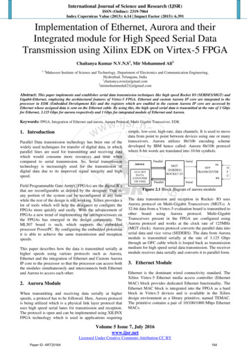
AURORA CONTROL STANDARD - VERSION 3.00 APPLICATION AND TROUBLESHOOTING GUIDEThermistor DataTemp ,58626,83126,099Temp 7,163Temp 82,4382,39010Temp 963947931Temp 45438431425419412
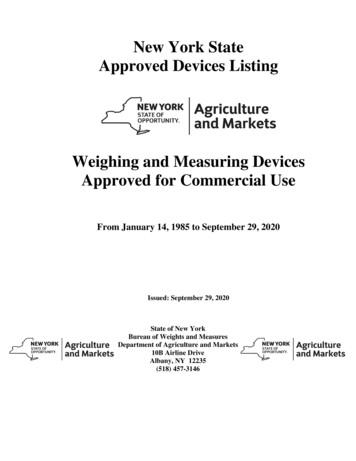
AURORA CONTROL STANDARD - VERSION 3.00 APPLICATION AND TROUBLESHOOTING GUIDETypical Wiring SchematicsCommercial Aurora with ECM MotorT3Note 4T
5-Speed ECM Blower Motor Option A 5-Speed ECM blower motor will be driven using the ABC outputs for Fan (F), Stage 1 Compressor (CC), Stage 2 Compressor (CC2), and Electric Heat 1 (EH1). These signals can drive any of the 5 available pre-programmed blower speeds on the motor. Control Features Other Control Features Random start at power up