Transcription
21V51U-843Integrated Two-Stage/Variable Speed MotorHot Surface Ignition Control KitINSTALLATION INSTRUCTIONSOperator: Save these instructions for future use!FAILURE TO READ AND FOLLOW ALL INSTRUCTIONS CAREFULLY BEFOREINSTALLING OR OPERATING THIS CONTROL COULD CAUSE PERSONALINJURY AND/OR PROPERTY DAMAGE.DESCRIPTIONThe kit Includes:Signals interpreted during continual surveillance of the twostage thermostat and flame sensing element initiate automaticignition of the burner, sensing of the flame, and system shutoffduring normal operation. 50V51-843 Ignition Control Module 21D64-2 Ignitor Kit Set of Interconnect Harnesses (for Goodman)The 50V51-843 is a two-stage automatic gas interrupted ignitioncontrol employing a microprocessor to continually monitor,analyze, and control the proper operation of the gas burner andinducer. The 50V51-843 provides signals for proper operationof a variable fan speed circulator blower.The control incorporates system fault analysis for quick gasflow shutoff, coupled with automatic ignition retry upon sensinga fault correction.PRECAUTIONSInstallation should be done by a qualified heating and airconditioning contractor or licensed electrician.WARNINGIf in doubt about whether your wiring is millivolt, line, or low voltage,have it inspected by a qualified heating and air conditioningcontractor or licensed electrician.Do not exceed the specification ratings.All wiring must conform to local and national electrical codesand ordinances.This control is a precision instrument, and should be handledcarefully. Rough handling or distorting components could causethe control to malfunction.Following installation or replacement, follow manufacturer’srecommended installation/service instructions to ensure properoperation.CAUTIONDo not short out terminals on gas valve or primarycontrol. Short or incorrect wiring may damage ecifications.2Timing Table & Definitions.2Installation.3Mounting & WiringOption Switch Settings.4Mounting Hole Template.5Wiring .6Operation.8Troubleshooting.8Failure to comply with the followingwarnings could result in personal injuryor property damage.FIRE HAZARD Do not exceed the specified voltage. Protect the control from direct contact with water(dripping, spraying, rain, etc.). If the control has been in direct contact with water,replace the control. Label all wires before disconnection when servicingcontrols. Wiring errors can cause improper anddangerous operation. Route and secure wiring away from flame.SHOCK HAZARD Disconnect electric power before servicing. Ensure proper earth grounding of appliance. Ensure proper connection of line neutral and linehot wires.EXPLOSION HAZARD Shut off main gas to appliance until installation iscomplete.PART NO. 37-7115001emerson.com/white-rodgersReplaces 37-7115D2005
SPECIFICATIONSELECTRICAL RATINGS [@ 77 F (25 C)]:Input Voltage: 25 VAC, 60 Hz (Class II transformer required)Max. Input Current @ 25 VAC: 500mA MVRelay Load Ratings:Gas Valve Relays: 1.5 amps @ 25 VAC, 60 HzInducer Relays: 2.2 FLA - 3.5 LRA @120 VACIgnitor Relay: 4.0 amps @ 120 VAC (Resistive)Humidifier/EAC: 120 VAC/1 AmpFlame Current Requirements:Minimum current to insure flame detection: 0.3 µa DC*Maximum current for non-detection: 0.1 µa DC*Maximum allowable leakage resistance: 100 M ohms*Measured with a DC microammeter in the flame probe leadOPERATING TEMPERATURE RANGE:-40 to 175 F (-40 to 80 C)HUMIDITY RANGE:5% to 93% relative humidity (non-condensing)Timing Specs: (@ 60 Hz)maximumFlame Establishing Time:0.8 secFlame Failure Response Time:2.0 secsGases Approved: Natural, Manufactured, Mixed, LiquefiedPetroleum, and LP Gas Air Mixtures are all approved for use.21V51U-843 TIMING TABLE(All times are in seconds, unless noted otherwise)EventPre-purge TimeDefinitionThe period of time intended to allow for the dissipation of any unburnedgas or residual products of combustion at the beginning of a furnaceoperating cycle prior to initiating ignition50M51-84315Igniter Warm-up TimeThe length of time allowed for the igniter to heat up prior to the initiationof gas flow.17Trial for Ignition Period (TFI)The period of time between initiation of gas flow and the action toshut off the gas flow in the event of failure to establish proof of thesupervised ignition source or the supervised main burner flame.4Ignition Activation Period (IAP)The period of time between energizing the main gas valve anddeactivation of the ignition means prior to the end of TFI3RetriesThe additional attempts within the same thermostat cycle for ignitionwhen the supervised main burner flame is not proven within the firsttrial for ignition period.Valve Sequence periodValve sequence period equals 4 seconds trial for ignition period x(1 initial try 2 retries) 12 seconds.12Inter-purgeThe period of time intended to allow for the dissipation of any unburnedgas or residual products of combustion between the failed trial forignition and the retry period.60Post-purge TimeThe period of time intended to allow for the dissipation of any unburnedgas or residual products of combustion at the end of a furnace burneroperating cycle. Post-purge begins at the loss of flame sense.15Lock-Out TimeANSI standard rated module timing.300Heat Delay-To-Fan-OnThe period of time between proof of the supervised main burner flameand the activation of the blower motor at Heat speed.45Heat Delay-To-Fan-Off*The period of time between the loss of a call for heat and thedeactivation of the blower motor at Heat speed.90/120/150/180Cool Delay-To-Fan-OnThe period of time after a thermostat demand for cool beforeenergizing the circulator blower motor at Cool speed.5Cool Delay-To-Fan-OffThe period of time between the loss of a call for cool and thedeactivation of the blower motor at Cool speed.60Automatic Reset TimeAfter one (1) hour of internal or external lockout, the control willautomatically reset itself and go into an auto restart purge for 60seconds.*These times will vary depending on option switch position.22 times60 minutes
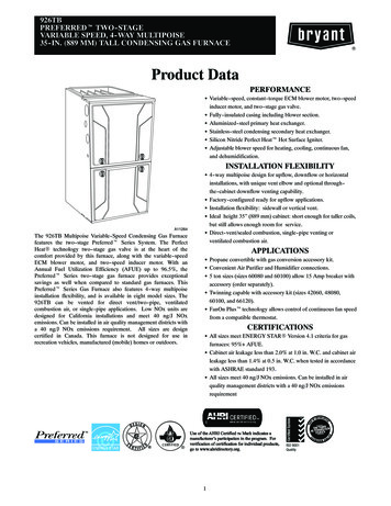
INSTALLATIONMOUNTING AND WIRINGAll wiring should be installed according to local and nationalelectrical codes and ordinances.The control must be secured to an area that will experience aminimum of vibration and remain below the maximum ambienttemperature rating of 175 F.The control is approved for minimumambient temperatures of -40 F.Any orientation is acceptable.Refer to the wiring diagram and wiring table when connectingthe 50V51 control to other components of the system.UL approved, 105 C rated 18 gauge min., stranded, 2/64” thickinsulation wire is recommended for all low voltage safety circuitconnections. Refer to 50V51 specification sheet for recommendedterminals to mate with those on the control.UL approved, 105 C rated 16 gauge min., stranded, 4/64” thickinsulation wire is recommended for all line voltage connections.Refer to 50V51 specification sheet for recommended terminalsto mate with those on the control.LENNOX NOTECERTAIN CONTROLS SUCH AS P/N 100870-01 HAVE ASPLIT IN THE OEM LIMIT CIRCUIT AND REQUIRE A MINORWIRING CHANGE OR THEY WILL PRODUCE A FLAMESENSE ERROR.The 50V51-843 has only one serviceable part –an automotivetype fuse, which protects the low voltage transformer from damage if the output is short-circuited. If the fuse has opened up,remove whatever caused the short circuit and replace the fusewith only a 3 Amp automotive type fuse. If the fuse does notcorrect the condition, replace the entire 50V51 control. Thereare not other user serviceable parts.Following installation or replacement, follow appliance manufacturer’s recommended installation or service instructions toinsure proper operation.INSTALLER MUST READ FOR PROPERINSTALLATION Wiring harnesses are included in this package to completethe installation of the “UNIVERSAL 50V51-843” for certainGoodman applications. Installer must read Option Switch Settings section and setswitches for proper control operation. For replacing the ignitor, a UNIVERSAL 21D64-2 is included.For proper installation, refer to the instructions included inthe 21D64-2 kit. IMPORTANT: The installer may have to enlarge existing ignitor hole to accommodate 21D64-2 larger (.394”) diameter.GOODMAN NOTECUT THE FACTORY WIRE CONNECTING TO 12-PIN MAINCONNECTOR PIN 3 (FLAME PROBE). SEE WIRING TABLEON PAGE 7.HARNESSES A & B ARE PIN TO SOCKET CONVERTERSAND ARE ONLY USED IF THE BOARD BEING REPLACEDHAS SOCKETS.ALL LIMITS WILL BE PROPERLY MONITORED THROUGHPIN 11. FLAME PROBE IS CONNECTED TO ¼” SPADE FP/ E34, UPPER LEFT OF PCB.THIS ALLOWS THE ORIGINAL FACTORY FURNACE WIRINGTO WORK WITH THE NEW 50V51-843 (21V51U-843 KIT)WHICH HAS PINS.OPTION SWITCH SETTINGSMOTOR OPTIMIZATIONAmana/Goodman/Trane/Lennox/Thermo Pride – The motorconfiguration DIP switches S3 and S4 must be set to matchIMPORTANT: Be sure to use proper switches for new boardsettings. Switch locations on old board may not be the samelocation as on the new board.SW3On the new board, the motor functions must be duplicated onDIP switched S3 and S4 per the following table.SW4ONONExisting 50V51OFF or 50V61OFF12345SW467York – The existing board has four shunt jumper banks to setmotor function configuration. The four jumper banks are designated DELAY (E45), COOL (E43), HEAT (E46), ADJ. (E44).Each jumper bank has four pair of pins to have jumper installedto determine the type of voltage to the motor. These pin pairsare A (no signal) B (positive Half-wave rectified), C (negativeHalf-wave rectified), D (Full-wave unrectified).8DELAYSW3Switch Position50V51-843OFF (New E46Jumper Banks(Existing BoardExample Settings)E443
OPTION SWITCH SETTINGSOn the new board, the motor functions must be duplicated onDIP switched S3 and S4 per the following table.Motor Configuration SettingsABCNo Signal Positive NegativeHalf Wave Half NSwitch Position50V51-843OFF (New BoardExample Settings)ONOFF12341234DIP Switch Selection for OEM Applications1OFF2OFFOFFONONONOFFONOEMTraneThermo Pride/GoodmanLennoxYorkDIP switches S7-1 and S7-2 (see table above) are set to the“Off” position from the factory for use with a multi-stage thermostat. This allows the thermostat to control staging betweenlow and high fire.Single Stage Thermostat Set-up,Module Controls StagingDIP switches, S7-1 and S7-2 (see table above) configure for asingle stage thermostat. Options include a 10 minute delay onsecond stage, 20 minute delay on second stage or an Auto setting allowing the module to calculate the time delay for secondstage based on average demand. The “Average CalculatedDuty Cycle” table shows how the module calculates stagingbased on demand.AverageCalculatedDuty Cycle% Equals03850627588or is lessthan3850627588100Low to HighStage DelayDemand12 minutesLight10 minutesLight to Average7 minutesAverage5 minutesAverage to Heavy3 minutesHeavy Light1 minuteHeavyHeat Fan Off Delay TimingFURNACE MANUFACTURERS2Multi-stage Thermostat Set-up,Factory DefaultOFF ON1DIP switches S7-3 and S7-4 (see table above) configure thenumber of seconds the blower will run after the call for heatends. Factory default is 90 seconds.HEAT PUMP AND DE-HUMIDIFICATION23S2IMPORTANT: Switch selection must match furnace manufacturer for proper motor operation.Set DIP switches S2-1 and S2-2 to match the equipment usingthe table above. NOTE: DIP switch S2-3 is not used.Heat PumpS5-1De-humidifierS5-2DIP SwitchesSwitchOptionsSettingsS5-1OffInstalledOnNot Installed*S5-2OffInstalledOnNot Installed*OFF ON12S5*Factory SettingsTHERMOSTAT TYPE AND HEAT-FAN-OFF-DELAYDIP SwitchesSwitch SettingsThermostatType and W2Delay S7-1,S7-2Heat Fan OffDelayS7-3, S7-4S7-1OffOnOffOnS7-3OffOffOnOn*Factory f*10 MinutesAuto20 MinutesTime90 Secs*120 Secs150 Secs180 SecsOFF ON1Heat Pump SystemsDIP switch S5-1 (see table above) is set to “On” from the factoryfor use with conventional (non-Heat Pump systems). For heatpump systems move the S5-1 DIP switch to the “Off” position.This will continuously output an O signal to the motor wheneverthere is Y signal and run the circulator blower at a constant speedwhen the pump is operating.2De-Humidification Connection3DIP switch S5-2 (see table above) is set to “On” from the factoryfor systems that do not have a dehumidification terminal connection from the thermostat. For systems using a thermostatthat provides a De-Humidification option move DIP switch S5-2to “Off”.4S7
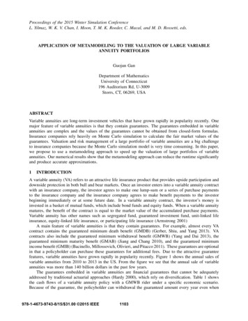
MOUNTING HOLE TEMPLATEMOUNTING HOLE TEMPLATEFOR MOUNTING HOLE LOCATIONS5
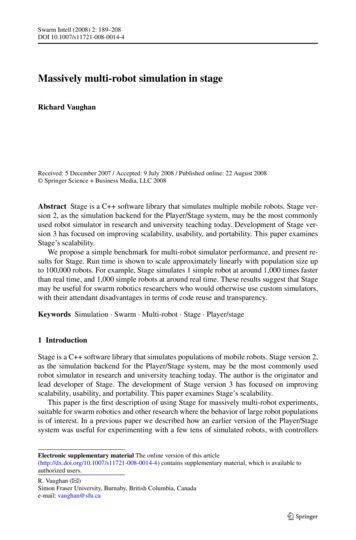
WIRINGHOT(LINE)50V51-843 TYPICAL SYSTEM WIRING DIAGRAMNEUTRAL(LINE)120 VAC24 VAC CLASS IITRANSFORMERTH24 VACTR50V51-843CIRC.CIRCULATOR INTERFACECIRCLINEXFMREACHUMIGNIND HIIND LOIND NIGN NINDUCERHUMIDIFIER(OPTIONAL)[5-Pin Connector]CIRC NHUM NLINE NXFMR NEAC NELECTRONICAIR NSORFP / E34PROBE*(2 OPTIONS)LEGENDB/COE2HIGH LIMIT ROLLOUT(N. C.) SWITCH (N. C.)HLOHLIFPPS1MVLMVHGNDGNDPS2MV COMTRTHAUX. HIGHLIMIT (N. C.)GASVALVE2ND STAGE PRESSURESWITCH (N. O.)[12-Pin Connector]GNDMVLGNDPS2THMVCOMHLOFPHLITRPS1MVHLow Voltage (24 VAC)Line Voltage (120 VAC)N.C. Normally closed switchN.O. Normally closed switch1ST STAGE PRESSURESWITCH (N. O.)IGNINDHIINDLOINDNIGNN5-Pin Connector12-Pin Connector*Flame sensor probe may connect either through 12-pin main connector or to 3/16" spadeconnector E34.6
WIRING50V51-843 TYPICAL SYSTEM WIRING UMOMVH (Pin 1)PS2 (Pin 2)FP (Pin 3)GND (Pin 4)TH (Pin 5)HLI (Pin 6)MVL (Pin 7)MV COM (Pin 8)TR (Pin 9)GND-2 terminals (Pin 10)HLO (Pin 11)PS1(Pin 12)IGN ( Pin 1)IND HI (Pin 2)IND LO (Pin 3)IND N (Pin 4)IGN N (Pin 12E2-13E2-14E2-15E2-16CIRCLINEXFMREAC (optional)HUM (optional)CIRC NLINE NXFMR NHUM N (optional)EAC N (optional)FP / E34two-stage thermostat W1 terminal (or equivalent)two-stage thermostat W2 terminal (or equivalent)two-stage thermostat G terminal (or equivalent)two-stage thermostat R terminal (or equivalent)two-stage thermostat B/C terminal (or equivalent)two-stage thermostat Y terminal (or equivalent)two-stage thermostat Y2 terminal (or equivalent)humidistat enable OUTPUT to circulatorH/P or cooling mode OUTPUT to OMHLOFPHLITRPS1IGNINDHIINDLOSYSTEM COMPONENTCONNECTIONINDNIGNNgas valve SECOND STAGE2nd stage pressure switch INPUTflame sensor probe*MUST BE RELIABLY GROUNDED TO CHASSIS24 VAC transformer (low voltage HIGH SIDE)high limit INPUTgas valve FIRST STAGEgas valve COMMON24 VAC transformer (low voltage COMMON SIDE)MUST BE RELIABLY GROUNDED TO CHASSIShigh limit OUTPUT1st stage pressure switch INPUTignitor HOT sideinducer HIGH SPEED HOT sideinducer LOW SPEED HOT sideinducer NEUTRAL sideignitor NEUTRAL side16-pinconnector& harness24 VAC COMMONlow heat speed select OUTPUT Circulator Blower24 VAC COMMONDelay tap OUTPUT to circulatorCool tap OUTPUT to circulator“YLO” OUTPUT to circulatoradjust tap OUTPUT to circulator24 VAC COMMON“O” OUTPUT to circulatorHumidistat/Y-Y2 OUTPUT to Circulator BlowerHeat tap OUTPUT to circulator24 VAC OUTPUT to circulator“W2” OUTPUT to circulator“Y” OUTPUT to circulator“G”/YLo OUTPUT to Circulator Blowergreen CFM indicatorspade terminalspade terminalspade terminalspade terminalspade terminalspade terminalspade terminalspade terminalspade terminalspade terminalspade terminalcirculator blower HOT terminalinput voltage (120 VAC) HOT side24 VAC transformer line voltage HOT sideelectronic air cleaner HOT sidehumidifier HOT sidecirculator blower NEUTRAL sideinput voltage (120 VAC) NEUTRAL side24 VAC transformer line voltage NEUTRAL sidehumidifier NEUTRAL sideelectronic air cleaner NEUTRAL sideflame sensor probe (Lennox)*NOTE: Spade terminals are 0.25” x 0.032”* maximum recommended flame probe wire length is 36 inches.7
OPERATIONNORMAL OPERATION – HEAT ONWhen the thermostat calls for heat the module verifies thepressure switches are open and energizes the inducer (highspeed) and optional humidifier contacts. When the low pressureswitch contacts close a 15 second pre-purge begins. After 15seconds the inducer switches to low speed and the 120 VACignitor is energized. The ignitor warms up for 17 seconds andthe gas valve is energized on low fire. Flame must be detectedwithin 4 seconds. If flame is detected, a 45 second heat,fan on time delay begins. This allows the heat exchanger towarm up before energizing the circulator on low speed and(optional) Electronic Air Cleaner contact. When the thermostat(or module) initiates second stage the inducer is energized athigh speed.This closes the second stage inducer pressure switch thenenergizes the second stage on the gas valve and then the highheat circulator speed.NORMAL OPERATION – HEAT OFFWhen the thermostat satisfies for second stage, the controlwill switch high speed inducer and high fire gas valve to lowspeed inducer and low fire gas valve. After the 30 second highheat fan delay the circulator will drop to low speed. When thethermostat satisfies for first stage the gas valve de-energizesand the inducer will run low speed for a 15 second post-purge.The circulator runs until the heat off delay ends.Note: If the module is configured for a single stage thermostatand running on second stage when the call for heat ends, thecirculator will drop to low speed after 30 seconds and continueuntil the heat off delay ends.COOL MODEIn a typical system, a call for cool is initiated by closing Yand G. This energizes the compressor and the electronic aircleaner (optional). The electronic air cleaner and the G and (Yor Ylo outputs to the Circulator motor will energize after the 5second cool on delay period. After the thermostat is satisfied,the compressor is de-energized and the control starts a 60second cool circulator speed off delay. After 60 seconds thecirculator is de-energized.MANUAL FAN ON MODEIf the thermostat fan switch is moved to the “ON” position, theelectronic air cleaner (optional) and the G circulator output tothe circulator motor will be energized. When the fan switch isreturned to the AUTO position, the G circulator output and theelectronic air cleaner are de-energized.TROUBLESHOOTINGSYSTEM LOCKOUTWhen a system lockout occurs (1hour), the gas valve is deenergized, the low speed inducer blower is energized for the60 second interpurge period and the circulator is energized forselected heat off delay if it was previously ON. The diagnosticindicator light will flash the fault that is present (refer todiagnostic table).To reset the control after system lockout, do one of thefollowing:System ResetRemove 24 VAC power to the control for twenty (20) secondsor longer to reset the control.Thermostat ResetRemove the call for heat from the thermostat for a period ofbetween (1) second and less 20 seconds. If flame is sensedwith the gas valve de-energized, interrupting the call for heatat the thermostat will not reset the control.Auto RestartAfter one (1) hour of internal or external lockout, the controlwill automatically reset itself and go into an auto restart purgefor 15 seconds.DIAGNOSTIC FEATURESThe control continuously monitors its own operation and theoperation of the system. If a failure occurs the diagnosticindicator LED (DSI) will flash a “RED” failure code. If a failureis internal to the control the “RED” indicator will stay on8continuously. In this case, the entire control should bereplaced as the control is not field-repairable. If the LEDis continuously OFF, there may be no power to the controlor a failure within the control. If the sensed failure is in thesystem (external to the control), the LED will flash RED inthe sequence listed in the Diagnostic Table. The LED will alsoindicate “System Status” as per the Amber and Green LEDsignatures listed in the Diagnostic Table. The LED will flash oneRED flash at power up.CFM INDICATORThe LED (DS2) CFM flashes when the blower motor is running.The flashing indicates the motor CFM (cubic feet per minute)air flow designated by the furnace manufacturer. Consult thefurnace manufacturer for flash code detail.FAULT CODE RETRIEVALTo retrieve fault codes, push and release the “LAST ERROR”button for more than 1/5 second and less than 5 seconds.(Control will indicate this period by solid GREEN for 1/5 secs.to 5 secs.). The LED will flash up to five stored fault codes,beginning with the most recent. If there are no fault codes inmemory, the LED will flash two green flashes. The control willflash the most recent error first and the oldest error last (last infirst out). There shall be 2 seconds between codes. Solid LEDerror codes will not be displayed.NOTEThese error codes may be different from furnace label orfurnace manual.
TRI-COLOR (DSI LED) DIAGNOSTIC TABLEGreenLEDFlashAmber Red LEDError/ConditionLEDFlashFlash1Flame sensed when no flame shouldbe present234567External lockout (retries exceeded)8External lockout (ignition recyclesexceeded where flame is establishedand then lost)Grounding or Reversed polarity9101112Solid1231Pressure switch stuck closed/ inducererror1st-stage pressure switch stuck open/inducer errorOpen limit switchOpen rollout/open fuse detect1st-stage pressure switch cyclelockoutModule gas valve contacts energizedwith no call for heatLimit switch open – possible blowerfailure overheating limitModule Ignitor contact failureModule - internal fault condition3 double 2nd-stage Pressure Switch StuckOpen/Inducer ErrorNormal Operation with call for firststage heatNormal Operation with call for secondstage heatW2 present with no W14Y present with no G callRapidLow flame sense currentStandby or Call for CoolComments/TroubleshootingVerify the gas valve is operating and shutting down properly. Flamein burner assemble should extinguish promptly at the end of thecycle. Check orifices and gas pressure.Pressure switch stuck closed. Check switch function, verify induceris turning off.Check pressure switch function and tubing. Verify inducer is turningon the pulling sufficient vacuum to engage switch.Verify continuity through rollout switch circuit.Verify continuity through rollout switch circuit, check fuse.If the first stage pressure switch cycles 5 times (open, closed)during one call for heat from the thermostat the control will lockout.Check pressure switch for fluttering, inconsistent closure or poorvacuum pressure.Failure to sense flame is often caused by carbon deposits on theflame sensor, a disconnected or shorted flame sensor lead or apoorly grounded furnace. Carbon deposits can be cleaned withemery cloth. Verify sensor is not contacting the burner and is locatedin a good position to sense flame. Check sensor lead for shortingand verify furnace is grounded properly.Check items for exceeded retries listed above and verify valve is notdropping out allowing flame to be established and then lost.Verify the control and furnace are properly grounded. Check andreverse polarity (primary) if incorrect.Verify valve is not receiving voltage from a short. If a valve wiring iscorrect and condition persists, replace module.Possible blower failure, restricted air flow through appliance orduct work. Verify continuity through limit switch circuit and correctoverheating cause.Fault code indicates the module ignitor contacts are not functioningproperly. Replace module.Module contacts for gas valve not operating or processor fault.Reset control. if condition persists replace module.Check pressure switch function and tubing. Verify inducer is turningon and pulling sufficient vacuum to engage switch.Normal operation - first stageNormal operation - first stageSecond stage call for heat on thermostat circuit with no call for firststage. Verify DIP switches are set for two stage thermostat andcheck thermostat first stage circuit. Configured for a multi-stagethermostat the Module will not initiate heating unless first stage callfrom thermostat is received.Module will allow cooling to operate with only a "Y signal fromthe thermostat but will also trigger this code. Verify thermostat isenergizing both "Y" and "G" on call for cool. Check "G" terminalconnections.Low flame sense current is often caused by carbon deposits onthe flame sensor, a poorly grounded furnace or a mis-alignedflame sense probe. Carbon deposits can be cleaned with emerycloth. Check for improve furnace and module ground. Verify sensoris located in or very near flame as specified by the appliancemanufacturer.Normal operation. Waiting for call from thermostat or receivingthermostat call for cool.9
NOTES
NOTES
TECHNICAL SUPPORT: 1-888-725-9797Emerson and White-Rodgers aretrademarks of Emerson Electric Co. 2020 Emerson Electric Co.All rights reserved.emerson.com/white-rodgers
and the activation of the blower motor at Heat speed. 45 Heat Delay-To-Fan-Off* The period of time between the loss of a call for heat and the deactivation of the blower motor at Heat speed. 90/120/150/180 Cool Delay-To-Fan-On The period of time after a thermostat demand for cool before energizing the circulator blower motor at Cool speed. 5