Transcription
MANUAL – TROUBLESHOOTINGECM MotorECM / ECM-DX Seriesv100 – Issue Date: 12/21/20 2020 Price Industries Limited. All rights reserved.
ECM MOTORTABLE OF CONTENTSECM Motor Background. 1ECM Motor Power and Control Connectors. 2ECM Motor Power Cable - 120 VAC. 2ECM Motor Power Cable - 240/277 VAC. 3NOTE: If a 120 VAC cable is used (with jumper) and 277VAC is applied to the motor it will be destroyedECM Motor Troubleshooting Checklist. 3ECM Speed Controller. 4Manual Mode. 4BAS Mode. 5Wiring and Cables. 9Typical Wiring Diagram. 14
ECM MotorTROUBLESHOOTINGECM Motor BackgroundECM MOTORThe ECM, or Electronically Commutated Motor, is a "smart"motor. Meaning it can be programmed to react to specificconditions.The ECM is electronically adjustable with an analog signal sentto the speed controller, or in some cases automatically adjustsitself to conditions. The ECM motor uses a quieter soft startwhen compared to standard AC motors and has much lowerpower consumption. The design is a combination of a veryefficient brushless DC motor, an integrated electronic controland extensive knowledge of the customer's application, whichis captured in the control's programming.Price is currently using the Genteq EON motor in 1/2 HP, 3/4HP and 1 HP sizes. Voltages for the motors are 120/240/277VAC single phase AC.While this motor is more complicated than a standard AC fanmotor there are many benefits. This manual will show you howto setup, program and troubleshoot ECM motors.There are two types of programs Price can load on to an ECM;Constant Volume, which is Price’s default, or Constant Torquefor special situations (contact application engineering).Constant Volume:This programming strategy has the motor speed up orslowdown in terms of RPM to compensate for changes insystem pressure in order to deliver a constant airflow. Forinstance, on a fan powered terminal equipped with a MERV13 filter, as the filter begins loading up with dust, the pressuredrop increases, and the ECM will speed itself up to maintain theairflow it is set for within 5%. As the primary air valve opens andless and less air is being pulled through the filter, and more air iscoming down the valve, the motor slows down to compensatefor less pressure drop to deliver the same airflow, within 5%.The ECM does this by measuring its own torque and RPM inreal time and uses the application specific program created inPrice’s lab to either speed up or slow down with any changesto either. Essentially as RPM begins to drop due to increasesin system pressure, torque increases to bring the RPM up, andvice versa. This transition happens seamlessly as the motor isrunning.allowed to vary. The ECM maintains all of its other benefits suchas low power consumption compared to regular AC motors,lower noise levels, and the ability to be electronically turnedup or down, it just won’t respond to pressure changes byincreasing or decreasing RPM to maintain airflow for any givenspeed setting. While this may not be ideal for the balancedfan terminal with filter mentioned above, it is advantageous forany situation where airflow is being varied by another device inseries with the ECM fan, and the ECM fan is being used simplyas a booster and is expected to react to the other device bydelivering the airflow that is provided to it. An example of thismight be an application where a cleanroom requires a variableCFM, so a single duct VAV and ECM Fan Filter Unit are usedin series. The VAV box will decide what CFM to output to theroom and the ECM fan in the Fan Filter Unit is only there tomake up the pressure drop of the filter. In this case it is notdesirable that the fan speed up as the air valve closes, theintent is for the fan to pass the air supplied to it over the filter.In fact if the ECM were programmed with a constant volumeprogram, the two pressure independent devices in series willusually oppose one another and cause instability where bothdevises constantly modulate between their upper and lowerlimits.Constant Torque:There are instances where a constant airflow program is notdesirable, and it would be preferential to have a motor thatreacts to changes in system pressure by riding the fan curve asa ‘dumb’ AC motor would. This is the constant torque program,where torque is held constant and RPM (and airflow) arepriceindustries.com ECM Motor - Troubleshooting Manual1
ECM MotorTROUBLESHOOTINGECM Motor Power and Control ConnectorsECM Motor Power Connector(120/240/277 VAC).ECM Motor Control Connector 16 Wiresfor programming 4 Wires for basiccontrol.NOTE: Connectors are keyed to resist thecables being inserted incorrectly.ECM Motor Power Cable - 120 VACBlack - Hot Wire (120V)White - Neutral WireGreen - Earth Ground WireJumper Wire - This sets motor to 120V2ECM Motor - Troubleshooting Manual priceindustries.com
ECM MotorTROUBLESHOOTINGECM Motor Power Cable - 240/277 VACBlack - Hot Wire (240/277 VAC)White - Neutral WireGreen - Earth Ground WireNOTE: NO Jumper Wire - 240/277 VAC.WARNING: If a 120 VAC cable is used(with jumper) and 277 VAC is applied tothe motor it will be destroyed.ECM Motor Troubleshooting ChecklistProblemMotor doesn't runMotor runs, but slowlyMotor Oscillates(revs fast then slow)Motor fails HIGH-POT testCheck 24 VAC transformer has power (test with AC volt meter) ECM speed controller has 24 VAC and green light is lit (See ECM Speed Controller Section) ECM speed controller POT/DIAL is adjusted properly (See ECM Speed Controller Section) ECM control cable is plugged in correctly and not damaged (See ECM Speed Controller Section) ECM Motor has proper power 120/240/277 VAC and cable is not damaged NOTE: If a motor has a 120VAC power cable (with a jumper) and 240/277 VAC is supplied to the motor it will be destroyed! Ensure ECM motor is programmed properly Check that blower wheel can be spun freely. Motor will go into a locked rotor fault if too muchresistance is sensed upon start up and motor will fail to start. Turn up (Clockwise) POT/DIAL on ECM speed controller (See ECM Speed Controller Section) ECM motor may have wrong program (example size 20 program, but motor is in a size 40 box) SeeECM Programming Section. Check ECM motor has proper power 120/240/277 VAC and cable is not damaged ECM motor may be BLANK (not programmed) – ensure motor has a label. If the motor is running slowlyand not responding to the speed controller, it’s very likely not programmed. ECM motor is trying to push too much air, ensure correct program in motor Turn down ECM speed controller POT/DIAL (See ECM Speed Controller Section) ECM is trying to push air against too high of an external static pressure ECM motor has small capacitors that are connected from Line 1 to ground. These capacitors are forfiltering out AC line noise; however they will cause a standard AC high test to fail. To properly test a DChigh POT tester must be used.priceindustries.com ECM Motor - Troubleshooting Manual3
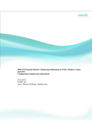
ECM MotorTROUBLESHOOTINGNOTE: If a motor has a 120 VAC power cable (with a jumper)and 240/277 VAC is supplied to the motor it will be destroyed!FIGURE 1 - ECM SPEED CONTROLLER (MANUAL SETTING)SAMPLE LABEL applied to factory programmed motorECM Standard Speed ControllerAll ECM Speed Controllers are manufactured by PriceElectronics in Winnipeg. It allows for ON/OFF and 0-100%speed control of any ECM motor (120/240/277 VAC, all HPs).ECM Speed Controllers have 2 modes. Manual adjust andBAS (BAS stands for Building Automation System).Manual ModeMeasure (-) VDCRange is 0-5 VDCOn a standard ECM speed controller, manual mode thespeed is controlled by adjusting the potentiometer (POT). ThePOT can adjusted from 0-100%. To set the POT preciselythe voltage output must be measured. Using a standardmultimeter on a DC voltage setting the ( ) and (-) tabs on theboard can be measured. The output is 0-5 VDC.4Measure ( ) VDCPOT VoltageMotor0 - 1 VDCOff1 - 4.5 VDC0-100% Control4.5 - 5 VDC100%ECM Motor - Troubleshooting Manual priceindustries.comFor each type of terminal unit and fan coil, there are equationsin the unit’s service and installation manual that will relate theairflow in CFM to the voltage measured across the taps on thefan speed controller. For example:A size 50 FDCA2 terminal unit with 277 volt ECM equation isas follows: CFM 672.29 (VDC) – 572.45So, in order to get 1400 CFM, we would need to rearrange theequation to get: (CFM 572.45) / 672.29 VDCThe POT would have to be turned up until the voltagemeasured at the taps is 2.94 VDC
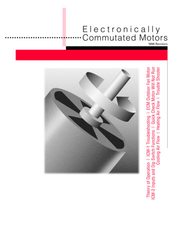
ECM MotorTROUBLESHOOTINGIn Building Automation Mode the speed controller reads a 2-10 VDC signal from a controller/computer to adjust the motor speed.NOTE: Speed Controller will automatically ignore the POT/DIAL when a BAS signal is detected!The 2-10 VDC signal is connected to the BAS Signal and BAS Common tabs. (NOTE: A 4-20 mA signal can be used as well.(series/current signal) However a jumper on the board must be relocated. Default is voltage input signal.)BAS Input SignalMotor0 - 1 VDCManual Mode(responds to POT/DIAL)1 - 2 VDCOff2 - 9 VDC0-100% Control9-10 VDC100%For BAS control, the same volts vs. CFM equations apply,but since the POT operates on a 1-5 volt scale, and theBAS operates on a 2-10 volt scale, the BAS scale is doublethe POT scale. Therefore whatever voltage is calculated fora specific CFM using the equations, the voltage must bedoubled in order to get that CFM by sending a BAS signal.For example:Size 50 FDCA2 with 277 volt ECM whose volts vs. CFM equation is:CFM 672.29 (VDC) – 572.45If the fan powered terminal requires a fan flow controlled by the BAS of 2000 CFM, rearranging the equation we get:(CFM 572.45) / 672.29 VDCThe VDC is for the POT however, so to get a CFM using the BAS input, the left side of the equation would need to be multiplied by2. Now we get:((CFM 572.45) / 672.29)) * 2 VDCTherefore, 2000 CFM would require a BAS voltage of 7.65 VDC.FIGURE 2 - ECM SPEED CONTROLLER FACEPotentiometer/Dial AdjustGreen Status LED must be blinking. (Code 1 thru 4)priceindustries.com ECM Motor - Troubleshooting Manual5
ECM MotorTROUBLESHOOTINGLED blink Sequence ChartStandard Speed Controller Hardware SpecificationsThe Diagnostic LED will blink out the current status used todetermine if the speed control is operating in manual/BASmode, and if current setting is OFF or CONTROL.Power24 VAC /- 10% @ 50/60 Hz (2 VA)OperatingConditions0 C to 50 C (32 F - 122 F) 0% - 95% R.H.NoncondensingModeVoltageStorageConditions-30 C - 50 C (-22 F - 122 F) 0% - 95%R.H. Noncondensing1Manual Mode(POT adjust) - OFF0 - 1 VDC(at POT taps)Processor8-bit flash microcontroller with on boardAnalog to Digital Converter2Manual Mode (POTadjust) - Control 0-100%1 - 5 VDC(at POT taps)Inputs2 Analog (1 manual adjust dial and 1 BAS0-10 VDC)3BAS Mode(1-2 VDC signal) - OFF1 - 2 VDC(at BAS taps)Outputs3 Digital (GO signal to ECM and Vspd PWMsignal @80.0 Hz) and LED4BAS Mode (2-10 VDCsignal) - Control 0-100%2 - 10 VDC(at BAS taps)Connections¼” Spade Terminals – Recommend 18-22AWG copper wireFault ModeDimensions53.3 mm by 43.2 mm (2.1” by 1.7”) Measure input voltage – ensure 24 VAC /- 10%Weight45.4 grams (0.1 lbs) Check wiring to speed control (ensure 24 VACHOT and Common are not reversed) Cycle 24 VAC power to unit Check BAS input wiring – NOTE: ‘BAS –‘ and24 VAC Common are connected – observepolarity when interfacing to other systemsBlinkLED OnSteadyof staysOFF*NOTE: BAS input of less than 1 volt means controller is inmanual (POT adjust) mode.FIGURE 3 - ECM STANDARD SPEED CONTROLLERBAS Common (NOTE: Same as 24 VAC Common)BAS Input Type Voltage or Current - Shown set to voltageControl Cable JacksBAS Positive Input (MAX 10 VDC)24 VAC HOT Power24 VAC Common (NOTE: Same as BAS Common)NOTE: BAS Common is connected to 24 VAC Common. If 24VAC is earth grounded then BAS Common will be earth groundas well. Polarity must be observed when connecting multiplespeed controllers and transformers.6ECM Motor - Troubleshooting Manual priceindustries.com
ECM MotorTROUBLESHOOTINGECM Deluxe Speed ControllerBAS Input SignalThe Price Deluxe ECM speed controller works with a highefficiency ECM motor. This low voltage (24 VAC) speed controlallows full manual (push button adjust) or BAS (2-10 VDCsignal) control of the ECM motor. The deluxe speed controlleralso has a digital screen and BAS RPM feedback (2-10 VDC)which is proportional to motor RPM.The BAS input signal overrides the local setpoint using aremote 0 – 10 VDC signal. If the BAS signal drops below 1VDC local control (via the push buttons) is restored.BASVoltageResponseNotesNOTE: 24 VAC COM, BAS COM, ANALOG OUTPUT COM areall connected together. Please observe 24 VAC polarity0-1VDCLocal control modeusing push buttonsLocal setpoint can beadjusted from 0 - 100%using push buttonsThe Digital Display shows the user several modes of operation.This allows for easier and more precise field adjustment andtroubleshooting. To change modes press both up and downbuttons at the same time.1-2VDCMotor OffRecommended sendinga 1.5 VDC signal tocommand motor off2-9VDCModulating Control2 - 9 VDC modulatesmotor from 0 - 100%9 - 10VDCMaximum SpeedMotor is running atmaximum speed (100%)NOTE: Local setpoints are stored to EEPROM and will remainset after power failures.WARNING: Do not switch 120/208/240/277 VAC power to turnECM motor on and off. Instead control the 24 VAC signal orBAS signal to turn the ECM motor on and off. The ECM motorhas large capacitors that charge quickly on mains power up.Switching on several motors frequently could reduce buildingpower qualityECM DELUXE SPEED CONTROLLERBAS equations exist in each fan powered terminal productservice and installation manual to relate CFM to volts DC.The VDC in the equations however are for the 1-5 volt scaleof voltage measured across the manual mode POT taps.The BAS input voltage is a 2-10 VDC scale, and thereforeVDC calculated for a given CFM using the equation mustbe doubled to achieve that CFM using the BAS input. Seestandard speed controller BAS section for an example ofcalculating the voltage required for a specific CFM.LCD DisplayDisplayL.SEtModeRangeLocal Setpoint – Manual speed adjustmode (use UP / DOWN to adjust)0 - 100%RPM – Shows current RPM of motor 1rPnIf E001 – no RPM pulses are beingread, check 6 position cable0 - 2500RPMIf E002 – RPM reading is above 2000RPM, check primary airbAS.rBAS Remote – BAS Mode – Voltagesignal (Max reading is 9.99 VDC)0 - 9.99VDCbAS.SBAS Setpoint – Current BAS setpoint0 - 100%priceindustries.com ECM Motor - Troubleshooting Manual7
ECM MotorTROUBLESHOOTINGAnalog RPM FeedbackA two wire connection supplies an analog (0-10 VDC) signalthat is directly proportional to the MOTOR 1 RPM. The rangeis 0 – 2500 RPM and it will output a proportional 0 – 10 VDCsignal. If a dual blower system is used, only the RPM of motor1 can be read.NOTE: The minimum speed of an ECM is approximately 250RPM. Formula for outputs below (tolerance /- 5%): VDC output (RPM /250) RPM (VDC * 250)Output signal: 0 – 10 VDC @ 20 k ohm minimum inputimpedance and is short circuit protected (output impedance is511 ohm to protect against incorrect wiring). Black Wire – Analog RPM output COM (-) White Wire – Analog RPM output signal ( )BACK OF ECMDXRPM VS. VOLTAGE2500220518901575126094563031508ECM Motor - Troubleshooting Manual priceindustries.comECM Deluxe Speed Controller Hardware SpecsPower24 VAC /- 10% 50/60 Hz (2VA)OperatingConditions0 C to 50 C (32 F to 122 F) 0% - 95% RHnon-condensingStorageConditions-30 C to 50 C (-22 F to 122 F) 0% - 95%RH non-condensingProcessor8-bit enhanced flash microcontrollerInputs1 Analog (BAS) and 3 digital inputs (Pushbuttons and RPM)Outputs2 Digital (GO signal to ECM, and Vspd PWMsignal @ 80Hz), Display, and aux analog outputConnections¼” Spade Terminals – Recommend 16 – 22AWG copper wireDimensions71 mm by 96 mm (2.8” by 3.8”) (includesmounting plate)ShippingWeight100 grams (0.220 lbs)
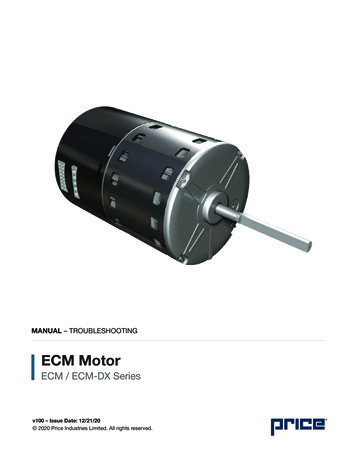
ECM MotorTROUBLESHOOTINGWiring and CablesThe ECM speed controller requires 24 VAC power from atransformer and outputs control signals to the ECM motor ondual MTA-100 jacks. Either jack or both jacks can be used (fordual fan systems).FIGURE 4 - ECM STANDARD SPEED CONTROLLER WITHCONTROL CABLE PLUGGED INTO MTR1The control cable (with RED connector) must be plugged intothe circuit board correctly (See Figure 4 and Figure 5).MTR1 JackECM Control Cable (NOTE: Orientation)NOTE: Connector OrientationFIGURE 5 - ECM STANDARD SPEED CONTROLLER WITHCONTROL CABLE PROPERLY CONNECTEDThe red connector is an AMP MTA connected. It is keyed toonly go in one way however it can (and has) been forced inbackwards.Ensure connector is inserted correctly.NOTE: if connector is inserted backwards the motor willrun erratically when the speed is adjusted with the speedcontroller.priceindustries.com ECM Motor - Troubleshooting Manual9
ECM MotorTROUBLESHOOTINGWiring and CablesThe ECM speed controller requires 24 VAC power from atransformer and outputs control signals to the ECM motor ondual MTA-100 jacks. Either jack or both jacks can be used (fordual fan systems).FIGURE 4 - ECM STANDARD SPEED CONTROLLER WITHCONTROL CABLE PLUGGED INTO MTR1The control cable (with RED connector) must be plugged intothe circuit board correctly (See Figure 4 and Figure 5).MTR1 JackECM Control Cable (NOTE: Orientation)NOTE: Connector OrientationFIGURE 5 - ECM STANDARD SPEED CONTROLLER WITHCONTROL CABLE PROPERLY CONNECTEDThe red connector is an AMP MTA connected. It is keyed toonly go in one way however it can (and has) been forced inbackwards.Ensure connector is inserted correctly.NOTE: if connector is inserted backwards the motor willrun erratically when the speed is adjusted with the speedcontroller.10ECM Motor - Troubleshooting Manual priceindustries.com
ECM MotorTROUBLESHOOTINGFIGURE 6 - ECM STANDARD SPEED CONTROLLER CONTROL CABLE PINOUTPin 1 – 9 - 30 VDC “GO” SIG (White)Pin 2 – Common (Black)Pin 3 – Common (Green)Pin 4 – 9 - 30 VDC “PWM” SIG (Red)MTR1MTR2NOTE: There are two motor output jacks (MTR1 & MTR2). Theyare in parallel so either one can be used. Both jacks are usedon dual blower units.MOTOR END OF CONTROL CABLEWhite (1)Black (2)Green (3)Red (4)SPEED CONTROLLER END OF CONTROL CABLELeft to right, 1, 2, 3, 4NOTE: If colors are different than shown here, ensure wires arestill going to correct position.priceindustries.com ECM Motor - Troubleshooting Manual11
ECM MotorTROUBLESHOOTINGFIGURE 6 - ECM STANDARD SPEED CONTROLLER CONTROL CABLE PINOUTPin 1 – UnusedPin 2 – UnusedPin 3 – Common (Blue)Pin 4 – 9 - 30 VDC “PWM” SIG (Yellow)MTR1MTR2NOTE: There are two motor output jacks (MTR1 & MTR2). Theyare in parallel so either one can be used. Both jacks are usedon dual blower units.SPEED CONTROLLER END OF CONTROL CABLENOTE: If colors are different than shown here, ensure wires arestill going to correct position.12ECM Motor - Troubleshooting Manual priceindustries.com
ECM MotorTROUBLESHOOTINGCONTROL CABLE - MOTOR CONNECTIONAccessible behind removable panel on external casing (fastened by 4 screws)CONTROL CABLE - MOTOR CONNECTIONMotor specification displayed on cover of external casingpriceindustries.com ECM Motor - Troubleshooting Manual13
ECM MotorTROUBLESHOOTINGTypical Wiring DiagramNOTE: The ECM motor is turned ON/OFF by switching 24 VAC power to the ECM speed controller. It is not recommended toswitch the main (120/240/277 VAC) power on and off. This is because the ECM motor has large capacitors that cause a currentsurge when turned on. This could cause a significant power spike if many units are turned on at once.14ECM Motor - Troubleshooting Manual priceindustries.com
This document contains the most current product information as of this printing.For the most up-to-date product information, please go to priceindustries.com 2020 Price Industries Limited. All rights reserved.
4 ECM Motor - troubleshooting Manual priceindustries.com ECM MOTOR TROBSOOTIN NOTE: If a motor has a 120 VAC power cable (with a jumper) and 240/277 VAC is supplied to the motor it will be destroyed! ECM Standard Speed Controller All ECM Speed Controllers are manufactured by Price Electronics in Winnipeg. It allows for ON/OFF and 0-100%