Transcription
CLIMATEMASTER SERIES 500PACKAGE AIRCONDITIONERRLRL-C SeriesWith Direct Digital ControlNominal Sizes 15 & 20 Tons [52.8 & 70.3 kW]ASHRAE 90.1-2007 CompliantRLRL-H SeriesWith Direct Digital Controland VFD TechnologyNominal Sizes 15 & 20 Tons [52.8 & 70.3 kW]ASHRAE 90.1-2010 CompliantManufactured forClimateMaster ClimateMaster.com
Table of ContentsRLRL-C/HTABLE OF CONTENTSUnit Features & Benefits .3-7Model Number Identification .8Options.9Selection Procedure .10General DataRLRL-C/H Series .11-13Gross Systems Performance DataRLRL-C/H Series .14-15Indoor Airflow PerformanceRLRL-C/H Series .16-18Electrical DataRLRL-C/H Series .19-20Electric Heater Kits .21-25Dimensional Data .26-32Accessories .33-46Mechanical Specifications .47-52Limited Warranty .532ClimateMaster
Unit Features & BenefitsRLRL-C/HRLRL-C/H STANDARD FEATURES INCLUDE: R-410A HFC refrigerant. Complete factory charged, wired and run tested. Scroll compressors with internal line break overload andhigh-pressure protection. Two-stage operation, two independent circuits. Convertible airflow – vertical downflow or horizontal sideflow. TXV refrigerant metering system on each circuit. High Pressure and Low Pressure/Loss of charge protectionstandard on all models. Solid Core liquid line filter drier on each circuit. Single slab, single pass designed evaporator and condensercoils facilitate easy cleaning for maintaining high efficiencies. Cooling operation up to 125 degree F ambient. Foil faced insulation encapsulated throughout entire unitminimizes airborne fibers from the air stream. Hinged major access door with heavy-duty gasketing, 1/4turn latches and door retainers. Slide Out Indoor fan assembly for added serviceconvenience. Powder Paint Finish meets ASTMB117 steel coated on eachside for maximum protection. G90 galvanized. Base pan with drawn supply and return opening for superiorwater management. Forkable base rails for easy handling and lifting. Single point electrical connections. Internally sloped slide out condensate pan conforms toASHRAE 62 standards. High performance belt drive motor with variable pitch pulleysand quick adjust belt system. Permanently lubricated evaporator, condenser and gas heatinducer motors. Condenser motors are internally protected, totally enclosedwith shaft down design. 2 inch filter standard with slide out design. 24 volt control system with resettable circuit breakers. Colored and labeled wiring. Copper tube/Aluminum Fin Evaporator coils. MicroChannel condenser coil. Supplemental electric heat provides 100% efficient heating. Factory Installed Direct Digital Control (DDC) and sensorswhich can connect to LonWorks or BACnet BAS systemsfor remote monitoring and control. -H models with supply fan Variable Frequency Drive (VFD)meets ASHRAE 90.1-2010 and California Title 24.ClimateMaster 3
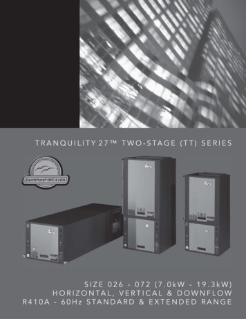
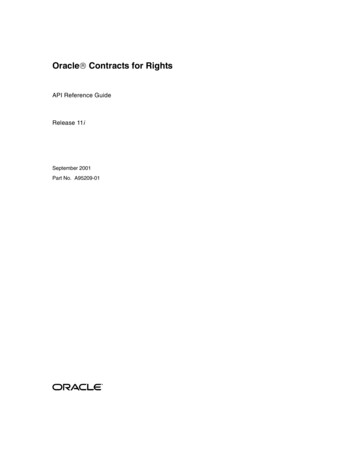
Unit Features & BenefitsRLRL-C/H231845ClimateMaster Package equipment is designed from the groundup with the latest features and benefits required to compete intoday’s market. The clean design stands alone in the industryand is a testament to the quality, reliability, ease of installationand serviceability that goes into each unit. Outwardly, the largeClimateMaster label ( 1 ) identifies the brand to the customer.The sheet-metal cabinet ( 2 ) uses nothing less than 20-gaugematerial for structural components with an underlying coat ofG90. To ensure the leak-proof integrity of these units, the designutilizes a top with a 1/8" drip lip ( 3 ), gasket-protected panelsand screws. ( 4 ) The outdoor coil is slanted to protect from hail.Every package unit uses the toughest finish in the industry, usingelectro deposition baked-on enamel tested to withstand a rigorous1000-hour salt spray test, per ASTM B117.Anything built to last must start with the right foundation. In thiscase, the foundation is 14-gauge, commercial-grade, fullperimeter base rails ( 5 ), which integrate fork slots and riggingholes to save set-up time on the job site. The base pan isstamped, which forms a 1-1/8" flange around the supply andreturn cover and has eliminated the worry of water entering theconditioned space ( 6 ). The drainpan ( 7 ) is made of materialthat resists the growth of harmful bacteria and is sloped for thelatest IAQ benefits. Furthermore, the drain pan slides out foreasy cleaning. The insulation has been placed on the undersideof the basepan, removing areas that would allow for potentialmoisture accumulation, which can facilitate growth of harmfulbacteria. All insulation is secured with both adhesive andmechanical fasteners, and all edges are hidden.66During development, each unit was tested to U.L. 1995, AHRI340-360 and other required reliability tests. ClimateMasteradheres to stringent IS0 9002 quality procedures, and eachunit bears the U.L. and AHRI certification labels located on theunit nameplate ( 8 ). Contractors can rest assured that when aClimateMaster package unit arrives at the job, it is ready to gowith a factory charge and quality checks.Access to all major compartments is from the front of the unit,including the filter and electrical compartment, blower compartment, heating section, and outdoor section. Each panel is permanently embossed with the compartment name (control/filteraccess, blower access and furnace access).Electrical and filter compartment access is through a large,hinged-access panel with 1/4 turn latches. On the outside of thepanel is the unit nameplate, which contains the model and serialnumber, electrical data and other important unit information.The unit charging chart is located on the inside of the electricaland filter compartment door. Electrical wiring diagrams arefound on the control box cover, which allows contractors tomove them to more readable locations. To the rightof the control box themodel and serial numbercan be found. Having thisinformation on the insidewill assure model identification for the life of theproduct. The production10line quality test assurancelabel is also placed in thislocation ( 9 ). The two9inch throwaway filters ( 10 )are easily removed on atracked system for easyreplacement.74ClimateMaster
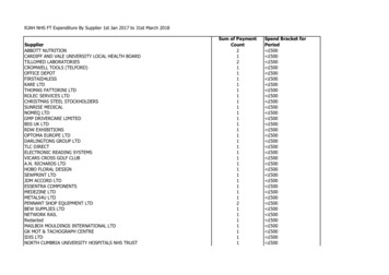
Unit Features & BenefitsRLRL-C/H10The RLRL-C/H is compatible with a third party building management system that supports the BACnet Application SpecificController device profile, with the use of a field installed BACnetCommunication Module. The BACnet Communication Moduleplugs onto the unit RTU-C controller and allows communicationbetween Direct Digital Control and the BACnet MSTP network.A zone sensor, a BACnet network zone sensor, a BACnet thermostat or DDC controller may be used to send the zone temperature or thermostat demands to the RTU-C. The BACnet Communication Module is compatible with MSTP EIA-485 daisy chainnetworks communicating at 38.4 bps. It is compatible with twistedpair, shielded cables.Inside the control box ( 11 ), eachelectrical component is clearlyidentified with a label that matchesthe component to the wire diagramfor ease of trouble shooting. Allwiring is numbered on each end ofthe termination and color-coded tomatch the wiring diagram. Thecontrol transformer has a low voltage circuit breaker that trips if alow voltage electrical short occurs.There is a blower contactor andcontactor for each compressor.11As part of the Direct Digital Controlsystem which allows real timemonitoring and communicationbetween rooftop units, theRLRL-C/H Package Air Conditionerhas a Rooftop Unit Controller(RTU-C) factory mounted12and wired in the controlpanel. The RTU-C is a solidstate microprocessor-basedcontrol board that providesflexible control and extensivediagnostics for all unit functions. The RTU-C throughproportional/integral controlalgorithms perform specificunit functions that governunit operation in response to: zone conditions, system temperatures, system pressures, ambient conditions and electricalinputs. The RTU-C features a 16 x 2 character LCD display and afive-button keypad for local configuration and direct diagnosis ofthe system ( 12 ). New features include a clogged filter switch(CFS), fan proving switch (FPS), return air temperature sensor(RAT), discharge air temperature sensor (DAT) and outdoor airtemperature sensor (OAT). Freeze sensors (FS) are used in placeof freezestats to allow measurement of refrigerant suction linetemperatures. The RLRL-C/H Package Air Conditioner with theDirect Digital Control is specifically designed to be applied infour distinct applications:The RLRL-C/H is compatible with a third party building management system that supports the LonMark Space Comfort Controller (SCC) functional profile or LonMark Discharge Air Controller (DAC) functional profile. This is accomplished with a fieldinstalled LonMark communication module. The LonMark Communication Module plugs onto the RTU-C controller and allowscommunication between Direct Digital Control and a LonWorksNetwork. A zone sensor, a LonTalk network zone sensor, or aLonTalk thermostat or DDC controller may be used to send thezone temperature or thermostat demands to the RTU-C. TheLonMark Communication Module utilizes an FTT-10A free topologytransceiver communicating at 78.8 kbps. It is compatible withEchelon qualified twisted pair cable, Belden 8471 or NEMALevel 4 cables. The Module can communicate up to 1640 ft.with no repeater. The LonWorks limit of 64 nodes per segmentapplies to this device.The RLRL-C/H is compatible with a programmable 24 volt thermostat. Connections are made via conventional thermostatscrew terminals. Extensive unit status and diagnostics are displayed on the LCD screen of the RTU-C.The RLRL-C/H is compatible with a zone sensor and mechanical or solid state time clock connected to the RTU-C. Extensiveunit status and diagnostics are displayed on the LCD screen ofthe Direct Digital Control.A factory or field installed Comfort Alert module is available forpower phase-monitoring protection and additional compressordiagnostics. The alarms can be displayed on the Direct DigitalControl display, through the (BAS) network, or connected to the“L-Terminal” of a thermostat for notification.ClimateMaster 5
Unit Features & BenefitsRLRL-C/H-H models with factory installed supply13fan VFD ( 13 ) (variable frequency drive)optimizes energy usage year round byproviding a lower speed for first stagecooling operation improving IEER’s byup to 33% over the conventional constant fan system. Furthermore, operating in the constant fan mode at thereduced speed can use as little as 1/8thof the energy of a conventional constantfan system. Also, by operating at alower speed on first stage cooling upto 126% more moisture is removedimproving comfort during low load operation. The VFD equipped units meetCalifornia Title 24 and ASHRAE 90.1-2010 requirements formulti blower speed control. VFD also ramps up to the desiredspeed reducing stress on the supply fan components andreducing the noise from sudden inrush of air. Because the airflow is cut in half during first stage cooling and constant fanoperation, noise is much less during these modes of operation.For added convenience in thefield, a factory-installed convenience outlet ( 14 ) is available.Low and High voltage can entereither from the side or through thebase. Low-voltage connectionsare made through the low-voltage14terminal strip. For ease of access,the U.L.-required low voltage barrier can be temporarilyremoved for low-voltage termination and then reinstalled. Thehigh-voltage connection is terminated at the high voltage terminal block. The suggested mounting for the field-installed disconnect is on the exterior side of the electrical control box.The blower compartment is to theright of the control box and can16be accessed by1/4 turn latches.To allow easymaintenance ofthe blowerassembly, theentire assemblyeasily slides out15by removing four#10 screws fromthe blower assembly. The adjustable motor pulley ( 15 ) can easilybe adjusted by loosening the bolts on either side of the motormount. Removing the bolts allows for easy removal of the blowerpulley by pushing the blower assembly up to loosen the belt.Once the pulley is removed, the motor sheave can be adjustedto the desired number of turns, ranging from 1 to 6 turns open.Where the demands for the job require high static, ClimateMasterhas high-static drives available that deliver nominal airflow up to2" of static. By referring to the airflow performance tables listedin the installation instructions, proper static pressure and CFMrequirements can be dialed in. The scroll housing ( 16 ) andblower scroll provide quiet and efficient airflow. The blowersheave is secured by an “H” bushing which firmly secures thepulley to the blower shaft for years of trouble-free operation. The“H” bushing allows for easy removal of the blower pulley from theshaft, as opposed to the use of a set screw, which can score theshaft, creating burrs that make blower-pulley removal difficult.6ClimateMaster Also inside the blower compartment are theoptional low-ambient controls ( 17 ). The optionallow-ambient controls allow for operation of thecompressors down to 0 degrees ambient temperature by cycling the outdoor fans on highpressure. The freeze sensor protects the compressor if the evaporator coil gets too cold(below freezing) due to low airflow, and allowsmonitoring of the suction line temperature on thecontroller display. The sensor clips on the suction line near the evaporator outlet.17Inside the blower compartment the interlaced evaporator can alsobe viewed. The evaporator uses enhanced fin technology for maximum heat transfer. The TXV metering device assures even distribution of refrigerant throughout the evaporator.Wiring throughout the unit is neatly bundled and routed. Wherewire harnesses go through the condenser bulkhead or blowerdeck, a molded wire harness assembly ( 18 ) provides an airtight and water-tight seal, and provides strain relief. Care is alsotaken to tuck raw edges of insulation behind sheet metal toimprove indoor air quality.The heating compartmentcontains the latest electric furnace technologyon the market. The 100%efficient electric furnacecan be factory-installedor easily field-installed.Built with ease-of-installation in mind, the electricfurnace is completelywired up for slide-in,plug-and-play installationin the field. With choices18of up to four kilowattofferings, the contractor is assured to get the correct amount ofheating output to meet the designed heating load.24251920232221Power hook-up in the field is easy with single-point wiring to aterminal block ( 19 ) and a polarized plug for the low-voltageconnection ( 20 ). The electric furnace comes with fuses for theunit ( 21 ) and for the electric furnace ( 22 ), and is UL certified( 23 ). The electric heating elements are of a wound-wire construction ( 24 ) and isolated with ceramic bushings. The limitswitch ( 25 ) protects the design from over-temperatureconditions.
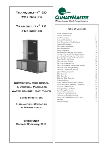
Unit Features & BenefitsRLRL-C/H3128302733293326The compressor compartment houses the heartbeat of the unit.The scroll compressor ( 26 ) is known for its long life, and for reliable, quiet, and efficient operation. The suction and dischargelines are designed with shock loops ( 27 ) to absorb the strainand stress that the starting torque, steady state operation, andshut down cycle impose on the refrigerant tubing. Each compressor and circuit is independent for built-in redundancy, andeach circuit is clearly marked throughout the system. Each unithas two stages of efficient cooling operation, first stage isapproximately 50% of second stage.In the outdoor section are the external gauge ports ( 28 ). Withthe gauge ports mounted externally, an accurate diagnosis ofsystem operation can be performed quickly and easily. Alsolocated in this area are the refrigerant safety devices: the lowpressure switches ( 29 ) and the high-pressure switches. ( 30 ) Thehigh-pressure switches will shut off the compressors if pressures exceeding 610 psig are detected as may occur if the outdoor fan motor fails. The low pressure switches shut off thecompressors if low pressure is detected due to loss of refrigerant charge. The factory-installed high and low pressureswitches are brazed into the appropriate high or low side andwired appropriately.Each unit comesstandard with filterdryer ( 31 ). The condenser fan motor( 32 ) can easily beaccessed and32maintained byremoving the protective fan grille. Thepolarized plug connection allows themotor to bechanged quicklyand eliminates the need to snake wires through the unit.The outdoor coil uses the latest enhanced fin design ( 33 ) forthe most effective method of heat transfer. The outdoor coil isslanted to protect the unit from Mother Nature.Each unit isdesigned forboth downflowor horizontal34applications34( 34 ) for jobconfigurationflexibility. Thereturn air compartmentcan also contain an economizer( 35 ). Three models exist; two fordownflow applications, and one for horizontalapplications. (A downflow economizer with factory installedsmoke detector in the return section is available). Each unit ispre-wired for the economizer to allow quick plug-in installation.The downflow economizer is also available as a factory-installedoption. The economizer, which provides free cooling when outdoor conditions are suitable and also provides fresh air to meetlocal requirements, comes standard with single enthalpy controls. The controls can be upgraded to dual enthalpy easily in thefield. The direct drive actuator combined with gear drivedampers has eliminated the need for linkage adjustment in thefield. The economizercontrol has a minimumposition setpoint, anoutdoor-air setpoint, amix-air setpoint, and aCO2 setpoint. Barometric 35relief is standard on alleconomizers. PowerExhaust is easily fieldinstalled. The powerexhaust is housed in thebarometric relief opening and is easily slipped in with a plug-inassembly. The wire harness to the economizer also has accommodations for a smoke detector.The damper minimum position, actual damper position, powerexhaust on/off setpoint, mixed air temperature limit setpoint andDemand Controlled Ventilation (DCV) setpoint can be read andadjusted at the unit controller display or remotely through anetwork connection.The Space CO2 level, mixed air temperature, and EconomizerStatus (Free Cooling Available, Single or Dual Enthalpy) can beread at the unit controller display or remotely through a networkconnection. Economizer Faults will trigger a network Alarm andcan be read at the unit controller display or remotely through anetwork connection.The roofcurb ( 36 ) is made for toolless assembly at thejobsite by inserting a pin into the hinged corners ( 37 ), whichmakes the assembly process quick36and easy.37ClimateMaster 7
Model Number IdentificationRLRL-C/HR L R L — C 180 C L 000 X X XEconomizer Option (See Next Page)Factory Installed Options(See Next Page)Electric Heat000 No Resistance Heat020 20 kW Resistance Heat040 40 kW Resistance Heat060 60 kW Resistance Heat075 75 kW Resistance HeatDrive PackageL Belt DriveM Belt Drive—High StaticN Belt Drive—Field InstalledR VFD Belt DriveS VFD Belt Drive High StaticT VFD Belt Drive High StaticField InstalledElectrical DesignationC 208-230 V, 3 PH, 60 HzD 460 V, 3 PH, 60 HzY 575 V, 3 PH, 60 HzCooling Capacity (BTUH) [kW]180 180,000 [52.75]240 240,000 [70.34]Future Technical VariationsC Direct Digital Control (DDC)H Direct Digital Control (DDC) with VFDDesign SeriesL R410A RefrigerantEfficiency DesignationR Ultra High EfficiencyASHRAE 90.1-2007 CompliantASHRAE 90.1-2010 Compliant (with VFD)Product ClassificationL Packaged Air Conditioner– CommercialTradebrandR ClimateMaster[8] Designates Metric ConversionsClimateMaster
OptionsRLRL-C/HFACTORY INSTALLED OPTION CODES FOR RLRL-C/H (15 & 20 TON) [52.8 & 70.3 kW]Option CodeNon-PoweredConvenience OutletHail GuardAAADAGARJDBJJECZLow Ambient/Comfort AlertNO OPTIONSxxxxxxxxxxxxExample: RLRL-C/H180CL000XXX (where XX is factory installed option)Example: No OptionsRLRL-C/H180CL000Example: No Options with factory installed economizerRLRL-C/H180CL000AAHExample: Options with low ambient/comfort alert and no factory installed economizerRLRL-C/H180CL000ARAExample: Options same as above with factory installed economizerRLRL-C/H180CL000ARHECONOMIZER SELECTION FOR RLRL-C/H (15 & 20 TON) [52.8 & 70.3 kW]OptionCodeAHJNo EconomizerDDC Single Enthalpy Economizer*With Barometric ReliefDDC Single Enthalpy Economizer*With Barometric Relief and Smoke Detectorxxx“x” indicates factory installed option.*Downflow economizer only.Instructions for Factory Installed Option(s) SelectionNote: Three characters following the model number will be utilized to designate a factory-installed option orcombination of options. If no factory option(s) is required, nothing follows the model number.Step 1. After a basic rooftop model is selected, choose a two-character option code from the FACTORYINSTALLED OPTION SELECTION TABLE.Proceed to Step 2.Step 2. The last option code character is utilized for factory-installed economizers. Choose a character fromthe FACTORY INSTALLED ECONOMIZER SELECTION TABLE.Examples:RLRL-C/H180CL000 .this unit has no factory installed options.RLRL-C/H180CL000ARA.this unit is equipped with low ambient/comfort alert.RLRL-C/H180CL000ARH.this unit is equipped with low ambient/comfort alert and economizer with single enthalpy sensor and barometric relief.RLRL-C/H180CL000AAJ .this unit is equipped with an Economizer with single enthalpy sensor and barometric relief with smoke detector.[] Designates Metric ConversionsClimateMaster 9
Selection ProcedureRLRL-C/HTo select an RLRL-C/H Cooling and Heating unit to meet a jobrequirement, follow this procedure, with example, using datasupplied in this specification sheet.5. CALCULATE INDOOR BLOWER BTUH HEAT EFFECTFROM MOTOR WATTS, STEP 4.1. DETERMINE COOLING AND HEATING REQUIREMENTSAND SPECIFIC OPERATING CONDITIONS FROM PLANSAND SPECS.6. CALCULATE NET COOLING CAPACITIES, EQUAL TOGROSS CAPACITY, STEP 3, MINUS INDOOR BLOWERMOTOR HEAT.Example:Voltage—240 V – 3 Phase – 60 HzTotal Cooling Capacity—205,000 BTUH [60.0 kW]Sensible Cooling Capacity—155,000 BTUH [45.4 kW]Heating Capacity—235,000 BTUH [68.8 kW]*Condenser Entering Air—95 F [35 C] DB*Evaporator Mixed Air Entering— 65 F [ 18.3] WB;78 F [ 25.6] DB*Indoor Air Flow (vertical)—7200 CFM [3398 L/s]*External Static Pressure—0.70 in. WG [.17 kPa]2,862 x 3.412 9,765 BTUH [2.86 kW]Net Total Capacity 235,868 – 9,765 226,103 BTUH [66.21 kW]Net Sensible Capacity 171,314 – 9,765 161,549 BTUH [47.30 kW]7. CALCULATE UNIT INPUT AND JOB EER.Total Power Input 18,018 (step 3) 2,862(step 4) 20,880 WattsEER 2. SELECT UNIT TO MEET COOLING REQUIREMENTS.Since total cooling is within the range of a nominal 20 ton [70.3kW] unit, enter cooling performance table at 95 F [35.0 C] DBcondenser inlet air. Interpolate between 63 F [17.2 C] WB and67 F [19.4 C] WB to determine total and sensible capacityand power input for 65 F [18.3 C] WB evaporator inlet air at7725 CFM [3645 L/s] indoor air flow (table basis):8. SELECT UNIT HEATING CAPACITY.From Heater Kit Table select kW to meet heating capacityrequirement; multiply kW x 3412 to convert to BTUHUse 75 kW Heater KitHeater Kit Model: RXJJ-CE75CHeater Kit Capacity: 245,323 BTUH [71.8 kW]Total Cooling Capacity 238,300 BTUH [69.76 kW]Sensible Cooling Capacity 192,500 BTUH [56.38 kW]Power Input (Compressor and Cond. Fans) 18,200 wattsAdd indoor blower heat effect (step 5) to Heater Kit Capacityto get total heating capacity:Use formula in note ➀ to determine sensible capacity at 78 F[25.6] DB evaporator entering air:192,550 (1.10 x 7,200 x (1 – 0.11) x (78 – 80))Net Total BTUH [kW] (step 6) 226,103 10.83Power Input, Watts (above)20,880245,323 9,765 255,088 BTUH [74.7 kW]9. CHOOSE MODEL RLRL-C/H240CL075Sensible Cooling Capacity 178,452 BTUH [52.25 kW]3. CORRECT CAPACITIES OF STEP 2 FORACTUAL AIR FLOW.Select factors from airflow correction table at 7200 CFM[3398 L/s] and apply to data obtained in step 2 to obtaingross capacity:Total Capacity 238,300 x .99 235,868 BTUH [69.06 kW]Sensible Capacity 178,452 x 0.96 171,314 BTUH [50.16 kW]Power Input 18,200 x 0.99 18,018 WattsThese are Gross Capacities, not corrected for blower motorheat or power.4. DETERMINE BLOWER SPEED AND WATTS TO MEETSYSTEM DESIGN.Enter Indoor Blower performance table at 7200 CFM [3398L/s]. Total ESP (external static pressure) per the spec of 0.70in. WG [.17 kPa] includes the system duct and grilles. Addfrom the table 'Component Air Resistance', 0.01 in. WG[.00 kPa] for wet coil, 0.08 in. WG [.02 kPa] for downflow airflow, for a total selection static pressure of 0.79 (0.8) in. WG[.20 kPa], and determine:RPM 739WATTS 2,862DRIVE L (standard 5 H.P. motor)10ClimateMaster *NOTE: These operating conditions are typical of a commercial application in a 95 F/79 F [35 C/26 C] design area with indoor designof 76 F [24 C] DB and 50% RH and 10% ventilation air, withthe unit roof mounted and centered on the zone it conditionsby ducts.[] Designates Metric Conversions
General DataRLRL-C/HNOM. SIZES 15 & 20 TONS [52.8 & 70.3 kW] MODELSModel RLRL- SeriesModel RLRL- Series (with VFD)Cooling Performance1Gross Cooling Capacity Btu 180DMH180DSCONTINUEDContinued- 178,000 [50.63]178,000 [50.63]178,000 [50.63]178,000 [50.63]11.6/NA11.6/NA11.6/NA11.6/NANominal CFM/AHRI Rated CFM [L/s]6000/5500 [2831/2595]6000/5500 [2831/2595]6000/5500 [2831/2595]6000/5500 [2831/2595]AHRI Net Cooling Capacity Btu [kW]172,000 [48.92]172,000 [48.92]172,000 [48.92]172,000 [48.92]Net Sensible Capacity Btu [kW]126,000 [35.84]126,000 [35.84]126,000 [35.84]126,000 [35.84]Net Latent Capacity Btu [kW]46,000 [13.08]46,000 [13.08]46,000 [13.08]46,000 [13.08]IEER3 (Standard / VFD)12.4/14.212.4/14.212.4/14.212.4/14.2Net System Power oChannelMicroChannelMicroChannelMicroChannel1 [25.4]1 [25.4]1 [25.4]1 [25.4]50.8 [4.72]50.8 [4.72]50.8 [4.72]50.8 [4.72]CompressorNo./TypeOutdoor Sound Rating (dB)4Outdoor Coil—Fin TypeTube TypeTube Size in. [mm] ODFace Area sq. ft. [sq. m]Rows / FPI [FPcm]1 / 23 [9]1 / 23 [9]1 / 23 [9]1 / 23 [9]Indoor Coil—Fin TypeTube fledRifledTube Size in. [mm]0.375 [9.5]0.375 [9.5]0.375 [9.5]0.375 [9.5]Face Area sq. ft. [sq. m]26.67 [2.48]26.67 [2.48]26.67 [2.48]26.67 [2.48]Rows / FPI [FPcm]Refrigerant Control2 / 18 [7]2 / 18 [7]2 / 18 [7]2 / 18 [7]TX ValvesTX ValvesTX ValvesTX ValvesDrain Connection No./Size in. [mm]1/1 [25.4]1/1 [25.4]1/1 [25.4]1/1 [25.4]PropellerPropellerPropellerPropeller3/24 [609.6]3/24 [609.6]3/24 [609.6]3/24 [609.6]Outdoor Fan—TypeNo. Used/Diameter in. [mm]Drive Type/No. SpeedsCFM [L/s]No. Motors/HPMotor RPMIndoor Fan—TypeNo. Used/Diameter in. [mm]Direct/1Direct/1Direct/1Direct/110000 [4719]10000 [4719]10000 [4719]10000 [4719]3 at 1/3 HP3 at 1/3 HP3 at 1/3 HP3 at 1/3 HP1075107510751075FC CentrifugalFC CentrifugalFC CentrifugalFC Centrifugal2/18x9 [457x229]2/18x9 [457x229]2/18x9 [457x229]2/18x9 [457x229]Drive TypeBelt (Adjustable)Belt (Adjustable)Belt (Adjustable)Belt (Adjustable)No. Speeds (Standard / VFD)Single / MultipleSingle / MultipleSingle / MultipleSingle / MultipleNo. Motors1111Motor HPMotor RPM35351725172517251725Motor Frame SizeFilter—TypeFurnished(NO.) Size Recommended in. [mm x mm x mm]Refrigerant Charge Oz. [g] (Sys. 1/Sys. 2) bleYesYesYesYes(8)2x25x20 [51x635x508](8)2x25x20 [51x635x508](8)2x25x20 [51x635x508](8)2x25x20 [51x635x508]170/173 [4820/4905]170/173 [4820/4905]170/173 [4820/4905]170/173 [4820/4905]1883 [854]1921 [871]1883 [854]1921 [871]2009 [911]2047 [929]2009 [911]2047 [929]WeightsNet Weight lbs. [kg]Ship Weight lbs. [kg]NOTES:1. Cooling Performance is rated at 95 F ambient, 80 F entering dry bulb, 67 F entering wet bulb. Gross capacity doesnot include the effect of fan motor heat. AHRI capacity is net and includes the effect of fan motor heat. Units aresuitable for operation to 20% of nominal cfm. Units are certified in accordance with the Unitary Air ConditionerEquipment certification program, which is based on AHRI Standard 210/240 or 360.2. EER and/or SEER are rated at AHRI conditions and in accordance with DOE test procedures.3. Integrated Energy Efficiency Ratio (IEER) is rated in accordance with AHRI Standard 210/240 or 340/360.4. Outdoor Sound Rating shown is tested in accordance with AHRI Standard 270.5. 25 Ton Model is outside the scope of AHRI Standard 340/360.[] Designates Metric ConversionsClimateMaster 11
General DataRLRL-C/HNOM. SIZES 15 & 20 TONS [52.8 & 70.3
CLIMATEMASTER SERIES 500 PACKAGE AIR CONDITIONER RLRL-C Series With Direct Digital Control Nominal Sizes 15 & 20 Tons [52.8 & 70.3 kW] ASHRAE 90.1-2007 Compliant RLRL-H Series With Direct Digital Control and VFD Technology Nominal Sizes 15 & 20 Tons [52.8 & 70.3 kW] ASHRAE 90.1-2010 Compliant Manufactured for ClimateMaster ClimateMaster.com